Experimental observation of localized
structures in medium size VCSELs
Etienne Averlant,1,2,∗Mustapha Tlidi,1Hugo Thienpont,2 Thorsten Ackemann,3and Krassimir Panajotov2,4
1Facult´e des Sciences, Universit´e Libre de Bruxelles (ULB), Code Postal 231, Campus Plaine,
Bruxelles B-1050, Belgium,
2Department of Applied Physics and Photonics (IR-TONA), Vrije Universiteit Brussel,
Pleinlaan 2, Brussels B-1050, Belgium,
3SUPA and Department of Physics, University of Strathclyde, Glasgow G4 0NG, Scotland,
UK
4Institute of Solid State Physics, 72 Tzarigradsko Chaussee Boulevard, Sofia 1784, Bulgaria ∗[email protected]
Abstract: We report experimental evidence of spontaneous formation of localized structures in a 80μm diameter Vertical-Cavity Surface-Emitting Laser (VCSEL) biased above the lasing threshold and under optical injec-tion. Such localized structures are bistable with the injected beam power and the VCSEL current. We experimentally investigate the formation of localized structures for different detunings between the injected beam and the VCSEL, and different injection beam waists.
© 2014 Optical Society of America
OCIS codes: (190.1450) Bistability; (190.4420) Nonlinear optics, transverse effects in;
(190.5970) Semiconductor nonlinear optics including MQW; (190.6135) Spatial solitons.
References and links
1. M. Tlidi, M. Taki, and T. Kolokolnikov, “Introduction: dissipative localized structures in extended systems,” Chaos17, 037101 (2007).
2. N. Akhmediev and A. Ankiewicz,Dissipative Solitons: From Optics to Biology and Medicine(Springer, 2008), Vol. 751.
3. T. Ackemann, W. J. Firth, and G. Oppo, “Fundamentals and applications of spatial dissipative solitons in photonic devices,” inAdvances in Atomic Molecular and Optical Physics, Vol. 57 ofAdvances in Atomic, Molecular, and Optical Physics, P. R. B. E. Arimondo and C. C. Lin, eds. (Academic, 2009), Chap. 6, p. 323–421.
4. R. Kuszelewicz, S. Barbay, G. Tissoni, and G. Almuneau, “Editorial on dissipative optical solitons,” Eur. Phys. J. D59, 1 (2010).
5. O. Descalzi, M. Clerc, and S. Residori,Localized States in Physics: Solitons and Patterns(Springer, 2011). 6. H. Leblond and D. Mihalache, “Models of few optical cycle solitons beyond the slowly varying envelope
ap-proximation,” Phys. Rep.523, 61–126 (2013).
7. H. G. Purwins, H. U. B¨odeker, and S. Amiranashvili, “Dissipative solitons,” Adv. Phys.59, 485–701 (2010).
8. V. K. Vanag, L. Yang, M. Dolnik, A. M. Zhabotinsky, and I. R. Epstein, “Oscillatory cluster patterns in a homo-geneous chemical system with global feedback,” Nature406, 389–391 (2000).
9. K.-J. Lee, W. D. McCormick, J. E. Pearson, and H. L. Swinney, “Experimental observation of self-replicating spots in a reaction-diffusion system,” Nature369, 215–218 (1994).
10. I. Lengyel and I. R. Epstein, “A chemical approach to designing turing patterns in reaction-diffusion systems,” Proc. Natl. Acad. Sci. U. S. A.89, 3977–3979 (1992).
11. V. K. Vanag and I. R. Epstein, “Stationary and oscillatory localized patterns, and subcritical bifurcations,” Phys. Rev. Lett.92, 128301 (2004).
12. T. Kolokolnikov and M. Tlidi, “Spot deformation and replication in the two-dimensional belousov-zhabotinski reaction in a water-in-oil microemulsion,” Phys. Rev. Lett.98, 188303 (2007).
14. O. Lejeune, M. Tlidi, and P. Couteron, “Localized vegetation patches: A self-organized response to resource scarcity,” Phys. Rev. E66, 010901 (2002).
15. M. Rietkerk, S. C. Dekker, P. C. de Ruiter, and J. van de Koppel, “Self-organized patchiness and catastrophic shifts in ecosystems,” Science305, 1926–1929 (2004).
16. E. Meron, H. Yizhaq, and E. Gilad, “Localized structures in dryland vegetation: Forms and functions,” Chaos17,
037109 (2007).
17. M. Tlidi, R. Lefever, and A. Vladimirov, “On vegetation clustering, localized bare soil spots and fairy circles,” inDissipative Solitons: From Optics to Biology and Medicine, Vol. 751 ofLecture Notes in Physics(Springer, 2008), pp. 381–402.
18. Y. Pomeau, “Front motion, metastability and subcritical bifurcations in hydrodynamics,” Physica D,23, 3–11
(1986).
19. A.R. Champneys, “Homoclinic orbits in reversible systems and their applications in mechanics, fluid and op-tics,” Physica D,112, 158–186 (1998).
20. P. Coullet, C. Riera, and C. Tresser, “Stable static localized structures in one dimension,” Phys. Rev. Lett.84,
3069–3072 (2000)
21. D. W. McLaughlin, J. V. Moloney, and A. C. Newell, “Solitary waves as f xed points of infinite-dimensiona maps in an optical bistable ring cavity,” Phys. Rev. Lett.51, 75–78 (1983).
22. N. N. Rosanov and G. V. Khodova, “Diffractive autosolitons in nonlinear interferometers,” J. Opt. Soc. Am. B7,
1057–1065 (1990).
23. M. Tlidi, P. Mandel, and R. Lefever, “Localized structures and localized patterns in optical bistability,” Phys. Rev. Lett.73, 640–643 (1994).
24. A. J. Scroggie, W. J. Firth, G. S. McDonald, M. Tlidi, R. Lefever, and L. A. Lugiato, “Pattern formation in a passive kerr cavity,” Chaos Solitons Fract.4, 1323–1354 (1994).
25. A. G. Vladimirov, R. Lefever, and M. Tlidi, “Relative stability of multipeak localized patterns of cavity solitons,” Phys. Rev. A84, 043848 (2011).
26. M. Saffman, D. Montgomery, and D. Z. Anderson, “Collapse of a transverse-mode continuum in a self-imaging photorefractively pumped ring resonator,” Opt. Lett.19, 518–520 (1994).
27. N. Verschueren, U. Bortolozzo, M. G. Clerc, and S. Residori, “Spatiotemporal chaotic localized state in liquid crystal light valve experiments with optical feedback,” Phys. Rev. Lett.110, 104101 (2013).
28. U. Bortolozzo and S. Residori, “Storage of localized structure matrices in nematic liquid crystals,” Phys. Rev. Lett.96, 037801 (2006).
29. A. Schreiber, B. Th¨uring, M. Kreuzer, and T. Tschudi, “Experimental investigation of solitary structures in a nonlinear optical feedback system,” Opt. Commun.136, 415–418 (1997).
30. V. B. Taranenko, K. Staliunas, and C. O. Weiss, “Spatial soliton laser: Localized structures in a laser with a saturable absorber in a self-imaging resonator,” Phys. Rev. A56, 1582–1591 (1997).
31. V. B. Taranenko, K. Staliunas, and C. O. Weiss, “Pattern formation and localized structures in degenerate optical parametric mixing,” Phys. Rev. Lett.81, 2236–2239 (1998).
32. K. Staliunas, V. B. Taranenko, G. Slekys, R. Viselga, and C. O. Weiss, “Moving spatial solitons in active nonlinear-optical resonators,” Phys. Rev. A57, 599–604 (1998).
33. Y. A. Logvin, B. Sch¨apers, and T. Ackemann, “Stationary and drifting localized structures near a multiple bifur-cation point,” Phys. Rev. E61, 4622–4625 (2000).
34. B. Sch¨apers, M. Feldmann, T. Ackemann, and W. Lange, “Interaction of localized structures in an optical pattern-forming system,” Phys. Rev. Lett.85, 748–751 (2000).
35. V. Odent, M. Taki, and E. Louvergneaux, “Experimental evidence of dissipative spatial solitons in an optical passive kerr cavity,” New J. Phys.13, 113026 (2011).
36. S. V. Fedorov, A. G. Vladimirov, G. V. Khodova, and N. N. Rosanov, “Effect of frequency detunings and finit relaxation rates on laser localized structures,” Phys. Rev. E61, 5814–5824 (2000).
37. L. Gelens, G. Van der Sande, P. Tassin, M. Tlidi, P. Kockaert, D. Gomila, I. Veretennicoff, and J. Danckaert, “Impact of nonlocal interactions in dissipative systems: Towards minimal-sized localized structures,” Phys. Rev. A75, 063812 (2007).
38. M. Brambilla, L. A. Lugiato, F. Prati, L. Spinelli, and W. J. Firth, “Spatial soliton pixels in semiconductor devices,” Phys. Rev. Lett.79, 2042–2045 (1997).
39. L. Spinelli, G. Tissoni, M. Brambilla, F. Prati, and L. A. Lugiato, “Spatial solitons in semiconductor microcavi-ties,” Phys. Rev. A58, 2542–2559 (1998).
40. V. B. Taranenko, I. Ganne, R. J. Kuszelewicz, and C. O. Weiss, “Patterns and localized structures in bistable semiconductor resonators,” Phys. Rev. A61, 063818 (2000).
41. S. Barland, J. R. Tredicce, M. Brambilla, L. A. Lugiato, S. Balle, M. Giudici, T. Maggipinto, L. Spinelli, G. Tis-soni, T. Kn¨odl, “Cavity solitons as pixels in semiconductor microcavities,” Nature419, 699–702 (2002).
42. Y. Menesguen, S. Barbay, X. Hachair, L. Leroy, I. Sagnes, and R. Kuszelewicz, “Optical self-organization and cavity solitons in optically pumped semiconductor microresonators,” Phys. Rev. A74, 023818 (2006).
43. Y. Larionova and C. O. Weiss, “Spatial semiconductor resonator solitons with optical pumping,” Opt. Express
13, 10711–10716 (2005).
L. A. Lugiato, I. Protsenko, and M. Brambilla, “Cavity solitons in a driven vcsel above threshold,” IEEE J. Sel. Top. Quantum Electron.12, 339–351 (2006).
45. S. Barbay, R. Kuszelewicz, and J. R. Tredicce, “Cavity solitons in vcsel devices,” Adv. Opt. Technol.2011,
628761 (2011).
46. F. Pedaci, S. Barland, E. Caboche, P. Genevet, M. Giudici, J. R. Tredicce, T. Ackemann, A. J. Scroggie, W. J. Firth, G. L. Oppo, G. Tissoni, and R. J¨ager, “All-optical delay line using semiconductor cavity solitons,” Appl. Phys. Lett.92, 011101 (2008).
47. A. Jacobo, D. Gomila, M. A. Mat´ıas, and P. Colet, “Logical operations with localized structures,” New J. Phys.
14, 013040 (2012).
48. F. Pedaci, G. Tissoni, S. Barland, M. Giudici, and J. Tredicce, “Mapping local defects of extended media using localized structures,” Appl. Phys. Lett.93, 111104 (2008).
49. T. Elsass, K. Gauthron, G. Beaudoin, I. Sagnes R. Kuszelewicz, S. Barbay, “Fast manipulation of laser localized structures in a monolithic vertical cavity with saturable absorber,” Appl. Phys. B98, 327–331 (2010).
50. P. Genevet, S. Barland, M. Giudici, and J. R. Tredicce, “Cavity soliton laser based on mutually coupled semicon-ductor microresonators,” Phys. Rev. Lett.101, 123905 (2008).
51. Y. Tanguy, T. Ackemann, W. J. Firth, and R. J¨ager, “Realization of a semiconductor-based cavity soliton laser,” Phys. Rev. Lett.100, 013907 (2008).
52. N. Radwell and T. Ackemann, “Characteristics of laser cavity solitons in a vertical-cavity surface-emitting laser with feedback from a volume bragg grating,” IEEE J. Quantum Electron.45, 1388–1395 (2009).
53. L. Spinelli, G. Tissoni, L. A. Lugiato, and M. Brambilla, “Thermal effects and transverse structures in semicon-ductor microcavities with population inversion,” Phys. Rev. A66, 023817 (2002).
54. A. J. Scroggie, J. M. McSloy, and W. J. Firth, “Self-propelled cavity solitons in semiconductor microcavities,” Phys. Rev. E66, 036607 (2002).
55. M. Tlidi, A. G. Vladimirov, D. Pieroux, and D. Turaev, “Spontaneous motion of cavity solitons induced by a delayed feedback,” Phys. Rev. Lett.103, 103904 (2009).
56. M. Tlidi, E. Averlant, A. Vladimirov, and K. Panajotov, “Delay feedback induces a spontaneous motion of two-dimensional cavity solitons in driven semiconductor microcavities,” Phys. Rev. A86, 033822 (2012).
57. E. Averlant, M. Tlidi, A. G. Vladimirov, H. Thienpont, and K. Panajotov, “Delay induces motion of multipeak localized structures in cavity semiconductors,” Proc. SPIE8432, 84321D (2012).
58. S. V. Gurevich and R. Friedrich, “Instabilities of localized structures in dissipative systems with delayed feed-back,” Phys. Rev. Lett.110, 014101 (2013).
59. K. Panajotov and M. Tlidi, “Spontaneous motion of cavity solitons in vertical-cavity lasers subject to optical injection and to delayed feedback,” Eur. Phys. J. D59, 67–72 (2010).
60. F. Prati, G. Tissoni, L. A. Lugiato, K. M. Aghdami, and M. Brambilla, “Spontaneously moving solitons in a cavity soliton laser with circular section,” Eur. Phys. J. D59, 73–79 (2010).
61. X. Hachair, S. Barland, L. Furfaro, M. Giudici, S. Balle, J. R. Tredicce, M. Brambilla, T. Maggipinto, I. M. Perrini, G. Tissoni, and L. Lugiato, “Cavity solitons in broad-area vertical-cavity surface-emitting lasers below threshold,” Phys. Rev. A69, 043817 (2004).
62. X. Hachair, L. Furfaro, J. Javaloyes, M. Giudici, S. Balle, J. Tredicce, G. Tissoni, L. A. Lugiato, M. Brambilla, and T. Maggipinto, “Cavity-solitons switching in semiconductor microcavities,” Phys. Rev. A72, 013815 (2005).
63. X. Hachair, G. Tissoni, H. Thienpont, and K. Panajotov, “Linearly polarized bistable localized structure in medium-size vertical-cavity surface-emitting lasers,” Phys. Rev. A79, 011801 (2009).
64. M. Grabherr, M. Miller, R. Jager, R. Michalzik, U. Martin, H. J. Unold, and K. J. Ebeling, “High-power vcsels: single devices and densely packed 2-d-arrays,” IEEE J. Sel. Top. Quantum Electron.5, 495–502 (1999).
65. M. Schulz-Ruhtenberg, Y. Tanguy, R. J¨ager, and T. Ackemann, “Length scales and polarization properties of annular standing waves in circular broad-area vertical-cavity surface-emitting lasers,” Appl. Phys. B97, 397–
403 (2009).
66. G. H. M. van Tartwijk and D. Lenstra, “Semiconductor lasers with optical injection and feedback,” J. Opt. B Quantum Semiclassical Opt.7, 87–144 (1995).
67. P. L. Ramazza, E. Benkler, U. Bortolozzo, S. Boccaletti, S. Ducci, and F. T. Arecchi, “Tailoring the profil and interactions of optical localized structures,” Phys. Rev. E65, 066204 (2002).
1. Introduction
background of the fiel emitted by a nonlinear microresonator with a high Fresnel number. Early reports on cavity solitons were provided in [21, 22]. They described numerical simula-tions of pulse propagation in bistable systems. Later on, it was shown that the existence of LSs does not require a bistable homogeneous steady state [23, 24]. Their existence requires a multistable regime, i.e. a coexistence of a homogeneous steady state and periodic structures. This condition can be realized under the injection of a stationary wave called holding beam. Localized structures can be spatially independent and randomly distributed [23,24]. When LSs are brought in proximity of one another they start to interact via their oscillating, exponentially decaying tails. This interaction leads to clustering phenomena [25].
A vast amount of experimental work has been realized on localized structures. They have been observed in photorefractive materials [26], in liquid crystal valves [27–29], in lasers with saturable absorbers [30], in degenerate optical parametric mixing [31], in photorefractive
os-cillators with saturable absorber [32], in spin 1
2atomic systems with optical feedback [33, 34],
and in Kerr media [35]. They have been predicted to exist in lasers with saturable absorbers [36], in left-handed materials [37] and in VCSELs [38, 39]. They have been experimentally demonstrated in driven passive microcavities [40], amplifier [41, 42] and optically injected lasers [43, 44]. Nowadays, localized structures in VCSELs is an active fiel in nonlinear op-tics [3,4,45] due to the maturity of the semiconductor technology and the possible applications of CSs as, e.g. all optical delay lines [46], logic gates [47], and microscope [48]. Moreover, the fast response time of VCSELs makes them attractive materials for potential applications towards all-optical control of light.
Various mechanisms have been proposed to generate localized structures in VCSELs. Ex-perimental evidence of LSs has been performed by using two beams: a holding beam and a writing beam [41]. The holding beam allows to ensure optical bistability and the writing beam is used to locally make the system evolve from the lower branch of the bistability to the higher and reciprocally. Soon later it has been shown that LSs could be observed in absence of driving (holding) beam. In this case, LSs have been realized on three different experimental schemes: a monolithic VCSEL with a saturable absorber [49], two coupled VCSELs in a face-to-face configuratio [50], and a VCSEL with frequency selective feedback with [51] or without [52] a writing beam. LSs are not necessary stationary objects: it has been shown theoretically that they can exhibit a spontaneous motion under the thermal effects [53,54], or by a regular delayed feedback [55–59]. If the pump has a circular profile the LS moves along the boundary under the presence of a saturable absorber [60]. This motion is a consequence of the drift instability described in [36].
2. Experimental setup and VCSEL characteristics
2.1. Description of the experimental setup
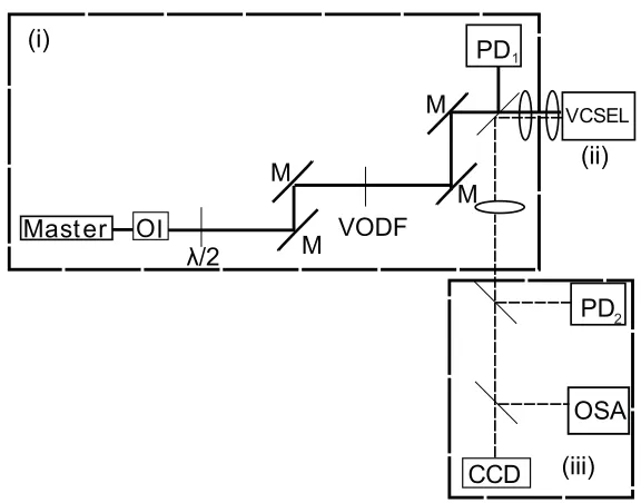
The experimental setup used for the generation of two-dimensional localized structures is shown in Fig. 1. The setup contains three main parts. (i) Injection: the holding beam is provided by a commercial Sacher Lasertechnik TEC100-0960-60 External Cavity Diode Laser (Master) isolated with OFR IO5-TiS2-HP optical isolator (OI). The long term electrical and temperature stability of this laser are less than 20 mA RMS and 0.05°C, repectively. The wavelength (fre-quency) sensitivity is 0,695 nm par 100V with piezo actuator. Due to the power limitation of
the tunable injection laser, we do not implement a writing beam. A half wave plate (λ/2) is
used to tune the linear polarization. The injection beam power is tuned using a variable optical density filte (VODF). The detuning between the master laser and the VCSEL is define as θ=νin j−νslave,whereνin j is the frequency of the injection beam, andνslave the frequency of the strongest peak in the spectrum of the standalone VCSEL. It is experimentally tuned by changing the wavelength of the injection beam. The beam waist is define as the diameter of the smallest circle in the plane of propagation of the injection beam containing half of the beam power when it encounters the VCSEL. The beam waists used in our measurements are 100μm and 50μm. The power of the source is monitored by a Newport 818-SL photodiode connected to a Newport 2832-C powermeter. This system yields about 100 Hz data acquisition and
trans-fer rate. This photodiode is indicated PD1in Fig. 1. (ii) Nonlinear material: we use a 80μm
diameter, bottom emitting InGaAs multiple quantum well VCSEL [64], which has a threshold
current of 42.5 mA at 25.0◦C. The response time scale involved in the space-time dynamics of
the material (≈ps) and carriers (≈ns) are much faster than the thermal time scale (≈μs). (iii)
Detection of the VCSEL output: the fiel emitted by the VCSEL is analyzed using an ANDO
AQ6317-B optical spectrum analyzer (OSA). This device has a resolution of 0.02nm at 980nm.
A CCD camera is used to monitor the near fiel output profil of the VCSEL. For detection
of the output VCSEL power we use the photodiode PD2, which is identical to the photodiode
PD1.
2.2. VCSEL characteristics
Measurements of the VCSEL optical spectrum and the near fiel profil as a function of current and optical injection power are performed. The standalone device is studied as well.
To characterise the standalone VCSEL, we firs measure its optical spectrum as a function of current. The optical spectra of the solitary VCSEL as a function of injected current in ver-tical and horizontal polarization directions are depicted in Fig. 2. In the verver-tical polarization optical spectrum, the threshold current and the current-induced thermal red shift are indicated with solid white lines as shown in Fig. 2(a). From these optical spectra, we see that the power is mostly emitted along the vertical polarization direction. However, in the horizontal polariza-tion optical spectrum there is no visible threshold, as shown in Fig. 2(b). Therefore, close to threshold, the VCSEL emits linearly polarized light.
The near fiel emission profil of the VCSEL is shown in Fig. 3(a). This measurement has
been obtained forI=45.0mA>Ith=42.0mA, whereIthis the lasing threshold at 25◦C. The
corresponding optical spectrum is plotted in Fig. 3(b). These measurements have been
per-formed at a constant temperature ofTsub=25.0◦C. The near fiel image in Fig. 3(a) shows
1
2
I
(i)
[image:6.612.162.450.106.332.2](iii)
(ii)
Fig. 1. Experimental setup schematic. The full line is the path of the light from the master laser, whereas the dashed line is the path followed by the light from the VCSEL. (i): injec-tion preparainjec-tion and monitoring; Master: master laser, OI: optical isolator,λ/2 : half wave plate, M: mirror, VODF: variable optical density filter (ii) : VCSEL; (iii): analysis branch; PD: photodiode, OSA: optical spectrum analyser.
[image:6.612.137.480.468.588.2]Output Power [dBm]
Wavelength [nm] -30
-40
-50
-60
-70
978 980 982 984
[image:7.612.165.450.78.184.2]a) b)
Fig. 3. Solitary VCSEL characteristics obtained forI=45.0mA andTsub=25.0◦C. (a)
near fiel profil in the transverse plane. Black corresponds to high optical power whereas white corresponds to low optical power. (b) is the corresponding optical spectrum.
2.3. Optically injected VCSEL
Finally, we examine the spectrum of the VCSEL submitted to optical injection with a
polar-ization direction parallel to the one of the VCSEL. We set the VCSEL current atI=45.0mA
and we keep the substrate temperature constant atTsub=25.0◦C. Injection locking requires
high enough injected power as well as a negative and small enough frequency detuning [66].
For this purpose, we need an injection wavelength greater than 982.91nm. The measurement
of the optical spectra is shown in Fig. 4. These spectra have been measured for two values
of the injected power determined by the photodiode PD1. When the injection beam power is
Pin j=850μW, the VCSEL is frequency pulled towards the master laser frequency which is
in-dicated by a short vertical arrow, as shown in Fig. 4(a). The near fiel emission profil changes, even if the fl wer-like mode has not disappeared from the emitting surface of the VCSEL. In this case, there is no injection locking of the VCSEL. However, for an injection power of
Pin j=2.04 mW, the VCSEL is locked to the master laser as shown in Fig. 4(b).
Fig. 4. Dashed lines: optical spectra of the free running VCSEL obtained forI=45.0mA
andTsub=25.0◦C. Solid lines: optically injected VCSEL withλin j=983.24nm (indicated
by a vertical arrow) and injection power of (a)Pin j=850μW and (b)Pin j=2.04 mW. The
insets are near fiel images of the optically injected VCSEL.
3. Spontaneous formation of localized structures in an optically injected VCSEL
[image:7.612.157.463.426.537.2]may then undergo a bistable behavior when either varying the injected beam power or the VC-SEL current. In addition, we study the formation of 2-dimensional LSs for different values of detuning and also for different beam waists. All experimental measurements have been per-formed when the VCSEL operated in an injection locked regime as in Fig. 4(b).
We firs investigated LSs bistable with the injection power for a f xed value of the detuning
parameterθ=−174 GHz and for a f xed value of the injection beam waist 100μm. The
exper-imental results are summarized in the bistable curve in Fig. 5(a). The VCSEL output power as a function of the injected beam power, which is shown in this figure undergoes a bistable be-havior between a single LS (i) and a two LSs (ii) states, as shown in Fig. 5(a). The experimental procedure to obtain LSs consists of increasing the injection power, and, just as the locking re-gion is reached, a single LS appears. Then, as we further increase the optical injection power by tuning the variable optical density filte (VODF), we observe transition from a single LS state towards a two-LSs state. This behavior corresponds to a spontaneous switching on. To realise the switching off, we decrease the injection power. The two LSs persist until the system reaches the switching down point, over which the system relaxes to the single peak state. The density plot of both 1-LS and 2-LSs near fiel are recorded by using a CCD camera. Cross sections of the single and the two-LSs states near-fiel are shown in Figs. 5(b) and 5(c). A similar behavior of switching on and off has been observed while the detuning parameter was
θ=−157GHz and the beam waist 100μm. A fundamental characteristic of LSs is that it has
9.5 10.0 10.5 11.0 11.5 6.0
6.5 7.0 7.5
a)
Pinj [mW]
V
C
SE
L
output pow
e
r [m
W
]
(i)
[image:8.612.157.460.320.470.2](ii)
Fig. 5. Bistability between one and two-peaked LSs inside the near fiel of the VCSEL as a function of the optical injection power. (a): power emitted by the VCSEL as a function
of the optical injection power forθ=−174GHz and a beam waist of 100μm. The insets
(i) and (ii) respectively represent near fiel profile on the higher and lower branch of the hysteresis. (b) and (c): one dimensional profile along the horizontal line drawn on the aforementioned insets.
an oscillatory tail, which decays exponentially with the distance to the center of the LS. This behavior has been shown experimentally with other optical systems [34, 35, 67]. We recover this fundamental property in VCSELs. An example of such a behavior is illustrated in Fig. 6.
In order to increase the optical power on the VCSEL, we decreased the beam waist to 50μm
and the detuning toθ=−118GHz. We could then reach a multipeak regime as shown in Fig.
7(a). In this case, three states can exist, with a bound state of two LSs (2P), this bound state accompagnied with a single peak localized structure (3P), or a four-peak LS (4P). Cross sections along the vertical lines in the insets Fig. 7 (2P), (3P) and (4P) coresspond to the aforementioned
states. A bistable behavior has also been observed while the detuning wasθ=−146GHz.
Fig. 6. Cross sections along the solid lines indicated in Fig. 5(a), (i) and (ii). The dashed line is the state (ii)(lower branch of the hysteresis), whereas the full line is the system with a LS (upper branch of the hysteresis).
b)
c) d)
5 6 7 8 9
2.5 3.0 3.5
Optical power in[mW]
O
ptic
a
l pow
e
r out [m
W
]
(2P) (4P)
(3P)
20 40 60 80
20 40 60 80
20 40 60 80
a)
Fig. 7. Bistability between three states inside the near fiel of the VCSEL as a function of the optical injection power. (a): power emitted by the VCSEL as a function of the optical
injection power forθ=−118GHz and 50μm injection beam waist. The insets (2P) and
[image:9.612.118.495.315.602.2]We set the beam waist at 100μm and the optical injection power at 17mW. When varying the VCSEL current, we observe bistability of a LS. An example of such a behavior is illustrated in Fig. 8(a). Cross sections along the vertical lines in Figs. 8(b) and 8(c) correspond to the near fiel profile of the insets (i) and (ii), respectively.
Fig. 8. Bistability between two states inside the near fiel of the VCSEL as a function of the VCSEL current. (a): power emitted by the VCSEL as a function of the VCSEL current
for 100μm and 17mW optical injection beam waist and power, respectively. The bistable
[image:10.612.127.488.137.315.2]4. Conclusions and perspectives
To conclude, we report experimental evidence of spontaneous formation of spatially localized structures in a 80μm diameter VCSEL submitted to optical injection. Different detunings be-tween the frequencies of the injection beam and the VCSEL have been investigated, as well as different beam waists. This behavior occurs in two different bistability regimes by varying either the optical injection power or the VCSEL current.
In future work, we plan to investigate experimentally the role of delay feedback, and estabilsh a link with our predictions on a full rate equation model of broad area VCSELs [56, 57, 59] subject to simultaneous time-delayed feedback and optical injection. This study showed that the modulation instability region strongly depends on both the feedback strength and the feedback phase. Furthermore, the optical feedback induces traveling wave instabilities in the system, as well as spontaneous motion with a constant velocity of a single peak LS.
The analysis of local polarization dynamics [63] in the transverse plane of the resonator, the occurrence of polarization patterns and possibility the realization of LSs between two po-larization modes can be of interest as well. Studies of vector solitons in popo-larization will be theoretically carried out using the spin-fli model of VCSELs, and implemented experimen-tally.
Acknowledgments
M.T. received support from the Fonds National de la Recherche Scientifiqu (Belgium). This research was partially supported by EU FP7 ICT FET Open HIDEAS and by the Interuniver-sity Attraction Poles program of the Belgian Science Policy Office under grant IAP P7-35