Abstract—The input coupler is an important component for a
microwave amplifier. In this paper, a side-wall single-hole input coupler for a W-band gyrotron travelling wave amplifier (gyro-TWA) that operates at the frequency range of 90 - 100 GHz was designed and measured. Instead of using a cutoff waveguide, a broadband Bragg-type reflector with a small spread in phase was optimized for use as part of the input coupler. The minimum radius of the reflector was two times the size of a cutoff waveguide which reduced the possibility for some of the beam electrons being collected in this section and lost to the amplifier interaction region.
Index Terms— gyro-TWA, input coupler, Bragg reflector.
I. INTRODUCTION
yro-devices are high-power coherent radiation sources based on the electron cyclotron instability. The travelling wave amplifiers (gyro-TWAs) are one kind of gyro-device that can be used in various applications including electron paramagnetic resonance spectroscopy, high resolution radar, deep space communication and plasma diagnostics. A high-power wide-frequency-tunable source has significant advantages in these applications. However, to achieve broad-band amplification is challenging for the gyro-devices. For a conventional gyro-TWA using smooth waveguide as the beam-wave interaction region, broad-band amplification only occurs far-away from the cutoff frequency, which requires high beam voltage as well as suffering from a high sensitivity to the electron beam quality.
The wide frequency tuneability can be achieved by using a helically corrugated waveguide (HCW) that has a periodic corrugation on a smooth circular waveguide, as shown in Fig. 1(a). From the Floquet theory, the periodic structure has an infinite number of spatial harmonics [1]. From the coupled-mode theory [2], [3], the axial and azimuthal periodicities in the HCW allow the coupling of two different
This work was supported by the Engineering and Physical Sciences Research Council (EPSRC) U.K. under Research Grant EP/K029746/1. The EPSRC Engineering Instrument Pool is gratefully acknowledged for providing the Vector Network Analyzer (VNA) used in the experiments. The authors would like to thank Alan Ruddell for his assistance in setting up and installing the VNA in the laboratory.
L. Zhang, W. He, C. R. Donaldson, J. R. Garner, P. McElhinney and A. W. Cross are with the Department of Physics, Scottish Universities Physics Alliance (SUPA), University of Strathclyde, Glasgow G4 0NG, U.K. (e-mail: liang.zhang@strath.ac.uk; w.he@strath.ac.uk; craig.donaldson@strath.ac.uk; j.garner@strath.ac.uk;paul.mcelhinney@strath.ac.uk; a.w.cross@strath.ac.uk).
modes (mode 1 and 2 in Fig. 1(b)) in circular waveguide to generate new eigen modes (W1 and W2
k
). The synchronism conditions for both of the axial and azimuthal directions are
1 - k2 = 2π / d, m1 - m2
where d and m are the axial and azimuthal periodicities of the waveguide, k
= m (1)
1, k2 are the axial wave numbers and m1, m2 are the azimuthal indices of the two coupling modes. If the dimensions of the HCW are properly designed, the eigenmode W1 is able to achieve a constant large group velocity over a large range of axial wavenumbers around zero, as shown in Fig. 1(b). This ensures the gyro-TWA has broadband amplification (ω1 to ω2
Gyrotron backward wave oscillators (gyro-BWOs) and gyro-TWAs based on HCWs have demonstrated excellent results in achieving high-power and wide frequency tuneability [4]-[6]. A W-band gyro-BWO with a HCW achieved a maximum output power of 12 kW. The frequency tuning band in the measurement was 88.0 - 102.5 GHz by adjusting the cavity magnetic field [7]. A W-band gyro-TWA that shares the same cusp electron gun, the solenoid system and microwave output window with the gyro-BWO is currently being experimentally studied. It is predicted to achieve a saturated gain of 35 dB, and an output power of 5 kW in the frequency band of 90 - 100 GHz when driven by a 40 kV, 1.5 A, annular-shaped large-orbit electron beam [8].
) as well as less sensitivity to the velocity spread of the electron beam.
(a)
(b)
Fig. 1 (a) The 3D model of a HCW, and (b) mode coupling in the HCW. The operating mode W1 has a constant large group velocity over a large range of
axial wavenumbers around zero. d is the axial period of the HCW.
Design and Measurement of a Broadband
Side-wall Coupler for a W-band Gyro-TWA
Liang Zhang, Wenlong He, Craig R. Donaldson, Jason R. Garner, Paul McElhinney and Adrian W.
Cross
[image:1.612.316.563.506.710.2]In contrast to the gyro-BWO, the gyro-TWA requires an input microwave signal for amplification. The input signal is coupled into the system between the electron gun and the interaction region from the radial direction. The configuration of the side-wall input couplers may be different depending upon the required operating modes for the interaction, but can be categorized as a single-hole or a multiple-small-aperture type coupler. Both types have been used in the gyro-TWA experiments. The multiple-small-aperture coupler is able to achieve good coupling over a narrow bandwidth (about 2%) and the performance degrades as the bandwidth increases. A multiple-small-aperture input coupler designed for a Ka-band gyro-TWA achieved about -2 dB transmission coefficient with 17% bandwidth from 33 - 39 GHz [9]. At W-band, higher loss is expected due to the smaller coupling holes (about 0.3 mm). A single-hole coupler with a cutoff waveguide achieved 20% bandwidth at X-band [10]. However it is limited by the usage of the small-radius cutoff waveguide at high operating frequency.
So far, there are no input couplers reported that operate at W-band that achieve high transmission as well as broad bandwidth. In this paper, the single-hole coupler is discussed as it has the advantage of compact structure with a small area required to be brazed together to seal the vacuum, which is more suitable for the W-band gyro-TWA under development due to the space limitation between the cavity coil and the vacuum jacket. The input coupler with a Bragg reflector was optimized to achieve a maximum transmission from the input TE10 mode in the rectangular waveguide to the TE11
This paper is organized as follows. Section II describes the T-junction side-wall coupler with cutoff waveguide. Section III presents the design of the side-wall coupler with a broadband Bragg reflector. In Section IV, the construction and measurement results of the Bragg reflector as well as the input coupler are reported and discussed. Section V contains the conclusion.
mode in the circular waveguide. The preliminary idea of the proposed coupler was introduced in [11]. In this present paper, a detailed study of the principle, the simulation and the optimization of the coupler is reported. The simulation results have been verified by measurement using a vector network analyzer (VNA) and good agreement achieved.
II. SINGLE-HOLE SIDE-WALL COUPLER WITH CUTOFF SECTION
The general geometry of the single-hole side-wall coupler is a rectangular-to-circular T-junction. It is a basic microwave structure that can be used in applications such as an ortho-mode transducer (OMT) [12], polarizer and microwave filter [13]. The scattering parameters of the rectangular-to-circular T-junction can be efficiently calculated by several methods, such as finite-difference time-domain (FDTD), finite-element method (FEM), or mode matching method [14], [15]. If only the transmission coefficient from the TE10 mode of the rectangular waveguide to the TE11
However, the T-junction is a symmetrical structure between
port 2 and 3, which means the transmission coefficient between port 1 and 2 (S
mode of the circular waveguide needs to be calculated, a simple equation as described in paper [13] can be used to quickly predict the performance.
12) will only have a maximum value of -3 dB (half of the input power). To improve the transmission coefficient between port 1 and 2 in the T-junction, a cutoff waveguide is usually used at port 3. The cutoff waveguide can also stop the microwave radiation from propagating towards the electron gun region preventing it from interfering with the electron beam. The general geometry of the T-junction with a cutoff waveguide with the definition of the geometry is shown in Fig. 2. The transmission coefficients S21 with different radii
[image:2.612.316.562.234.311.2]Rcand lengths L of the cutoff waveguide are shown as Fig. 3. In the simulation, the radius R is 1.30 mm which is same size as the mean radius of the HCW. The dimensions a and b are 1.20 mm and 1.72 mm, respectively, which provide the optimal S12 of the T-junction over the frequency band of 90 - 100 GHz.
Fig. 2 The geometry of the T-junction with a cutoff waveguide with parameters' definition.
(a)
(b)
Fig. 3 The transmission coefficient as a function of (a) Rc when L=0 mm, (b) of
[image:2.612.316.564.342.712.2]Fig. 3(a) shows that the S21 is improved as the Rc value reduces when L=0. A simple explanation is less microwave power will propagate to port 3 due to the geometry discontinuity of the circular waveguide step. By the principle of the conservation of energy, this power will either be reflected back to port 1 or travel to port 2 to enhance the transmission power. A smaller Rc means a higher reflection from the waveguide step, and a higher transmission coefficient can be achieved. The waveguide short with Rc
Fig. 3(b) shows that the bandwidth increases as the length of the cutoff waveguide reduces when a waveguide short (R
= 0 has an unity reflectivity in all the frequencies and has the best transmission coefficient. If the operating bandwidth of the coupler is defined by the frequency range of -1dB transmission, the radius of the cutoff waveguide needs to be smaller than 0.68 mm to achieve a full bandwidth of 90 -100 GHz.
c=0) is used. In this case, the phase response of the circular waveguide is the only parameter that affects the bandwidth. The phase of the TE11 mode in a circular waveguide with radius R and length
L is -kz·L, where kzis the axial wavenumber of the TE11
P(L,ω) = -2k
mode. The waveguide short has a constant phase response of π. The overall phase response by the circular waveguide with length L and the waveguide short is
z ·L + π = -2( (ω/c)2 - (1.841 / R)2 )1/2
The phase spread in the operating frequency range can be defined as
·L+ π (1)
Ps(L) = 2π - ( | P(L,ω1) | + | P(L,ω2 where ω
[image:3.612.51.297.511.666.2]) | ) (2) 1 and ω2 are the start and end frequency in equation (2). Fig. 4 shows the relation between the phase spread and the bandwidth for different waveguide lengths L. The phase spread becomes larger as L increases, and the larger the phase spread is, the narrower the bandwidth will be. The maximum bandwidth of about 19% can be achieved when L=0, where P(0,ω) is a constant and no phase spread exists. Another useful result from Fig. 3(b) is the center frequency in the bandwidth shifts as the length L of the waveguide changes, which allows the coupler to have some tuning capability.
Fig. 4 The correlations between the phase spread, the bandwidth and the length
L.
III. SIDE-WALL COUPLER WITH BRAGG REFLECTOR
The cutoff waveguide is a general solution to improve the transmission coefficient for the input coupler. The only
requirement is the radius of the cutoff waveguide needs to be sufficiently small. For a low frequency microwave vacuum electronic device, such as the X-band gyro-BWO/TWA, the requirement is easier to satisfy while keeping a high electron beam transportation rate. For the W-band gyro-TWA, the average radius of the annular electron beam is about 0.37 mm at a beam alpha of 1.56 [16]. The beam radius is even larger in the input coupler region as the magnetic field is smaller. From the simulation results presented above, if a cutoff waveguide was used in the input coupler region then the electron beam would be separated by a distance of less than 0.3 mm from the inner surface of the cutoff waveguide. It will be useful to have space for the electron beam to pass, as this alleviates the alignment problem of the beam in the diode region. Ideally a waveguide structure with a large inner radius but having similar characteristics to a waveguide short is required. From the analysis and discussion in Section II, this requirement can be specified by a high reflection coefficient and small phase spread over the operating frequency band. The phase spread has greater effect than the reflection coefficient.
(A) Design of the Bragg reflector
Based on the general mode-coupling structure mentioned in the introduction, a waveguide with only axial periodicity also allows one mode to couple with its spatial harmonic. In this case, the azimuthal resonance condition will be automatically satisfied. The axial resonance condition becomes 2k1
Among the various axial periodic structures, the simplest structure is the periodic rectangular-corrugation waveguide which includes two circular waveguide sections with different radiiin one period. The mode-selective Bragg reflector [17] based on the rectangular corrugation waveguide can achieve a high reflection, however the bandwidth is small and not able to cover the frequency band of the gyro-TWA. It has been shown that the bandwidth of the Bragg reflector can be improved by varying the corrugation profile. A 13-section reflector has been designed to operate in the frequency range 8.0 - 9.5 GHz for an X-band gyro-BWO to enable electron beam propagation and to reflect the microwave radiation in the forward direction [18]. Further simulations show that more corrugation sections will achieve larger bandwidth and higher reflection while the drawback is a larger ohmic loss.
=2π/d, which is also called “the Bragg resonance condition”. A strong mode-selective reflection that scatters the incident wave coherently into a backward wave can be achieved. Also this axial periodic structure can be overmoded therefore a large radius is possible. It will be very useful in the high frequency applications as the dimensions can be relatively large to release the tolerance requirement. Therefore, it has great potential to replace the waveguide short used in the coupler if a small phase spread can be achieved as well.
was employed to simulate such a waveguide structure. A multiple-objective optimization using a genetic algorithm was used to search for a broadband reflector with variable corrugation depths. Two goal functions were used in the optimization. One was to maximize the reflection, and the other was to minimize the phase spread. The equations are
2 1/ 2
1 11
2 11 11
( ) ( [ ( , ) 1] / )
( ) MAX(UNWRAP( ( )) MIN(UNWRAP( ( ))
N
F
f x A x F N
f x P x P x
= −
= −
∑
(3)where xare the parameters to be optimized. In this case, they are the dimensions of the reflector. F is the frequency index in the calculated frequency range, N is the number of the frequency samples, A11 is the reflection coefficient of the S11 and P11 is the phase of S11
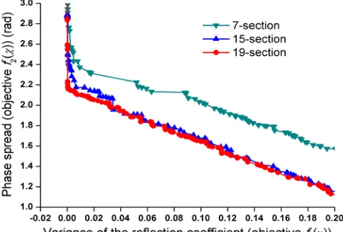
Fig. 5 shows the Pareto fronts of the goal functions in different numbers of corrugation sections. A high reflection can be achieved (f
. The value range of the period can be simply calculated from the Bragg resonance condition and the minimum radius of the corrugation section was set as the same as the mean radius of the interaction region.
[image:4.612.313.583.76.259.2]1(x) close to 0) if the phase spread does not need to be considered. However, a very high reflection as well as a small phase spread cannot be achieved at the same time. The practical design needs to tradeoff between the goal functions. Increasing the number of corrugation sections will help to get a better performance but not significantly better after this number exceeds 15.
Fig. 5 The Pareto fronts of the multiple-objective optimization with different corrugation sections.
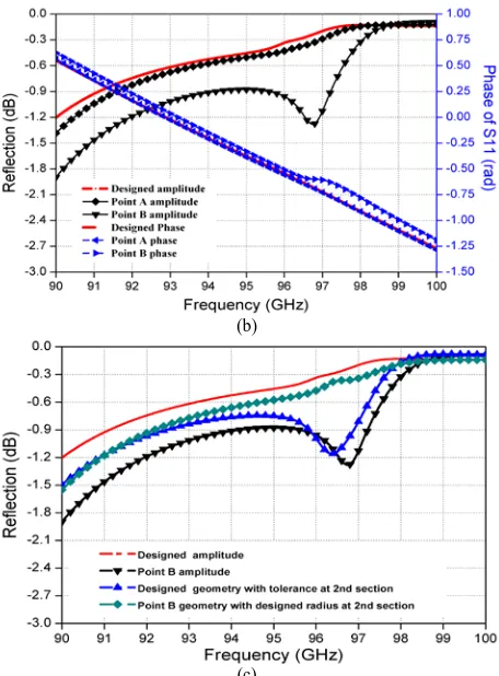
The optimum geometry of the Bragg reflector was chosen to have a balanced performance of the reflectivity and phase spread, as shown in Fig. 6. The dimensions of the corrugation radii are listed in Table 1. The phase spread is about 1.82. From Fig. 4, such a phase spread will give rise to a bandwidth larger than 10 GHz and is sufficient to cover the required frequency band. The tolerance sensitivity of the Bragg reflector was also studied by an optimization routine. In the optimization, all the dimensions were allowed to have random tolerances within ±20 μm and the target was to maximize the goal functions in (3). The Pareto front is shown as Fig. 7(a). The reflectivity becomes worse with the tolerance applied. The tolerance will generally result in a larger phase spread while it also is possible to get an even smaller value. However, the difference is relatively small,
with a maximum change of 0.03. Fig. 7(b) shows the comparison of the simulation results for the designed geometry and the ones at point A and B in Fig. 7(a). At point A, the radii of the 3rd to 6th sections are nearly with maximum tolerance of 20 μm. It results in larger phase spread; however it only has a small effect on the reflectivity. The dimensions at point B shows the last few sections have a bigger effect on the reflectivity. With the appearance of a spike at 97 GHz, the phase spread can be even smaller. Further simulations show that the spike is mainly caused by tolerance from the 2nd corrugation section. As shown in Fig. 7(c), the spike appears when using the designed geometry but with tolerance at the 2nd corrugation section, and it disappears when using the geometry with tolerance at point B except the designed radius at the 2nd corrugation section. The tolerance from the other corrugation sections has less effect on the amplitude and the phase response of the Bragg reflector.
Fig. 6 The geometry of the optimized 16-section Bragg reflector (unit in mm).
(a) TABLEI
DIMENSIONS OF THE DESIGNED AND MACHINED BRAGG REFLECTOR
the units are all in mm.
Section
number 1 2 3 4 5 6 7 8
Designed
diameter 2.60 4.16 3.50 4.64 4.72 3.44 3.96 4.44
Tolerance
point A 2.600 4.162 3.540 4.677 4.760 3.480 4.000 4.402 Tolerance
point B 2.600 4.123 3.538 4.674 4.760 3.480 3.950 4.402 Measured
diameter 2.60 4.26 3.61 4.73 4.80 3.47 4.03 4.50
Section
number 9 10 11 12 13 14 15 16
Designed
diameter 3.74 4.96 4.52 4.42 4.56 4.18 5.02 4.52
Tolerance
point A 3.707 5.000 4.497 4.455 4.536 4.214 5.013 4.483 Tolerance
point B 3.739 4.997 4.514 4.427 4.532 4.216 5.006 4.500 Measured
[image:4.612.51.293.372.536.2](b)
(c)
Fig. 7 (a) The Pareto fronts of the tolerance sensitivity, (b) the comparison of the performance with designed parameters and the values at points A and B and (c) detail tolerance study on section 2.
(B) side-wall coupler with Bragg reflector
The input coupler composed of the reflector and the T-junction was simulated using CST microwave studio. A good transmission of about -0.4 dB can be achieved over the frequency band of 90-100 GHz using the designed dimensions of the broadband reflector, as shown in Fig. 8(a). The simulation of the coupler with the designed Bragg reflector showed an average transmission coefficient of -0.4 dB over the frequency band. When considering the tolerance, the average transmission is still better than -0.6 dB, which meets the design criteria of the coupler for the gyro-TWA. It also confirms that the reflectivity of the Bragg reflector does not have a significant impact on the coupler.
Fig. 8 The performance of the designed coupler and with tolerance at point A and B.
IV. CONSTRUCTION AND MEASUREMENT
The reflector was manufactured using an electroforming method. An aluminum former with the inner cross-section of the waveguide was firstly constructed by a computer numerical control (CNC) machine and then copper was grown on it. The aluminum mandrel was later dissolved away to form the copper waveguide. Before electroforming, the dimensions of the reflector were measured and then simulated. The comparisons of the designed and measured dimension of the broadband reflector are shown in Table 1. Almost all the radii of the corrugation sections in the measurement are larger than the designed values, and the averaged machining error was about 0.1 mm. Generally a well calibrated CNC machine should be able to achieve a machining accuracy of ±20 μm if operated by an experienced technician.
[image:5.612.60.288.49.358.2]From the simulation, although the magnitude of the reflection has a different trend with the one designed, the phase spread of the two structures are similar with a phase shift of about 17 degrees. This resulted in a shift of the central frequency. The measured results shown in Fig. 9 agree well with the simulation results using the actual dimensions. The spike at 95 GHz is mainly caused by the tolerance at the 2nd section.
Fig. 9 The S-parameters of the optimized 16-section Bragg reflector.
With the actual dimensions, the center frequency of the bandwidth is down shifted, which means the lower frequency side has an even better transmission while the higher frequency side becomes worse. From the analysis in section II, it is possible to shift the center frequency by reducing slightly the length of the first section.
[image:5.612.316.564.331.496.2] [image:5.612.54.293.562.712.2]if considering the loss of the input coupler and the relatively big machining tolerance, such performance is quite acceptable for use in the W-band gyro-TWA. It also proves that the reflector with periodic corrugations is not a tolerance-sensitive waveguide structure. Therefore with a smaller machining tolerance this design could be used for higher frequency applications.
(a)
(b)
(c)
Fig. 10 (a) The measurement setup, (b) the transmission coefficient and (c) the reflection coefficient of the input coupler.
V. CONCLUSION
In this paper, a side-wall single-hole coupler based on a rectangular-to-circular T-junction and a broadband Bragg-type reflector was designed and measured. The relations between the bandwidth and the phase spread were analyzed numerically. It was used as one of the goal functions to optimize the
dimensions of the broadband reflector. The measurement of the input coupler showed an average -1.0 dB transmission over the desired frequency band (90-100 GHz), which is acceptable to be used in the W-band gyro-TWA experiment. The proposed input coupler has much larger radius compared with the one using a cutoff waveguide, therefore greatly relaxing the strict alignment requirement of the gyro-TWA. The proposed coupler has potential for further improvements, such as using a more precise CNC machine to reduce the machining tolerance. Also as the Bragg reflector has a relatively large tolerance allowance, it is possible to simplify the geometry by combining similar radii to reduce the machining difficulty, such as combining corrugation sections 4 and 5, and corrugation sections 11, 12 and 13.
REFERENCES
[1] R. E. Collin, “Field Theory of Guided Waves, in Series of Electromagnetic Waves,” second edition, New York: IEEE Press, 1991. [2] G. G. Denisov and M. G. Reznikov, “Corrugated Cylindrical Resonators
for Short-wavelength Relativistic Microwave Oscillators," Radiophys. Quantum El., vol. 25, no. 5, pp. 407-413, 1982.
[3] L. Zhang, W. He, K. Ronald, A. D. R. Phelps, C. G. Whyte, C. W. Robertson, A. R. Young, C. R. Donaldson, and A. W. Cross, "Multi-Mode Coupling Wave Theory for Helically Corrugated Waveguide," IEEE Trans. Microw. Theory Techn., vol. 60, no. 1, pp. 1-7, Jan. 2012.
[4] W. He, A. W. Cross, A. D. R. Phelps, K. Ronald, C. G. Whyte, S. V. Samsonov, V. L. Bratman, and G. G. Denisov, "Theory and Simulations of a Gyrotron Backward Wave Oscillator Using a Helical Interaction Waveguide," Appl. Phys. Lett., vol. 89, pp. 091504, 2006. [5] V. L. Bratman, A. W. Cross, G. G. Denisov, W. He, A. D. R. Phelps,
K. Ronald, S. V. Samsonov, C. G. Whyte, and A. R. Young, "High-Gain Wide-Band Gyrotron Traveling Wave Amplifier with a Helically Corrugated Waveguide," Phys. Rev. Lett., vol. 84, no. 12, pp. 2746-2749, Mar. 2000.
[6] S. V. Samsonov, G. G. Denisov, I. G. Gachev, A. G. Eremeev, A. S. Fiks, V. V. Kholoptsev, G. I. Kalynova, V. N. Manuilov, S. V. Mishakin, and E. V. Sokolov, "CW Ka-Band Kilowatt-Level Helical-Waveguide Gyro-TWT," IEEE Trans. Electron Devices, vol. 59, no. 8, pp. 2250 - 2255, Aug. 2012.
[7] W. He, C. R. Donaldson, L. Zhang, K. Ronald, P. McElhinney, and A.W. Cross, "High Power Wideband Gyrotron Backward Wave Oscillator Operating towards the Terahertz Region," Phys. Rev. Lett., vol. 110, pp. 165101, Apr. 2013.
[8] W. He, C. R. Donaldson, L. Zhang, P. McElhinney, A. D. R. Phelps, K. Ronald, and A. W. Cross, "Latest experiments of W-band gyro-BWO using helically corrugated waveguides," 38th International Conference on Infrared, Millimeter, and Terahertz Waves (IRMMW-THz), Mainz, Germany, September 1-6, 2013.
[9] D. E. Pershing, K. T. Nguyen, J. P. Calame, B. G. Danly, B. Levush, F. N. Wood, and M. Garven, "A TE11
[10] C. G. Whyte, K. Ronald, A. R. Young, W. He, C. W. Robertson, D. H. Rowlands, and A. W. Cross, "Wideband Gyro-Amplifers", IEEE Trans. Plasma Sci., vol. 40, no. 5, pp. 1303-1310, May 2012.
Ka-Band Gyro-TWT Amplifier With High-Average Power Compatible Distributed Loss," IEEE Trans. Plasma Sci., vol. 32, no. 3, pp. 947 - 956, Mar. 2004.
[11] L. Zhang, W. He, C. R. Donaldson, K. Ronald, P. McElhinney, A. W. Cross, "An input coupler for a W-band gyro-TWA," 6th UK, Europe, China Millimeter Waves and THz Technology Workshop (UCMMT), Rome, Italy, Sep. 9-11 2013, and J. R. Garner, L. Zhang, C. R. Donaldson, P. McElhinney, "An input coupler for a W-band gyro-TWA," 1st Annual Active and Passive RF Devices Seminar, Glasgow, U.K., Oct. 29 2013, pp.47 - 50.
[12] J. Zheng and M. Yu, “Rigorous mode-matching method of circular to off-center rectangular side-coupled waveguide junctions for filter applications,” IEEE Trans. Microw. Theory Techn., vol. 55, no. 11, pp. 2365-2373, Nov. 2007.
[image:6.612.49.300.136.631.2][14] P. Krauss and F. Arndt, “Rigorous mode-matching method for the modal analysis of the T-junction circular to side coupled rectangular waveguide,” IEEE MTT-S International Microwave Symposium Digest, vol. 3, pp. 1355-1358, Orlando, USA, May 1995.
[15] N. Yoneda, M. Miyasaki, T. Nishino, H. Asao, H. Nakaguro, and S. Betsudan, “Analysis of circular-to-rectangular waveguide T-junction using mode-matching technique,” Electronics and Communications in Japan (Part II: Electronics), vol. 80, no. 7, pp: 37-46, Jul. 1998. [16] C. R. Donaldson, W. He, A. W. Cross, F. Li, A. D. R. Phelps, L. Zhang,
K. Ronald, C. W. Robertson, C. G. Whyte, and A. R. Young, “A cusp electron gun for millimeter wave gyrodevices”, Appl. Phys. Lett., vol. 96, 141501, 2010.
[17] C. K. Chong, D. B. McDermott, M. M. Razeghi, N. C. Luhmann, Jr. J. Pretterebner, D. Wagner, M. Thumm, M. Caplan, and B. Kulke, “Bragg reflectors,” IEEE Trans. Plasma Sci., vol. 20, no. 3, pp. 393–402, Mar. 1992.
[18] L. Zhang, W. He, A.W. Cross, A.D.R. Phelps, K. Ronald and C. G. Whyte, “Design of an Energy Recovery System for a Gyrotron Backward-Wave Oscillator,” IEEE Trans. Plasma Sci., vol. 37, no. 3, pp: 390-394, Mar. 2009.
[19] G. L. James, “Analysis and design of TE11-to-HE11 corrugated
cylindrical waveguide mode converters”, IEEE Trans. Microw. Theory Techn., vol. 29, no. 10, pp. 1059-1066, 1981.
Liang Zhang received the B.Sc. degree in
applied physics from the University of Science and Technology of China, Hefei, China, in 2004 and the M.Sc. degree in application of nuclear techniques from the China Academy of Engineering Physics, Chengdu, China, in 2007, and the Ph.D. degree in physics from the University of Strathclyde, Glasgow, UK in 2012.
He is currently a Research Associate with the Scottish Universities Physics Alliance, Department of Physics, University of Strathclyde. His main research interests include pulse-power technology, and Gyrotron-TWA/backward-wave oscillators.
Wenlong He received the B.Sc. degree in
physics from Soochow University, Jiangsu, China, in 1983, the M.Sc. degree in accelerator physics from the China Academy of Engineering Physics, Chengdu, China, in 1988, and the Ph.D. degree in relativistic electron beams and masers from the University of Strathclyde, Glasgow, U.K., in 1995.
He is currently a Senior Research Fellow with the Scottish Universities Physics Alliance, Department of Physics, University of Strathclyde. His main research interests include relativistic electron beams, Gyrotron-TWA/backward-wave oscillators, CARMs, FELs, and other high power microwave and terahertz devices.
Craig R. Donaldson received the B.Sc.
(Hons.) degree in physics, the M.Sc. degree in high power RF and PhD. degrees from the University of Strathclyde, Glasgow, U.K., in 2005, 2006 and 2009, respectively, from the University of Strathclyde.
He has since continued to work as a Research Fellow with the Department of
Physics, University of Strathclyde, with his main research interests in high frequency gyro-TWA/BWO's and electron beam generation.
Jason R. Garner received his B.Sc. (Hons) degree in Physics in 2010 and the M.Sc. degree in High Power Radio Frequency Science and Engineering in 2012, both from the University of Strathclyde, Glasgow, UK.
He is currently a PhD Student with the Scottish Universities Physics Alliance working within the Department of Physics at the University of Strathclyde. His main research interests include the design of passive components for mm-wave gyro-devices and gyro-TWA’s.
Paul McElhinney received the B.Sc. degree
in applied physics from the University of Strathclyde, Glasgow, UK, in 2005 and the M.Sc. degree in High Power Radio Frequency Science and Engineering, from the University of Strathclyde, Glasgow, UK, in 2009, and the Ph.D. degree in physics from the University of Strathclyde, Glasgow, UK in 2013.
He is currently a Research Associate with the Scottish Universities Physics Alliance, Department of Physics, University of Strathclyde. His main research interests include broadband quasi-optical components for high power gyro-amplifiers and oscillators.
Adrian W. Cross was born in Hanover
Germany in 1966. He received the B.Sc. degree (with honors) in physics and the Ph.D. degree from the University of Strathclyde, Glasgow, U.K., in 1989 and 1993, respectively. He joined the Atoms, Beams, and Plasmas Group, University of Strathclyde, in 1993 initially as a Research Fellow and then as a Lecturer in 2000, Senior Lecturer in 2003, Reader in 2006 and was promoted to Professor in 2014 with the Department of Physics, University of Strathclyde. From 2002 to 2007, he was an Engineering and Physical Science (EPSRC) Advanced Fellow and has been group leader since 2014.