Development of models to study VSC response
to AC system faults and the potential impact on
network protection
Ruiqi Li
1Campbell D. Booth
1Adam Dyśko
1Andrew J. Roscoe
1Jiebei Zhu
2[email protected] campbell.d.booth@strath.
ac.uk [email protected] [email protected] [email protected] 1-Department of Electronic and Electrical Engineering, University of Strathclyde, Glasgow, G1 1XW, UK
2- Network Strategy Group, National Grid, Warwick, CV34 6DA, UK
Abstract- As the utilization of renewable energy sources (RES) and HVDC links is growing rapidly, many characteristics of the resulting power system can be seriously changed. HVDC links, as well as RES using converters as an interface with the main grid, can be all treated as non-synchronous sources. These sources are different from the traditional synchronous generators in many ways and bring significant challenges to the existing protection systems. Therefore, the aim of this paper is to explore power system protection performance issues under the context of the main characteristics of future power networks.
In this paper the operating principles of converters is investigated. Initial equivalent models of Voltage Source Converters (VSC) in response to both symmetrical and unsymmetrical faults in the AC power systems are introduced and developed. Such models explain the characteristics of the future power networks with focuses on protection system performance. The VSC models will investigate system performance under fault conditions taking into account of European HVDC Grid Code requirements proposed by the European Network of Transmission System Operators for Electricity (ENTSO-E)[1].
Index Terms—converters; dual sequence control; inertia; non-synchronous sources; power system protection; VSC-HVDC.
I. INTRODUCTION
Renewable energy sources and HVDC transmission technologies has developed dramatically during recent years. According to “2013 UK future scenarios” [2] published by National Grid, two future scenarios are considered: a conservative „Slow Progression‟ (SP) and a challenging „Gone Green‟ (GG) scenario. AS in the GG scenario, the percentage of usage of the renewable energy would reach 15% in 2020 and 34% in 2030, potential challenges of this high penetration level of RES have to be investigated before the occurrence of serious problem.
RES has distinct difference from conventional synchronous generating units, and usually employs power electronic converters to produce acceptable waveforms of output current/voltage and to provide flexible control of the output real and reactive power. The development of converter technologies has greatly facilitated the grid integration of
RES as well as enabling HVDC transmission networks to be introduced to global power systems.
As addressed by the latest 2013 GB Electricity Ten Year Statement published by National Grid [3], the following concerns with the performance of protection functionalities in converter-dominated power systems have been raised: reduced and variable fault levels leading to difficulties for fault discrimination and detection; distorted current and voltage waveforms during faults that may again impact negatively on fault detection/discrimination; low inertia leading to potential problems for frequency-based protection; increased harmonic levels and higher system impedance (lower short-circuit levels) that could lead to protection mal-operations.
To gain a thorough understanding on the aforementioned problems, comprehensive models of converters should be studied and their performance during transients and disturbances analysed.
II. CONVERTER CHARACTERISTICS
A. Fault Response
VDC
VDC/2
VDC/2 Vb1 Va1
Vc1 Iload
IDC
significantly lower and shorter time than that provided by a traditional rotating machine.
The fault response of a VSC is mainly dependent on its control strategy and shaped by the VSC controllers. A VSC control system is designed in a way that takes account of the physical withstand capabilities of its components. VSC control strategies will be described later in this paper.
B. Grid Code Requirements
From the most recently updated European Network Code on Requirements for Grid Connection applicable to all Generators [1] and the Network Code on HVDC Connections and DC-connected Power Park Modules [7] published by ENTSO-E, generating units shall fulfil the following requirement during network faults:
The units should be able to provide fast fault current under symmetrical faults if they are required.
The characteristics of the voltage deviation and fault current should be specified.
Under asymmetrical faults, the units should be able to generate asymmetrical currents if they are required. Also, the requirements from the GB grid code documentation [8] published by National Grid is as follows:
Under fault condition, each generating unit should remain connected to the grid within a fault clearance time (up to 140ms). In the meantime, maximum amount of reactive current should be provided from the units to support the grid voltage.
Accordingly, it can be speculated that there is a desire for RES and HVDC converters to produce fast-rising, high-magnitude and sustainable current injections in response to AC system short circuits leading to significant voltage drop. The current output from the converters should also be capable of being unbalanced in response to unbalanced fault types.
C. A brief introduction on VSC operation
Fig.1 presents a commonly-used three-phase, two-level VSC with switch bridges. The VSC output voltage has maximum theoretical magnitudes of and with the power electronics devices switched on and off respectively.
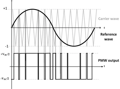
The PWM technique is the fundamental mechanism by which VSCs can modulate voltage waveforms to provide different AC voltage phase angles and magnitudes from the DC voltage input. This is achieved using a carrier waveform in conjunction with a reference waveform. Fig. 2 illustrates the PWM process for a single phase of VSC switches. When the sawtooth modulating signal rises higher than the voltage waveform reference from VSC control system, the lower switch is on and the upper switch is off, and a voltage
magnitude of -VDC/2 is produced. When the sawtooth
modulating signal drops lower than the voltage waveform
reference, a magnitude of +VDC/2 with upper switch on and
lower switch off. Upper and lower switch are operated in a complement mode which means that one switch is on and the other switch must be off.
The frequency of the carrier wave determines the switching frequency of the power electronics devices. High-order harmonics are inevitable incurred due to the VSC switching actions and these harmonics can be removed using a low-pass filter to enable a perfect sine-wave VSC voltage output. As the orders of high harmonics are predictable from the VSC switching frequency, a relatively small-sized filter device can be selectively tuned to remove the designated orders of harmonic orders (normally 1st order or 2nd order of switch
frequencies).
D. Modelling of converter performance
There are several methods of modelling a converter: the following lists some of the more common approaches [9]:
1) Detailed switching model: This is the most accurate approach to model a converter as the characteristics of the switching semiconductors are incorporated.
2) Switching function model: A more simplified approach as all the switching devices are considered to be ideal.
3) Time average model: The most simplified technique, as the effects of converter switching are replaced by an average effect (as demonstrated in the following figure). In this mode the harmonics are considered to be totally eliminated; consequently, calculation complexity is dramatically reduced.
From the perspective of power system dynamic study, the average model is sufficient to appropriately mimic the realistic VSC‟s AC fault response [10]. Therefore, in this paper, the time average model is selected to analyse of the VSC fault performance.
Reference wave Carrier wave
PMW output +1
-1
+VDC/2
-VDC/2
t
[image:2.595.305.552.96.279.2]t
[image:2.595.65.276.657.739.2]E. VSC-HDVC Modelling
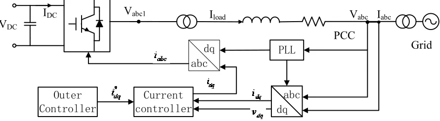
The modelling strategy for the HVDC system connecting the grid is demonstrated in Fig. 3. A VSC-HVDC control system consists of an inner current controller and out controllers. The inner current controller aims to compute VSC output voltage references in order to regulate the VSC output currents. With outer controllers, VSC output current control can be transformed into other forms of regulating P, Q, VDC or VAC, and flexible combinations for the outer
controllers can be selected to achieve various objectives. VSC grid synchronisation is not achieved naturally achieved as synchronous machines, and it must be assisted by a phase lock loop (PLL) unit. A PLL unit is used to track the voltage angular speed in a timely fashion for the Park and inversed Park transformations which facilitate the VSC control. The Park transformation converts abc three-phase voltages/currents into dq voltages/currents under a rotating reference frame that is at synchronous speed when compared to the grid frequency. Usually the currents in dq form are represented using DC values. The DC values of voltages and currents are processed by the VSC control system and then transformed back to abc three-phase values via an Inverse park transformation and then processed using the VSC‟s PWM function.
III. HVDCCONTROL SYSTEM DESIGN
A. Dual sequence control scheme
Under unbalanced voltage conditions on the grid, resulting from unsymmetrical faults and/or unbalanced loading, the desire for the HVDC VSC to produce balanced output current waveforms, non-oscillating stable P&Q outputs and to ensure DC voltage means that there is an incentive to develop a more advanced VSC control scheme which is termed “dual sequence control”. In such schemes, monitoring and controlling the negative sequence components of the three-phase output voltages and currents is incorporated with the conventional positive sequence control loops. Furthermore, the negative sequence controller enables the response of the converter to be more similar to a synchronous generator during unbalanced fault conditions [11]. The ENTSO-E grid code proposal also requires that converters should be able to
inject unbalanced current in the event of unbalanced faults [7]. It is therefore prudent to include a negative sequence controller in this model to ensure that performance during unbalanced network disturbances can be synthesised.
B. Inner current control loop
In this control loop, the three-phase voltages and currents, as measured at the point of common coupling (PCC), are transformed into dq values by one positive sequence rotating reference frame and one negative sequence frame both of which mutually rotate in opposite direction with the same fundamental frequency.
(1)
(2)
(3)
(4)
The magnitudes of id & iq is regulated by the PI controllers with the inner current control according to the reference values. To achieve the control of , the VSC output voltage
references vd & vq are computed taking account of the coupling effect of the VSC phase reactor and transformer.
When the current is controlled, the associated output voltage of the converter can then be determined. The following Fig. 4 demonstrates how the converters are connected to the grid:
PCC
Vabc1 Iabc Vabc
[image:3.595.91.536.61.184.2]HVDC Grid
Fig. 4. Converters connecting to the grid
V
abc1V
abcI
abcGrid
Outer
Controller
Current
controller
PLL
dq
abc
dq
abc
PCC
V
DCI
DCI
load [image:3.595.323.555.376.488.2]From the convention of the voltage and power variables for an AC transmission line section, it is clear that the relationship between the grid voltage, converter output voltage and current value is as follows:
(5)
Representing the above in the dq positive and negative sequence forms:
(6)
(7)
(8)
(9)
Following inverse transformation of the dq voltage components to abc voltage components, the PWM produces the required voltage waveforms to complete the final step of VSC control.
C. Outer control loop
In this loop, the reference values of and can be computed by controlling various system variables (P&Q&VDC&VAC) using the equations presented below:
Reference value of can be determined by the desired reference value of AC real power:
(10)
Or by the desired reference value of DC voltage:
(
) (11)
The reference value of can be determined by the desired reference value of AC reactive power:
(12)
Note that the voltage drop between and is
dependent on the current passing through the impedance (resistance negligible compared to the high reactance) of phase reactor and transformer as shown in Fig. 4. Therefore, in order to regulate the voltage amplitude at reference value (i.e. make the voltage amplitude at the PCC close to its
desired reference value ), the reactive power should be
controlled accordingly [4].
The output current reference are computed by
comparing the power/voltage references with the measured values:
(13)
(14)
(15)
(16)
D. Current limitation
Current limitation must be applied to protect the power electronics from thermal damage in case that an excessive current may occur (e.g. during a solid AC fault). The limitation on VSC output overcurrent is simply achieved by adding up/ down limits in the PI controllers in both outer control loop and inner current loop.
The current limitations would have a significant influence on VSC output current waveforms and provide useful information for local or system-wide protection schemes. Further work needs to be carried out to establish in more detail how the current limiting function can be designed to make the converter more “grid-friendly” (i.e. with less distorted waveforms), as well as to investigate how the information in the VSC control system can assist the performance of future power system protection schemes.
IV. SIMULATION RESULTS
In this paper, a simplified HVDC model is designed to represent a converter-interfaces source with a capacity of 1000MVA. The whole structure of the modelled system is demonstrated in Fig. 3, and its controlling system is using the control strategy described in section III. This 1000MVA HVDC link is connected to a grid considered to be an infinite bus.
A. Case study 1: demonstration of fault response of converter with positive sequence controller only
In this case study, the complete model of an HVDC station is built. The DC voltage and the PCC voltage are controlled through the outer control loop of the converter: i.e. the
reference values are determined by equations (14) and (16). The constraint of pu is set at the current controller to limit the maximum fault current.
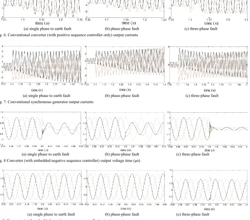
Single phase to earth, phase-phase and three-phase faults are applied to the PCC to check how the converter responds, the corresponding output of the converter is recorded in Fig. 5 and 6.
From the above graphs, it can be seen that the controller can provide a fast response when a fault is placed on the AC
system. Soon after the fault, the converter adjusts its output voltage to facilitate current control. The reaction time of
[image:5.595.59.546.82.182.2](a) single phase to earth fault (b) phase-phase fault (c) three-phase fault Fig. 5. Conventional converter (with positive sequence controller only) output voltages
(a) single phase to earth fault (b) phase-phase fault (c) three-phase fault Fig. 6. Conventional converter (with positive sequence controller only) output currents
(a) single phase to earth fault (b) phase-phase fault (c) three-phase fault Fig. 7. Conventional synchronous generator output currents
(a) single phase to earth fault (b) phase-phase fault (c) three-phase fault Fig. 8 Converter (with embedded negative sequence controller) output voltage time ( )
[image:5.595.58.548.251.682.2]converter to reach its new steady state condition is around 50ms. The output current of the converter is limited to around 1.5 pu in accordance with the limits set in the model. It is also clear that the converter is capable of providing unbalanced fault currents under unbalanced fault conditions. However, neither the response (in terms of both voltage and current) is dissimilar to a conventional synchronous machine output under such fault conditions. Finally, the reactive power injection during the fault from the converter is zero, and therefore the reactive current injection is obviously also zero. This is not in accordance with the requirement of the grid code, therefore further upgrading of the controller (development of fault detection algorithm) should be done to satisfy the grid code.
B. Case study 2: demonstration of the performance of dual sequence converter control scheme
In this case study, the operation of the negative sequence controller in parallel with the positive sequence controller is investigated. The HVDC model is identical to that used in case study 1, while the output reference values of the
positive and negative sequence controllers are fixed initially:
= 0.8 pu, =
0 pu. The function of this control
system is to ensure that the output current of the converter is fixed at 0. 8 pu under all conditions.
Single phase to earth, phase-phase and three-phase faults are applied to the PCC to investigate the converter response. The corresponding outputs of the converter are displayed in Fig. 8 and 9.
It is evident that this new controller is an improvement over the previous control scheme shown in case study 1. Under different fault condition, the converter can adjust its output voltage quickly to control the output current. The output current is strictly constrained to its reference value and the output voltage can be used to clearly imply the type of the fault. However, under this control scheme, traditional overcurrent protection systems would not be suitable for protection at the converter terminals.
In this session a simple test of the dual sequence controller is performed and it is very satisfactory.
V. CONCLUSION
Concerns about protection challenges are arising due to the increasing introduction of converter based energy sources. To fully understand the challenge, the detailed characteristics of the converters were researched and displayed. Initial models of the VSC-converter were built and tested. With the help of the modelling results, it can be seen that the concerns about the converter dominated power system protection performances are valid. The next step should be upgrading the model into more realistic level. Then further studies would be done to check how the behavior of the power system and its associated protection system can be affected by increasing the penetration level of the converter sources as future energy scenarios would be reflected. Ultimately, viable
solutions will be sought to overcome any identified limitations of the existing protection approaches.
REFERENCES
[1] “Network Code on Requirements for Grid Connection applicable to all Generators.” ENTSO-E, Mar-2013. Retrieved Jan, 2014, Available at:
http://networkcodes.entsoe.eu/wp-content/uploads/2013/08/130308_Final_Version_NC_RfG1.pdf [2] “UK Future Energy Scenarios 2013.” National Grid, 2013. Retrieved
Dec, 2013, Available at: http://www2.nationalgrid.com/uk/industry-information/future-of-energy/future-energy-scenarios/
[3] “Electricity Ten Year Statement 2013.” National Grid, 2013. Retrieved Feb, 2014, Available at: http://www2.nationalgrid.com/UK/Industry- information/Future-of-Energy/Electricity-ten-year-statement/Current-statemen
[4] J. Zhu, C. D. Booth, G. P. Adam, A. J. Roscoe, and C. G. Bright, “Inertia Emulation Control Strategy for VSC-HVDC Transmission Systems,” IEEE Trans. Power Syst., vol. 28, no. 2, pp. 1277–1287, May 2013.
[5] C. A. Plet, M. Graovac, T. C. Green, and R. Iravani, “Fault response of grid-connected inverter dominated networks,” in 2010 IEEE Power and Energy Society General Meeting, 2010, pp. 1–8.
[6] K. J and K. B, “Understanding Fault Characteristics of Inverter-Based Distributed Energy Resources,” National Renewable Energy Laboratory (NREL), NREL/TP-550-46698, 2010.
[7] “Network Code on HVDC Connections,” ENTSO-E, 30-Apr-2014. Retrieved Apr, 2014, Available at:https://www.entsoe.eu/major-projects/network-code-development/high-voltage-direct-current/ [8] “The Grid Code.” National Grid, 31-Mar-2014. Retrieved Apr, 2014,
Available at: http://www2.nationalgrid.com/UK/Industry-information/Electricity-codes/Grid-code/The-Grid-code/
[9] D. G. P. Adam, voltage source converter: modulation, control and applications in power systems. CreateSpace Independent Publishing Platform, 2013.
[10] T. Wijnhoven, J. Tant, and G. Deconinck, “Inverter modelling techniques for protection studies,” in 2012 3rd IEEE International Symposium on Power Electronics for Distributed Generation Systems (PEDG), 2012, pp. 187–194.