Channel Estimation and Tracking for Closed Loop
EO-STBC with Differentially Encoding Feedback
Mohamed Nuri Russin and Stephan Weiss Center for Excellence in Signal & Image Processing
Department of EEE, University of Strathclyde ,Glasgow, Scotland, UK {mohamed.hussin,stephan. weiss}@eee.strath.ac.uk
Abstract-Extended orthogonal space time block coding (EO STBC) can achieve high transmit diversity over a multiple input mUltiple-output (MIMO) channel. To do so, it requires channel state information on the transmitter side, which needs to be estimated and fed back from the receiver. T herefore, this paper explores an estimation and tracking scheme by means of a Kalman filter, which is integrated with EO-STBC detection and exploits the smooth evolution of the channel coefficients by applying differential feedback. For slow fading, we propose the inclusion of a drift vector in the Kalman model, which is motivated by a second order approximation of the underlying channel model and can be shown to offer advantages in terms of temporal smoothness when addressing channels whose coefficient trajectories evolve smoothly.
I. INTRODUCTION
Amongst various space-time block coding (STBC) schemes [1], [2], orthogonal STBC (O-STBC) has low decoding complexity and can achieve full diversity gain at a code rate equal to one. However, for complex constellation and more than two transmit antennas, the code rate must be relaxed in order to admit full diversity. In contrast, quasi-orthogonal STBC (QO-STBC) using four transmit antennas achieves full code rate at the expense of a loss in diversity gain [3]. Constellation rotation was proposed for QO-STBC in order to mitigate symbols interference to attain full code rate and full diversity [4] at the cost of an increase in system complexity.
Extended O-STBC (EO-STBC) inherits O-STBC's low de coding complexity [5], but at a code rate of one, and full diversity gain plus an additionally array gain. The latter is realised by appropriate beamsteering, which depends on the channel estimate and needs to be fed back in a closed-loop architecture from the receiver to the transmitter.
The EO-STBC scheme in [6] has investigated quantised feedback of optimum parameters. When operated in a fading scenario, the channel coeff cients are slowly time-varying due to small Doppler spread and large coherence times [7]. This smooth evolution of channel coeff cients has motivated the investigation of differential feedback in [8], which shows that improved performance to standard quantisation is possible at half the feedback bandwidth over a range of realistic Doppler spreads.
EO-STBC requires accurate knowledge of channel state infonnation (CSI) both at the transmitter for beam steering, as well as at the receiver for decoding [9]. Channel estimation
is therefore crucial, and can only be avoided through the use of STBC based on differential or double differential modulation [10], [11]. This alleviated the need for CSI, but requires the channel to remain stationary for a few successive symbol periods and incurs a performance degradation by 3dB and 6dB, respectively, compared to coherent modulation [lO], [11 ].
In order to obtain CSI, joint channel tracking and symbol detection schemes have been proposed, such as the decision directed (DD) approach in [12] for O-STBC. In order to link the decoding stage with the tracking stage, a Kalman f Iter was adopted in [12], which can be effectively based on an auto regressive (AR) state-space model of order p (AR-p) for the time-varying channel. For example, an AR-l model has been used in [13]. In order to allow a better prediction, particularly for slow-fading scenarios and in light of the fact that for STBC the channel has to be predicted ahead over two symbol periods, an AR-2 model has recently been proposed in [14].
In this paper, we extend the work in [8] by proposing a channel estimation and tracking scheme based on an AR-2 model-based Kalman f lter. This system needs to be adapted in order to interlink with the EO-STBC symbol detection in the Kalman f lter's correction step. Therefore, Sec. II provides a brief overview over EO-STBC with differential feedback. In Sec. III, channel estimation and tracking by means of a Kalman f Iter is introduced. Results are presented in Sec. IV, and Sec. V provides a summary and conclusions.
In our notation, lower and upper-case case bold face vari ables such as hand H represent vector and matrix quantities, respectively. For a matrix H, the transpose is denoted by HT, the Hermitian by HH, and the complex conjugate by H*. The statistical expectation operator is given by
[{.}.
II. SYSTEM MODEL
A. Cl osed Loop EO-STBC
In this section we consider a model for a time-varying multiple input single output (MISO) system. Based on EO STBC transmission as outlined in Fig. 1, the forward link has four transmit antennas and a single receive antenna. The feedback link is required to return information on the steering angles 191 and 192, with which the f rst and third antenna signal are modif ed. We will later see that by judiciously selecting these angles based on knowledge of the channel at the receiver, the combined diversity and array gain of the
Tx MISO channel Rx
,--- :>-'<YiI
s
d
n]
eJ 1 hu v
[
n]
Sn CO E-<
- CFJ
s3
[
n]
6
;0>."-l
�2
s4
[
n]
h�
!,Oi
rl
I
deco:
er
---�
Figure 1. EO-STBC system with channel estimation and tracking in the receiver to aid symbol detection and estimation of the optimum beamsteering angles 191 and 192, which are differentially encoded and returned to the transmitter.
system can be maximised. For simplicity, we assume below that the feedback channel is error free with no latency. Below, the system components in Fig. 1 are reviewed.
1)
Transmit Signal and Channel: The channel is time varying with a normalised angular Doppler frequency r2D =wDTs, with Ts being the symbol rate. Due to mobility and multipath propagation, the carrier frequency will experience Doppler spread. For slow fading channels, each channel coef f cient evolves smoothly over time. The received signal r[n] is characterised by
r[n] = h�Ansn + v[n] (1)
where Sn is the transmit data vector, An is a unitary diagonal matrix, and v[n] is zero mean uncorrelated complex Gaussian noise with variance
0-;.
The vector hn E <[4,hn = [hl,n ... h4,n]T
contains spatially independent and identically distributed wide sense stationary (WSS) Ray leigh fading channel coeff cients. The spatio-temporal covariance matrix of these coeff cients is therefore given by
(2)
where
JoC)
is the zeroth order Bessel function of f rst kind [7], ando-�
the variance of the Rayleigh distributed channel coeff cients. With EO-STBC encoding over two successive time slots, the selection of the transmit vector is given by_
{
i
[s[n], s[n], s[n + 1], s[n + I]]T ,Sn
--:d
-s* [n], -s* [n], s* [n - 1], s* [n - I]]TThe diagonal beamsteering matrix An
n even
n odd.
(3)
A n = diarr b
{
ej,J'l[n] 1 ej,J'2[n] I" ,}
(4)effectively rotates the channel taps hI [n] and h3 [n]. Since An is unitary, it has no effect on the transmitted power.
The feedback angles JI [n] and J2 [n] can be absorbed into the estimated channel. Let the estimated channel with
incorporated angles can be given by
hn = Anhn (5)
where hn is the true transmission channel. At the receiver side, the parameters JI and J2 are extracted from the estimated channel coeff cients. Therefore a simple correction
(6)
can extract the true channel coeff cients from the estimate incorporating the known beamsteering angles.
2)
Received Signal: As in a standard STBC system, the receiver gathers two subsequent samples in a vector rn such that[
r[n]]
r*[n + 1] (7)
based on the equivalent transmit vector Sn = [s[n], s[n + I]]T,
equivalent noise vector v n = [v [n], v* [n + 1]] T, and the space
time equivalent transmission channel matrix Hn. The latter can be formulated as
H -n -
[
hn[n] h21[n + 1] (8)The components of Hn are a mixture of channel coeff cients and rotations due to beamsteering with
hn[n] ej,J,[n] hI [n] + h2 [n] (9)
hI2[n] ej,J2[n]h3[n] + h4[n] (10)
h21[n+l] e-j,J2[n+I]h;[n+l] + h:[n+l] (11)
h22[n+l] -e-j,J,[n+I]h�[n+l]- h;[n+l]. (12)
3) Signal Detection: Detection is performed over a block duration consisting of two successive symbols periods. The decision statistic vector sn = [s[n], s*[n+l]]T can be obtained
via linear combination with space-time equivalent estimated channel matrix Hn as
(13)
where v n =
H;;
v n is the noise after decoding. Let thematrix Gn =
H
H nHn, which can be decomposed into [image:2.612.153.464.52.226.2]Gn = HH nHn + (t.Hn)HHn. The matrix t.Hn represents
the error due to both estimation and time variation, which creates inter-symbol interference in the detection process and increases the noise f oor. In the absence of estimation errors, i.e. Hn = Hn, any errors are only due to time-variations and
the elements of Gn become
with
gl1[n]
G -n -
[
gl1[n] g21[n]2 4
2::
Ihm[nW +2::
Ihm[n + lWm=1 m=3
+)R{ ej{ldn] hI [n]h;[n]
(14)
+ ej{l2[n+l]h3[n + l]h:[n + I]} (15)
ej({l2[n]-{ldn]) hi [n]h3[n]
_ej({l2[n+l]-{ldn+l])hi[n + l]hdn + 1] +e-j{ldn]hi [n]h4 [n]
-e-j{ldn+1]hi[n + l]h4[n + 1] +ej{l2[n]h;[n]h3[n]
_ej{l2[n+l]h;[n + l]h3[n + 1] (16)
+h; [n]h4 [n] - h;[n + l]h4[n + 1] (17)
gi2[n]
2 4
2::
Ihm[n + lW +2::
Ihm[nWIII. CHANNEL ESTIMATION AND TRACKING
The EO-STBC receiver requires the knowledge of the channel coeff cients both for detecting symbols as well as for computing the optimum phase angles tJi,n, i = {1, 2}, to be
used for beamsteering. Therefore, below an approach to track the channel coeff cients is presented, which is initialised and interleaved with channel estimation steps.
A. Channel Estimation
An initial channel estimate for the MISO system hn can be obtained by transmitting a training sequence over
L
symbols. If this transmit data is assembled in a data matrix Sn E CLX4 and transmitted without beam steering, the minimum mean square error (MMSE) solution for hn forL 2: 4
can be calculated as(23)
where rn E CL is the vector of received samples, and "in is the SNR at the receiver. The formulation in (23) includes the ZF estimate with the case "in ----+ 00.
For
L
=2,
SH n = [sn Sn+l] E C2X4 with Sn def ned in (3)is the orthogonal data matrix. The MMSE solution requires the left pseudo-inverse [15], and due to orthogonality of Sn
simplif es to
A "in
H
-hMMSE = --S nrn (24)
1 + "in
m=1 m=3
+)R{ej{ldn+l]h1[n + l]h;[n + 1] + ej{l2[n+l]h3[n + l]h:[n + I]}
Either (23) or (24) can be used to initialise the subsequent Kalman tracking, and can also be employed to re-initialise the (18) tracking system in periodic intervals.
The maximisation of the received gain is coupled to the maximisation of the on-diagonal elements of Gn, which is achieved by setting
191 [n] tJ1[n+l] tJ2[n] tJ2[n+l]
-L {hI [n]h; [n]}
-L{h1[n + l]h;[n + I]} -L{h3[n]h:[n]}
-L{h3[n + l]h:[n + I]}
(19) (20) (21) (22)
However, unlike in the stationary case [6], the off-diagonal elements gI2[n] and g21[n] are now f nite and create inter symbol interference in the process of detecting s[n] and s[n +
1].
B. Differential Quantised Feedback
For many wireless applications, the maximum Doppler shift 0,D can be considered small. This leads to a smooth evolution of channel coeff cients, which enables differentially encoding single bit feedback over a realistic range of maximum Doppler shifts 0,D [8]. Differentially quantised feedback requires opti misation of the quantiser step size IL, which causes a trade-off between slope overload due to too slow tracking for small values of IL, and too coarse quantisation for larger values of IL that causes poor performance irrespective of the rate of change. Below, we will aim to construct channel estimation and tracking that can work together with the differential feedback previously explored in [8].
B. Kal man-Based Tracking & Detection
The Kalman f lter approach has been utilised widely for channel tracking. Here, we select a simple AR-2 model which contains a so called drift vector ahn in order to better exploit the smooth evolution of the channel coeff cients as compared to the standard AR-I model utilised in most publications. An accurate system can be built from a prediction model exploiting the temporal correlation expressed in (2) [7], while here a simplif ed heuristic state-space model
is invoked, containing Wn as the drift error with variance
(J�,
is the only parameter which can be tuned to control the drift of ahn.This state-space model is incorporated in the Kalman f lter algorithm outlined in Tab. I, where an a-priori estimate ob tained in a prediction step is improved based on the detected symbols contained in a data vector Sn, yielding the a-posteriori estimate hnln of the channel as in Fig. 1.
C. Decision-Directed Channel Tracking
The Kalman f Iter algorithm in Tab. I is updated at every symbol period based on the detected data. In this section, we want to customise the Kalman f1ter algorithm to take the EO STBC setup as depicted in Fig.I into account. While Tab. I
Table I
KALMAN FILTER TO ITERATIVELY ESTIMATE AND TRACK
hnln.
[Input]
r[n]
={
q[n]
r2[n+l].
Sn
={
t
[s[n], s[n], s[n + 1], s[n + lW
"2
[s* [n], s* [n], s* [n - 1], s* [n - lW
_
[
AnSn
Sn
= 04Xl[Initialisation]
A
=[
14x4 04x4
Q =
[
04X4 04X4
POlO
= {Isxs}[Iteration]
14x4 14x4 04X4 0"�I4x4
hnln-1
=Ahn-lln-l
Pnln-1
=APn_lln_lAH
+
QPnln
= (Isxs -Knsn)Pnln-l
hnln
=hnln-1 +Kn.
[
r[n]-
[h;ln_lSn]
]
[Output]
n
evenn
odd.already assumes that Sn has been suitably detected, below
we formalise the decision directed approach in [12] for the purpose of our proposed architecture. Thereby, two a-priori estimates are performed to predict the time-varying channel vectors during the current EO-STBC block. Thereafter, both a-priori estimates are updated according to the algorithm in Tab. II.
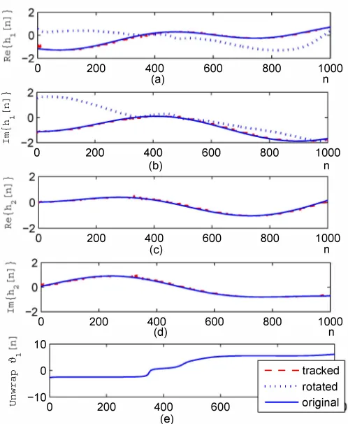
D. Impact of Beamsteering on Channel Estimation
According to Fig.l, the feedback angles 191[n] and 192[n] are absorbed into the original channels of antennas one and three. Fig 2 shows the channel variations when r2D =
0.0037f.
Fig. 2(a)-(d) show real and imaginary parts of the trajectory of the true channel coeff cients hd n], i =
{1, 2}
and, in case ofh1[n], real and imaginary part of the trajectory of the modif ed coeff cient (dashed curves) in Fig. 2 (a)-(b).
The trajectory of the feedback angle 191 [n] is shown in Fig. 2( e). In order to avoid divergence of the Kalman f Iter, a re-initialisation with an MMSE estimate driven by pilot symbols is performed every K symbols, with the default value set to K =
12.
This is necessary, since e.g. a coeff cienttrajectory passing close to the origin leads to rapidly changing angles, and therefore a higher degree of non-stationarity. Particularly Fig. 2(a)-(b) very clearly show how beamsteering angles affect the rate of change in terms of the coeff cients.
Table II
KALMAN-BASED CHANNEL OPERATION WITH DECISION-DIRECTED UPDATING OVER TWO SUCCESSIVE SYMBOL PERIODS.
[Initialisation]
Initial channel estimate, transmitting without beamsteering.
[Tracking]
Channel tracking, transmitting with beamsteering.
[Prediction]
Kalman update to obtain a poriori estimates
hnln-1
=Ahn-lln-l
andhn+lln-l
=AAhn-lln-l
Compute feedback steering angles for detecting feedback symbols
[tJdnln - 1], J2 [nln - III and [tJdn + lin - 1], J2[n + lin - III
as in (20) and (22).Construct priori EO-STBC matrix
Hnln-1
with absorbed feedback angles as in (8)Obtain coarse symbol estimate as
[sC[nln - 1], se[n + lin - IllT
=H�n_l
[r[n], r* [n + IllT
[Filtering]
Kalman correction to obtain a posteriori estimates without effect of beamsteering for
hnln
andhn+lln+l
as in Tab. I.Compute feedback steering angles for detecting and for beamsteering
[tJdnln], t92[nlnll and
[tJ1[n + lin + 1], t92[n + lin + 1]] as
in (20) and (22).Construct postriori EO-STBC matrix
Hnln
with absorbed feedback angles as in (8).Detect symbols as [s[nln], s[n + IlnllT =
H�n
[r[n], r* [n + I]V
Although the problem occurs in channel hI [n] due to the beamsteering, the impact is felt across all channel coeff cients.
IV. SIMULATIONS AND RESULTS
In the following, the BER performance of EO-STBC with differential feedback and Kalman-based channel tracking is explored. The channel tracking is initialised, and interleaved every K =
{12, 24}
symbol periods a transmission of twopilot symbols and an MMSE channel estimate to re-initialised the Kalman tracking algorithm, incurring
8%
, and4%
loss in bandwidth eff ciency, respectively. Below, we compare the results for the simplif ed AR-2 model with the standard AR-l Kalman f1ter. Simulations are performed over an ensemble of104
randomised channel realisations with a maximum Doppler spread r2D ={0.0037f, 0.0057f, O.Oh}.
BER curves for a transmission system with a maximum Doppler spread r2D =
0.0037f
are shown in Fig. 3. Fordifferent update periods K, the AR-2 Kalman f Iter with solid BER curves has a small advantage over the AR-l Kalman
�"
J
o"
�
200 400"
"
600:
",
800:
,
==:J
1000�) n
;"
-:
�
':
";;::
"�
o 200 400 600 800 1 000
200
(b)
400
(c)
600 800
n
1000
n
L:
F
:
S
-
---i
o 200 400 600
10
<P .... p< 0 ro
�
§ -10
0
(d)
200 400 600
(e)
800
-1000
n J
-tracked
, , , , , " rotated
---original
Figure 2. Coel'f cient evolution of channel coefi" cients - channel one with (a) real and (b) imaginary part, channel two with (c) real and (d) imaginary part, and (e) evolution of the angle returned to the transmitter via feedback.
� w
'"
, , , , , " Known chs.(benchmark) , -iii-' AR 1 (tracking 24 symbols)
, -Q-' AR 1 (tracking 12 symbols) ::.
10-7L-________ -L ________ � __________ � ________ �
o 5 10
SNR
15 20
Figure 3. BER performance of EO-STBC system with channel estimation and tracking based on an AR-I (dashed) and AR-2 (solid) Kalman f1ter for channel variations with iJv = O.0031f.
Bit Error Rate
10
[image:5.612.322.547.56.239.2] [image:5.612.48.297.83.386.2] [image:5.612.325.547.308.488.2] [image:5.612.62.286.499.680.2]10-4 •••••••••••••••••••••••••••••••••••••••
... AR 2 (tracking 12 symbols) : _ AR 2 (tracking 24 symbols)
10-5• " " '" Known chs.(benchmark)
, -iii-' AR 1 (tracking 24 symbols)
,-Q-, AR 1 (tracking 12 symbols) :
10-6 L--=:======::::j:======:::;:::� ___ L-___ �
o 5 10
SNR
15 20
Figure 4. BER performance of EO-STBC system with channel estimation and tracking based on an AR-I (dashed) and AR-2 (solid) Kalman f1ter for channel variations with iJv = O.0051f.
� w
'"
10
Bit Error Rate
, , , , , " Known chs.(benchmark) , -111- , AR 1 (tracking 24 symbols)
, -Q-' AR 1 (tracking 12 symbols)
10-5L-________ -L ________ � __________ � ________ �
o 5 10
SNR
15 20
Figure 5. BER performance of EO-STBC system with channel estimation and tracking based on an AR-I (dashed) and AR-2 (solid) Kalman f1ter for channel variations with iJv = O.011f.
approach. Particularly at high SNR, a signif cant advantage for the AR-2 system can be noted. The dashed line belongs to a genie aided system with perfect knowledge of CSI at both transmitter and receiver.
Fig.4 shows the same BER performance for a higher max imum Doppler spread 0,D =
0.0051r.
The performance of theAR-2 Kalman f lter (solid curves) still outperforms the AR-l model (dashed curves), but the higher rate of channel variation has reduced the benef t compared the results shown in Fig. 3 for the lower variation.
Finally, a maximum Doppler spread of 0,D =
O.Ob
leadsto the performance characterised in Fig. 5. The performances of both AR-l and AR-2 are very similar, with a negligible advantage for the AR-2 model, which provide little benef t in a faster time-varying channel.
V. CONCLUSIONS
In this paper, we have considered EO-STBC with beam steering in order to maximise the joint diversity and array gain of such a MIMO transceiver. EO-STBC requires feedback of the steering angles, which can be calculated from channel estimates at the receiver. Since the channel requires to be estimated in order to decode the EO-STBC signals with maximum benef t, we have discussed a Kalman estimator to track the channel coeff cients. Their smooth variation has previously motivated a differentially encoded feedback of steering angles [8], and here additionally set the incentive to replace the AR-I state-space model of the basic Kalman channel estimator with an AR-2 model that is capable of imposing additional smoothness.
Simulation results have shown that the overall EO-STBC system achieves suitable BER values, and that the performance of the proposed system offers a distinct advantage for lower Doppler spreads and the inclusion of an AR-2 model instead of an AR-l model.
For the f nal paper, we are aiming to generate more de tailed results, and analyse the system w.r.t. achievable BER performances for the case of errors only due to the temporal variation of the system.
REFERENCES
[1] S. M. Alamouti, "A Simple Transmit Diversity Technique for Wireless Communications," IEEE Journal on Selected Areas in Communications, vol. 16, pp. 1451-1458, Oct. 1998. [2] V. Tarokh, H. Jafarkhani, and A. Calderbank, "Space-time
block codes from orthogonal designs," IEEE Transactions on Information Theory, vol. 45, pp. 1456-1467, July 1999. [3] H. Jafarkhani, "A quasi-orthogonal space-time block code,"
IEEE Transactions on Communications, vol. 49, pp. 1-4, Jan uary 2001.
[4] C. Yuen, Y. L. Guan, and T. T. Tjhung, "Full-rate full-diversity STBC with constellation rotation," in 57th IEEE Semiannual Vehicular Technology Conference, Spring, vol. 1, (Jeju, Korea), pp. 296-300, April 2003.
[5] M. Celebi, S. Sahin, and U. Aygolu, "Full rate full diversity space-time block code selection for more than two transmit antennas," IEEE Transactions on Wireless Communications,
vol. 6, pp. 16-19, January 2007.
[6] N. E. Eltayeb, Space-Time Coding for Broadband Point-to Point and Collaborative Wireless Communications. PhD thesis, Loughborough University, January 2009.
[7] K. Baddour and N. Beaulieu, "Autoregressive modeling for fading channel simulation," IEEE Transactions on Wireless Communications, vol. 4, pp. 1650-1662, July 2005.
[8] M. N. Hussin and S. Weiss, "Extended orthogonal space-time block coded transmission with quantised differential feedback,"
in 7th International Symposium on Wireless Communication
Systems, pp. 179-183, September 2010.
[9] C. Budianu and L. Tong, "Channel estimation for space-time or thogonal block codes," IEEE Transactions on Signal ProceSSing,
vol. 50, pp. 2515-2528, October 2002.
[10] B. Hughes, "Differential space-time modulation," IEEE Trans
actions on Information Theory, vol. 46, pp. 2567-2578, Novem
ber 2000.
[11] Z. Liu, G. B. Giannakis, and B. L. Hughes, "Double differential space-time block coding for time-selective fading channels,"
IEEE Transactions on Communications, vol. 49, pp. 1529-1539,
September 200 I .
[12] Z. Liu, X. Ma, and G . B . Giannakis, "Space-time coding and Kalman f ltering for time-selective fading channels," IEEE
Transactions on Communications, vol. 50, pp. 183-186, Febru
ary 2002.
[13] S. Haykin, K. Huber, and Z. Chen, "Bayesian sequential state estimation for MIMO wireless communications," Proceedings of the IEEE, vol. 92, pp. 439-454, March 2004.
[14] L. Ros, H. Hijazi, and E. P. Simon, "Paths complex gain tracking algorithms for OFDM receiver in slowly-varying channels," in
4th International Symposium on Communications, Control and Signal ProceSSing, (Cyprus), pp. 1-6, March 2010.
[15] G. H. Golub and C. F. Van Loan, Matrix Computations. Balti more, Maryland: John Hopkins University Press, 3rd ed., 1996.