Multibody Dynamics for
Biologically Inspired Smart Space Structure
Thomas Sinn1 and Massimiliano Vasile2
Advanced Space Concepts Laboratory, University of Strathclyde, Glasgow, United Kingdom
Structures in space are often just serving a single purpose. By developing a structure which is able to change it properties and adapt to changing environmental conditions, the costs of space missions can be decreased significantly. The design and simulation of such a structure is presented in this paper. The developed structure consists of an array of interconnected cells which are each able to alter their volume due to internal pressure change. By coordinated cell actuation in a specific pattern, the global structure can be deformed to obtain a desired shape. A multibody code was developed which constantly solves the equation of motion with inputs from internal actuation and external perturbation forces. During the inflation and actuation of the structure, the entities of the mass matrix and the stiffness matrix are changed due to changing properties of the cells within the array based on their state and displacement. This paper outlines the principles behind the developed code and gives examples in two dimensional and three dimensional space.
Nomenclature
A = Cross-section Area of Cells ANN = Artificial Neural Network D = Damping Matrix
E = Modulus of Elasticity of Cell Fact = Actuation Forces
Fext = External, Perturbating Forces
Finf = Inflation Forces
G = Shear Modulus
I = Moment of Inertia J = Torsion Inertia Moment K = Stiffness Matrix L = Length of Cell
M = Mass Matrix
PID = Proportional-Integral-Derivative (controller) SAM = Self-inflating Adaptive Membrane
SRP = Solar Radiation Pressure = Position Vector
= Velocity Vector
= Acceleration Vector
ONTINIOUS space exploration requires ever increasing size and functionality of space structures to fulfill the ever increasing user demands. Especially large deployable space structures are needed in a variety of fields ranging from satellite antennas1 and reflectors over solar sails to habitat modules for extraterrestrial exploration. Nowadays, most space structures serve just a single purpose making especially large space structures very expensive due to their high storage volume and mass. Furthermore, on ground testing validating the spacecrafts accuracy and functionality in the space environment are very costly2. A solution would be the development of a spacecraft or space structure capable of changing its shape in space. This adaption capability would make on ground accuracy
1
PhD-Candidate, MSc., Advanced Space Concepts Laboratory, University of Strathclyde, 75 Montrose Street, G1 1XJ, Glasgow, UK, AIAA Student Member, [email protected]
2 Professor, Advanced Space Concepts Laboratory, University of Strathclyde, 75 Montrose Street, G1 1XJ,
Glasgow, UK, AIAA Senior Member, [email protected]
2
testing unnecessary since the structure could adapt its shape to account for shape changes introduced by the space environment3. An example would be a space telescope that could adapt its optic in space to account for unpredictable thermal expansion in order to increase its accuracy. Further application are envisioned in the field of solar sails where the morphing structure can replace the entire altitude control system by changing the solar sail surface area subjected to the solar wind. Also space based solar power satellites are in need of shape changing structures in order to direct the sunlight via a shape changing concentrator on a geostationary platform while the Earth rotates and orbits around the Sun.
New simulation tools need to be developed for these morphing space structures, with every tool customized for one kind of adaptive structure. The development of these tools is important to properly design these smart space structures in order to maximize their functionality in space. Smaller bench test models of these ultra lightweight smart structures can be tested on ground but as soon as these structures become bigger, simulations become necessary to predict the performance in space without the gravitational pull here on Earth.
I.
Design Idea
The developed design makes use of a bioinspired concept that employs the same principle than a plant capable of moving its flower head towards the direction of the sun, which is known as heliotropism4. By changing the turgor pressure between adjacent cells in the plant’s stem, called motor cells, the stem of the plant flexes. Past research at the University of Strathclyde has led to the development and inflation simulation of the Self-inflating Adaptive Membrane (SAM)5.
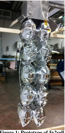
The smallest reoccurring elements in this design are single cells which are capable of changing their volume due to inflation. The first option to manufactured the cells is to use flat circular thin Mylar sheets which are welded together on their circumference forming ellipsoids once they are inflated. An array of 5x2x1 (x,y,z direction) Mylar cells can be seen in Figure 1. The second option is to fabricate these inflatable cells with a hyperelastic material like latex or silicon rubber which is capable of expanding its surface area due to internal pressure change. The second option performs in a more similar matter then the motor cells of the plant which are capable of increasing their volume once the internal turgor pressure changes.
To inflate the adaptive structure the passive system of residual air inflation is used6. The principle makes use of the expansion of trapped gas by decreasing the environmental pressure. By manufacturing a highly flexible structure with the enclosed trapped air at sea level condition and then subjecting it to the vacuum of space, the structure will inflate itself.
The shape of the overall structure can be altered by coordinated volume change of single cells in the multiple cell array. As described above this volume change is undertaken by a pressure increase due to air molecule increase. Two methods of this pressure increase have been evaluated in previous work. One option would be the use of micropumps inbetween two cells to transfer air molecules inbetween them, therefore always one cell would be inflating and the other deflating. Another option is the use of valves between all the cells with a central pressure source7. The system of valves would transfer the airmass to the cell which needed to be actuated. Multiple colonies of cells with a central pressure source could be added together to a larger structure with redundent and
exchangable systems. Each method has its pros and cons and the use of one over the other needs to be evaluated for each proposed application and mission.
II.
Adaptability and Control
[image:2.612.411.538.312.572.2]In order to obtain a desired global shape, the local shape change capabilities of the numerous actuator cells needs to be controlled. Due to the micro gravity and the vacuum of space, the cells itself only need internal pressures of a few hundred Pascal to be able to form a stable semi rigid structure. On ground bench test proved the functionality of concept on arrays of 5x5x2 cells but larger structures of multiple hundred of cells can only be analyzed by using simulation.
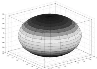
The shape of each cell can be arbitrary and is mostly dictated by the available manufacturing processes, materials and tools. For the simulation it was therefore decided to model the cells as rectangles in 2D and as cubes in 3D. The whole structure is discretized as a damper-spring system in which every cell forms the centre of a rectangle or cube with its edges made of springs and dampers. Each corner, from now on referred to as a node, is a point mass which corresponds to a fraction of the mass of the adjacent cells. Each cell is discretized with 4 beams elements in 2D and 12 beam elements in 3D as can be seen in Figure 2. Every beam element is able to transfer tension, compression, bending and torsion loads between the nodes.
Every array has (cells in x-direction + 1)*(cells in y-direction + 1)*(cells in z-direction + 1) nodes resulting in a total of 108 nodes for example for a 5x5x5 cell array.
Multibody dynamics are used to simulate the behavior of the cellular array and its responds to changing environment conditions. The equation of motion is written with mass matrix (M), damping matrix (D) and stiffness matrix (K). A structure like this has to be modeled as a dynamic system due to all the deformation and secondary stresses as a result of specific actuation patterns.
(1)
The equation of motion in Equation 1 is continuously solved in the time domain to obtain the displacement and the velocity . The input variable is the changing force within the cells and the external forces perturbating the structure. The actuation forces are the internal inflation force Finf and actuation force Fact as well as all the external
forces summarized by Fext. The application area of the forces varies depending on their origin which will be
described later in the paper.
A. Mass-, Stiffness- and Damping matrix
Mass matrix
The mass matrix is a diagonal matrix with nodes x6 rows and columns (x3 for 2D). Every node in the model is a point mass made up from the sum of the mass fractions of the surrounding cells. For example if an array consists of two by two cells with eight nodes each and with the mass of one unit, then the nodes on the corners will have a mass of unit, the nodes in the middle of the outside edge would have ¼ unit and the node in the centre would have ½ mass units. During inflation and actuation of the structure, the entities of the mass matrix change due to shifting of air molecules between the cells.
Stiffness matrix
The developed structure takes most of its shape changing potential from the coupling between in plane actuation and resulting out of plane deformation. The use of simple tension/compression springs in the stiffness matrix does not lead to the desired result. For this reason, discretization methods commonly used for finite element modeling were used to build up a suitable stiffness matrix. The use of torsion-bending beams with their coupling terms gives the stiffness matrix and therefore the developed model the capability for out of plane deformations.
In the following the 2D and the 3D case will be outlined more in detail. The two dimensional case can be used to acquire a first idea about the deformation potential of a structure without time and computational expensive simulations. An example for this could be a parabolic antenna which can be modeled in 2D to investigate the achievable curvature; 3D simulations can then be used to accurately validate the quality of the curvature with all its potential wrinkles.
Two Dimensional (2D)
[image:3.612.85.254.88.209.2]Equation 2 shows the unrotated stiffness matrix of one bending beam element in 2D. Every element of the structure has its own entity of modulus of elasticity E, crosssection area A, length l and moment of inertia I. At the beginning of the simulation these entities can be the same but they will change during the various actuation cycles.
4
3 2 3 2
2 2
11 12
3 2 3 2
2 2
0 0 0 0
12 6 12 6
0 0
6 4 6 2
0 0 (0) (0)
(0)
0 0 0 0
12 6 12 6
0 0
6 2 6 4
0 0 element element element eleme EA EA l l
EI EI EI EI
l l l l
EI EI EI EI
K K
l l l l
K
K
EA EA
l l
EI EI EI EI
l l l l
EI EI EI EI
l l l l
'
12(0) 22(0)
nt Kelement
For the 2D case, the actuator elements were connected in a line hanging from a plate (similar to the bench test model in Figure 1). The 0deg beams are aligned parallel to the mounting plate and the 90deg beam perpendicular to it. The full stiffness matrix for a six cell structure can be seen below in Equation 3.
1 11 1 11 1 12 1 12
'
1 12 1 22 2 11 2 12
'
1 12 1 22 2 11 3 11 2 12 3 12
' '
2 12 2 12 2 22 2 22 4 11 4 12
3 1
(0) (90) (0) (90) 0 0 0
(0) (0) (90) 0 (90) 0 0
(90) 0 (90) (0) (90) (0) (90) 0
0 (90) (0) (90) (0) (90) 0 (90)
0 0
K K K K
K K K K
K K K K K K
K
K K K K K K
K '
2 3 11 3 22 2 12
' '
4 12 3 12 3 22 4 22
(90) 0 (0) (90) (0)
0 0 0 (90) (0) (0) (90)
K K K
K K K K
Three Dimensional (3D)
In order to model a structure in space more accurately, the model has to be three dimensional. The beam element chosen for the 3D discretization is capable of three translatoric movements and three rotational movements at each connection point. The 2D element stiffness matrix in Equation 2 is expanded with the moment of inertia in two directions Iy and Iz as well as the shear modulus G and the torsion moment of area J. The element stiffness matrix of
an unrotated x-axis element can be seen in Equation 4.
Similar rules in global stiffness matrix assembly apply then the 2D case to form building blocks in x-, y, and z-direction. As described above each single cell is modeled as a cube with eight elements as the edges.
Damping Matrix
As well as the stiffness matrix, the damping matrix has the important task to make the structure controllable. Without any damping, the structure would continue to oscillate and every actuation would just increase the magnitude of the swinging. The damping matrix has entities in the same places as the stiffness matrix; every spring entity has a damping component, even the coupling terms. For a more precise damping behavior for a specific application, extensive testing and experimentation is needed.
(2)
(3)
B. Adaptive Global Matrices
During the inflation and actuation process, the entities of the mass, stiffness and damping matrix change due to nature of the developed smart structure. The volume change of the cell is undertaken by adding or removing air or fluid which results in a mass change of the nodes of the model and therefore the entities of the mass matrix.
As the structure is modeled by rotated beam elements, this discretization is only valid for a specific case of the inflated cell. By inflating and deflating these cells, all the entities of the stiffness matrix change. The changing entities of E, A, I, L, G and J are obtained either by calculations, modeling or experimentations. The pressure inside each single cell is taken as the common control variable. If the pressure inside a cell increases, the cell expands resulting in an increase of stiffness. Due to the modeling of connected cells as single beam element, the code takes the mean of the entities of the neighboring cells for the beam element.
C. Forces
The forces within the model are the inputs to obtain the desired responds and to simulate the changing environment. In the following the modeling and the application of the inflation forces Finf, the actuation forces
Fact and the external forces Fext are described in more detail.
Finf - Inflation Force
The inflation force is the actual deployment force needed to give the space structure the initial shape. In the beginning of the simulation, all the nodes are compressed together in one single point which can be seen as an analogue for the stored configuration. Similar to the internal pressure
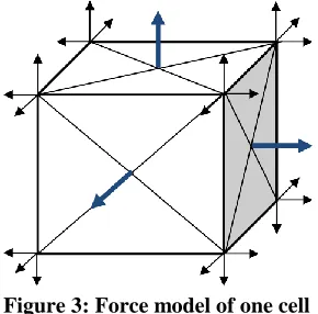
of plant’s cell acting on the walls to sustain the integrity of the cell, the inflation force is modeled as an outward force normal to the walls of the cell. The force acting on the wall surface is then split and distributed equally to the four nodes in the corners of the cell wall. Figure 3 shows the force acting on the walls (blue errors) and there equal distribution over the nodes (black errors). The forces in the nodes are always in the global coordinate system which requires a coordinate transformation of the pressure force in case the cells are deformed or distorted. If multiple cells are connected together, the forces would cancel each other out if just the sum of forces on every node were taken. For this reason, the code evaluates each nodal cell connection and sums up all the applied forces in a line of connected nodes and applies it to the nodes on the edges of inflating cells. It is
also possible to simulate broken cells within the array to observe the deployment behavior and the obtained shape. The inflation force has a linear slope for a constant time t. After that the pressure stays constant but it is also possible to apply a leakage to certain cells or the entire array of cells. This leakage could be caused by micrometeoroid impacts, fabrication errors, degrading of material or natural leakage of an inflatable in the space environment.
Fact - Actuation Force
The actuation of the structure is triggered by changing the pressure within the cells which causes a shape change of the cell membrane. The actuation force is applied in a similar manner then the inflation force. This force can be applied in a specific pattern to trigger a particular responds, for example if the membrane sheet should be folded along one line, this line of cells can be actuated. If micro pumps between the cells are used the air mass is getting transferred between neighboring cells which makes on cell inflate and the other deflate. On the other hand if valves are used, the air mass is transfered only to the cells with a lower pressue until the system is in equilibrium. Similar to the inflation force, an algorith in the code is used to distribute the force amoung the cells to obtain the desired deformation result.
Fext - External Force
[image:5.612.379.524.302.445.2]Depending on the environment the structure is operated in, the external forces vary. The main two application areas that are described here are the space and terrestrial environment. Also their application area changes depending on the nature of the force. Some forces might be only applied to mass nodes, other forces are acting on the inside walls or some are just applied to one surface on the outside of the structure.
6 Space Applications
In space the main external force applied to the structure is gravity, with a gravity gradient for very large structures. Even small gravity gradients can affect the structure due its low pressure lightweight nature. The gravitation force is applied to each node towards the centre of
gravity with a value changing depending on the distance in-between the cells. The gravity force at each node changes at each time step due to the shifting mass due to actuation; this is done through the adaptive mass matrix described above. Another perturbating force is solar radiation pressure (SRP) and atmospheric drag which is applying a force on the surface of the structure. In order to model this force in the code, only the nodes on one surface experience the force. Figure 4 shows a three cell structure moving from left to the right while getting propelled by solar radiation pressure, decelerated by atmospheric drag and pulled downwards by gravity. It can be seen that even though the forces act on a surface or a mass, the forces in the model are distributed over the nodes of the
different cells. These forces are depending on the orientation and the shape of the structure.
Other forces that can be applied to the model are short term impact forces from for example meteoroids or space debris.
Terrestrial Applications
On Earth or planetary bodies, the main force acting on the structure is gravity pulling the structure towards the ground. Therefore also obstacles within the path or pressure changes due to air or water needs to be considered for these applications. Furthermore, impact and vibration forces become much more dominant. Compared to space, the external forces on Earth are changing faster, for example the drag force caused by wind gusts which can change directions rather quickly.
III.
Simulations and Results
To show the functionality of the developed code, two and three dimensional simulations have been carried out which will be described more in detail in the following.
A. Two Dimensional (2D)
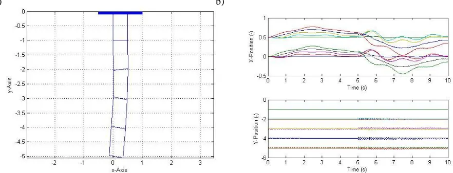
To give an example for the 2D case, the iSEDE8 structure with 5x2 cells from Figure 1 was modeled. Figure 5 shows the multibody simulation with five actuator elements, the element closest to the top is the mounting of the structure to a constrained point. Each of the vertical lines in Figure 5a represents a cell; each horizontal line represents the connection of two cells via a micro pump.
a) b)
[image:6.612.339.537.120.261.2] [image:6.612.78.519.521.690.2]In this simulation, the structure was actuated twice and Figure 5a represents the result after the end of both cycles. In the first actuation cycle, the fist element was actuated with a positive mass flow (from right to left) for five seconds. In the second actuation cycle, the second element was actuated with a negative mass flow that was twice as high. Figure 5b shows the displacement of the connection points of the cells over the two actuation cycles. It can be clearly seen that the structure has a higher displacement into the x direction then the y-direction. This result shows that the developed system is capable of deforming its own shape in the desired, forecasted way. The described code is capable of creating two dimensional shapes of hundreds of actuator elements long.
B. Three Dimensional (3D)
By making the developed code capable of simulating three dimensional structures, the possible applications become countless. To show the functionality of the concept, a full deployment and actuation cycle is outlined here. Common very large structures in space are reflectors, parabolic antennas or concentrators which always need some sort of deployment mechanism. Therefore, a sun concentrator dish was chosen to validate the capabilities of the smart structure. Such a concentrator can be used to focus the sun’s energy on an asteroid directly to ablate the asteroid and therefore change its trajectory9. The dish has to be capable of changing its focal point on the surface of the target. An adaptive concentrator is especially necessary for rotating asteroids with their unusual shape10.
The concentrator was modeled 11 cells long (x-direction), 11 cells wide (y-direction) and 2 cells thick (z-direction) which results in a total of 242 cells and 432 nodes. The odd numbers of cells in x- and y- direction was chosen to ensure that the centre of the structure in the xy-plane is a cell.
Inflation
The inflation of the whole structure is triggered once the structure is released from the carrier spacecraft and subjected to the space environment. As described above, the structure deploys from a single point which corresponds to the stored configuration. The inflation time was taken as four seconds which only impacts the damping characteristics of the structure. For this deployment demonstration it is assumed that every cell is fully functional and that the inflation force is the same for all the cells.
a) b)
Figure 6: a) Inflated 11x11x2 cell array, b) Displacement of x and y and z-position
8
Actuation
After the deployment through inflation formed a flat sheet, the cells are being actuated to form the curved concentrator dish. For the actuation the top cells pump air molecules to the bottom cells to create a positive curvature of the dish. To change the focal point, the structure was actuated twice with the second actuation cycle having twice the air mass exchanged from the top to the bottom layer.
[image:8.612.86.518.142.256.2]a) b) c)
Figure 7: Bottom layer plot of a) inflated structure, b) structure actuated once and c) structure actuated twice
Figure 5 shows the evolution of the deformation due to actuation. To increase the readability of the graphs, only the bottom layer of the full array is displayed in Figure 7. The array in Figure 7a shows the same array then the inflated structure of Figure 6a. Figure 7b is the array after being actuated once and Figure 7c shows the increased curvature of the structure after being actuated twice.
Figure 8: Displacement plot of a) structure actuated once and b) structure actuated twice
The position over time of all the nodes can be seen in Figure 8, Figure 8a shows the structure that was actuated once and Figure 8b shows the structure being actuated twice. In the first four seconds of the simulation the structure was inflated homogenously. After the oscillation has mostly settled down, the first actuation was started at six seconds with a linear increase for four seconds. The second actuation, which can be seen in Figure 8b was started at 12 seconds and also lasted for four seconds with a linear increase.
The displacement curves show clearly that most of the deformation of the structure is occurring in the z-direction which was the desired responds. The observed oscillation of the system is caused by the fast actuation time and the low damping nature of the structure and is highly dependent on the chosen material and application.
External Forces
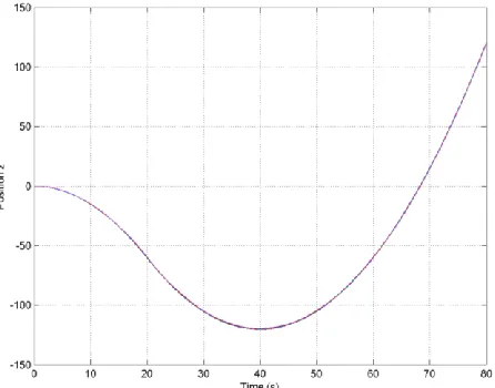
[image:8.612.88.513.350.501.2]asteroid making the gravity the only external force pulling on the structure. For the simulation, the moving coordinate system of the structure without any perturbation is used.
Figure 9 shows the z-axis displacement of all the nodes of the structure over time. From the beginning of the simulation, the solar radiation pressure and the gravity are acting on the model, even though the solar radiation pressure only reaches is maximum force once the structure is inflated and has its maximum surface area. At 20 seconds, the structure moves into the shadow of the asteroid, subjecting the structure only to the gravity of the asteroid. The structure stays in the shadow until the end of the simulation. From Figure 9 it can be seen how the model successfully alters the position of the structure due to the applied forces. At 40 seconds, the gravitational pull of the asteroid is strong enough to overcome the momentum build up by the first twenty seconds of solar radiation pressure. In the last 40 second the gravity of the asteroid is pulling the structure towards its surface resulting in a parabolic shape of the displacement curve.
Control
To control the structure, a simple PID controller has been implemented that is continuously evaluating the deformation of the structure to counteract the perturbation caused by external forces with the actuation of the structure. Current research is focused on implementing an artificial neural network (ANN) to improve the control of the structure. The artificial neural network controller is capable of controlling the shape faster than the current PID controller.
IV.
Conclusion
The concept presented in this paper describes the simulation of a mechanical analog to living plants that are able to follow the path of the sun during a day. The developed structure consists of an array of hyperelastic cells which can change their volume due to changing internal pressure. By inflating specific cells in an array, the structure can be deformed in a desired manner. The code described in this paper discretized each hyperelastic cell with point masses and connecting bending and torsion beams. The inflation force is modeled as a pressure force acting outwards on the cell walls. The presented code is capable of simulating the inflation of the cells and their pressure change in order to facilitate actuation and shape change. External forces like solar radiation pressure, air drag or differential gravity are applied to the inflated structure to simulate the responds of the adaptive structure to the space environment. The developed structure is able to overcome the perturbation caused by the external forces by changing the actuation in order to sustain the same shape all the time. The developed code has application areas ranging from large deformable space structures down to microscopic medical devices, therefore the simulation was undertaken unit less. For every specific application case the entities of the mass, stiffness and damping matrix must be calculated or obtained through experimentation. As an example application, a three dimensional concentrator capable of changing its focal point has been shown.
Acknowledgments
[image:9.612.310.533.103.278.2]We would like to thank all the students involved in the StrathSat-R and iSEDE experiments for their work on the sounding rocket and stratospheric balloon experiments on the topic of inflatable smart space structure. We would also like to thank the European Space Agency (ESA), the German Aerospace Centre (DLR) and the Swedish National Space Board (SNSB) and their experts for their support and giving us the opportunity to fly our experiments on their rockets and balloons as part of the REXUS/BEXUS programme.
10
References
1Mangenot, C., Santiago-Prowald, J., van't klooster, K., Fonseca, N., Scolamiero, L., Coromina, F., Angeletti, P., Politano, M., Elia, C., Schmitt, D., Wittig, M., Heliere, F., Arcioni, M., Petrozzi, M., Such Taboada, M. "ESA Document: Large Reflector Antenna Working Group - Final Report," Technical Note TEC-EEA/2010.595/CM. Vol. 1, 2010.
2
Larson, W. J., & Wertz, J. R. (1992). Space mission analysis and design (No. DOE/NE/32145-T1). Torrance, CA (United States); Microcosm, Inc..
3
Crawley, E. F. "Intelligent structures for aerospace: a technology overview and assessment," AIAA journal Vol. 32, No. 8, 1994, pp. 1689-1699.
4 E. B. Wilson, "The Heliotropism of Hydra", The American Naturalist , Vol. 25, No. 293 (May, 1891), pp. 413-433
5 Sinn, T., Vasile, M., Tibert, G. “Design and Development of Deployable Self-inflating Adaptive Membrane”
AIAA-2012-1517, 13th AIAA Gossamer Systems Forum as part of 53rd Structures, Structural Dynamics, and Materials and Co-located Conferences, Honolulu, Hawaii, 23 - 26 April, 2012
6 Cowan, T., Darling, A., Kruse, M., Llauro, A., Heitel, J., Kellam, C., Ohlson, M., Cheek, W., Lewis, M., VanPelt
III, J., Buckley, D., Crosby, J., Sarisky, M., Argibay, N., Cabera, C., and Nipper, C. "Inflate-A-Brake - A Gossamer Structures Technology Demostrator for De-orbiting Pico-Satellites," FUNSAT Design Competition - Gossamer Gators / University of Florida, 2004.
7 Sinn,T., Hilbich, D. and Vasile, M., “Inflatable Shape Changing Colonies Assembling Versatile Smart Space
Structures”, IAC-13-C2.5.2, 64th International Astronautical Congress (IAC) 2013, 23 – 27 October 2013, Beijing, China
8 Sinn, T., Queiroz, T., Brownlie, F., Leite, L., Allan, A., Rowan, A. and Gillespie, J. ”iSEDE Demonstrator on High
Altitude Balloon BEXUS: Inflatable Satellite Encompassing Disaggregated Electronics”, IAC-13-E2.3, 64th International Astronautical Congress (IAC) 2013, 23 – 27 October 2013, Beijing, China
9 Gibbings, A., Vasile, M., Watson, I., Hopkins, J.M., and Burns, D. "Experimental analysis of laser ablated plumes
for asteroid deflection and exploitation." Acta Astronautica (2012).
10