Int. J. Electrochem. Sci., 14 (2019) 8014 – 8027, doi: 10.20964/2019.08.51
International Journal of
ELECTROCHEMICAL
SCIENCE
www.electrochemsci.org
Novel Glucose Oxidase Interlocked Prussian Blue/Polysulfone
Stereo-Structure and its Application in
Amperometric Glucose
Biosensor
Cang Wang1, Min Pan1, Hang Chen1, Dajing Chen2,*, Yuquan Chen1,*
1 Department of Biomedical Engineering, Zhejiang University, Hangzhou 310027, China 2 Medical School, Hangzhou Normal University, Hangzhou, 311121, China
*E-mail: [email protected]
Received: 25 March 2019 / Accepted: 21 May 2019 / Published: 30 June 2019
In this study, we present a controllable Prussian Blue (PB)- Polysulfone (PSF) stereo-structure with glucose oxidase (GOD) interlocked for glucose biosensing. This work links the electrochemical catalytic properties of PB with the large surface area and mass transport of three-dimensional macro-porous PSF and highlights the importance of interlocking GOD with PB to improve sensor sensitivity and linearity, which also maintains glucose sensor activity. The prepared PB-PSF-GOD glucose biosensor exhibited a 1-12 mM linear range, high affinity and good selectivity with a low applied potential of -0.05 V (vs Ag/AgCl). Furthermore, the prepared sensor only attenuated by 10% after 7 days of continuous testing. The advanced properties of the novel GOD interlocked PB-PSF structure may have promising applications in enzymatic biosensors, especially the continuous glucose monitoring (CGM).
Keywords: Prussian blue; nanostructure; glucose oxidase; glucose biosensor; nanocoating
1. INTRODUCTION
PB, which is a typical hexacyanoferrate coordination compound, is a highly efficient electrode modifier for GOD-based glucose biosensors[8]. It has a stable cubic cell structure and is composed of the following three elements: iron, carbon and nitrogen[9], which make PB a simple metal organic framework (MOF). Similar to other MOFs, PB has exhibited many catalytic properties, such as a tunable cell-structure size, a highly specific surface area and abundant surface functional groups. As previous studies have reported, PB-applied biosensors are able to sense hydrogen peroxide at a low applied potential, which makes PB an “artificial peroxidase” analogous to peroxidase enzymes for hydrogen peroxide reduction[10]. In addition to its catalytic function, PB is also well-known for its nontoxicity and biocompatibility[11]. Due to the above characteristics, PB is widely employed with GOD for glucose biosensors[12].
Together with the development of nanotechnology, porous PB nanostructures are widely adopted in glucose biosensors, taking the place of crystalline powder samples as electrochemical mediators[13-16]. The porous stereo-structures in PB mixtures that link the functional interfaces and nano-PB particles are in a rapidly developing field[10]. Various assembly strategies have been studied for nano-PB-integrated stereo-structures, including direct electrodeposition[17], seed-mediated growth[18], molecular 3D imprinting[19], “electroless” deposition[20] and spontaneous self-assembling. However, most researchers focus on nano-PB itself, ignoring the interactions between nano-PB and substrates. Due to the cooperation between nano-PB and substrates, the sensor as a whole will undergo interesting changes. In particular, substrate materials with special structures are especially worthy of concern. Additionally, the porous structures in flexible substrates are always fragile and the life of the sensor is rarely mentioned[10, 20-22].
In the present work, we report a novel PB-PSF stereo-structure with interlocked glucose oxidase (PB-PSF-GOD) and explore its application as an amperometric glucose biosensor. In contrast to traditional PB deposition, the fabricated PB layer maintains the 3D structure of the PSF substrate and thoroughly covers the inner surface of the substrate with GOD interlocked in the hydrophilic-modified PSF membranes under mild reaction conditions. Additionally, flexible amperometric glucose biosensors based on the PB-PSF-GOD were developed with a great linear range, good selectivity and long life. The results demonstrated that PB-PSF-GOD structures with potential features could be a promising platform for enzymatic biosensors, especially the CGM.
2. EXPERIMENTAL
2.1 Reagents and apparatus
All chemicals used were of analytical grade and were used as received without any further purification. Modified PSF porous membranes were obtained from Harvest company as commercial products. The carbon slurry was purchased from the Acheson colloids company (Product: Electrodag 423SS). Glucose oxidase (EC 232-601-0, from Aspergillus niger) and Bovine serum albumin (BSA) were purchased from Aladdin. Glucose, glutaraldehyde (GA), uric acid (UA), ascorbic acid (AA), hydrochloric acid (HCl), potassium chloride (KCl), ferric chloride (FeCl3), potassium ferricyanide
sodium hydroxide (NaOH), hydrogen peroxide (H2O2) and ProClin 300 were supplied by Sigma-Aldrich
(China). The supporting electrolyte used for the electrochemical studies was 0.05 M phosphate buffer solution (PBS), prepared using Na2HPO4 and NaH2PO4 and the pH was adjusted either using HCl or
NaOH. Glucose solution was stored at 26℃ for 24 h for mutarotation before use. Aqueous solutions were prepared in deionized water (DI). Fresh blood samples were provided from three healthy volunteers and two diabetes patients.
The peristaltic pump used for the bubbling solution was a BT00-100M from the Igpump company. The morphologies of the PSF and PB deposition were studied using a Hitachi SU8010 field-emission scanning electron microscope (SEM). Fourier transform infrared (FT-IR) spectra were recorded with an AVATAR 370 in reflectance mode. All electrochemical measurements were performed on a CHI 660A electrochemical workstation (Shanghai Chenhua, China). A standard three-electrode system was used for all electrochemical experiments, with an Ag/AgCl (1.0 M KCl) electrode and a platinum net (geometric area, 0.96 cm2) as the reference and counter electrode, respectively. PBS (0.1M pH=5) was used as the supporting electrolyte for electrochemical tests. Cyclic voltammetric (CV) curves were obtained at 50mVs-1 and electrochemical impedance spectroscopy (EIS) were carried out at frequency of 1Hz to 105 Hz. Amperometric detection was operated at applied potential of -0.05V. The
serum glucose analyses were conducted using a YSI 2300 STAT PLUS (Yellow Springs Instruments, Ohio, USA). All of the experiments were conducted at room temperature.
2.2 Immobilization of GOD on modified porous PSF membranes
Before the immobilization of GOD, uniform-cut hydrophilic porous PSF membranes (geometric area, 0.30 cm2) were washed by immersing in deionized water for 24 h and dried overnight at room temperature. The GOD solution was freshly prepared by dissolving 15 mg GOD and 8 mg BSA (for GOD protection) in 1 ml deionized water. To immobilize GOD on the modified PSF membrane (Scheme, Fig. 1), an appropriate amount of GOD solution (2 µL) was evenly dropped on top of the modified PSF membrane and dried by sticking absorbing paper on the other side for 1 min. Then, 2 µL of 5% GA solution (for crosslinking) was dropped and dried in the same way. After drying under air at room temperature for 30 min, the resulting membrane was rinsed 3 times with deionized water and dried in drying oven at 40℃ for preparation.
2.3 Synthesis of PB
For the synthesis of PB, a PB self-assembling reaction was carried out (Scheme, Fig. 1) as follows. (i) Prepared membranes were soaked in 0.01 M K3Fe(CN)6 (pH = 4, adjusted by HCl) solution
and bubbled with a peristaltic pump (100 rpm) for 1 min, before being dried with absorbing paper stuck to the bottom surface for 15 min at room temperature. (ii) The K3Fe(CN)6-treated membrane was
gradually immersed into 0.02 M FeCl3 and 0.1 M glucose solution mixture (1:1), then bubbled with the
deionized water and dried in a drying oven at 40℃ for 1 h. To cover the PB on GOD interlocked PSF membrane (Scheme, Fig. 1), this procedure was repeated 15, 30 and 45 times, followed by FTIR spectroscopy.
2.4 Preparation of the modified biosensor
To prepare easily fabricated, flexible amperometric glucose biosensor, an appropriate amount of carbon slurry was brushed on the bottom surface of the membrane.
Figure 1. Schematic for the fabrication of Prussian Blue covered GOD-interlocked porous PSF membranes.
[image:4.596.153.456.224.393.2] [image:4.596.141.456.455.692.2][image:5.596.68.529.71.299.2]
Figure 3. PB covered porous PSF membrane flexibility (with 15 cycles PB synthesis procedure).
[image:5.596.67.532.354.707.2]
Figure 5. FT-IR spectra of the PB formed the procedure being repeated (a) 0 times, (b)15 times, (c) 30 times and (d) 45 times.
After drying overnight in a fume hood at room temperature, paraffin was coated on the bottom to prevent direct contacts between the carbon slurry and the solution. Part of the sensor was protected by plastic plate, leaving a 1 mm diameter hole in contact with the solution. The biosensor was stored in the fridge at 4℃ when not in use. The modified PB-PSF-GOD biosensor maintains great flexibility in the presence of the pasted carbon slurry and wax.
3. RESULTS AND DISCUSSION
3.1 Preparation of PSF-GOD and PB-PSF-GOD
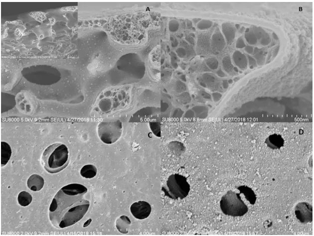
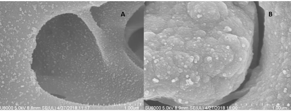
Previously, PEDOT or graphit foam [14, 20] with three dimensional macroporous structure was used as the matrix to grow PB nanoparticles. Here, another important polymer PSF was used to support PB. Fig. 2a, c, d and Fig. 4a show the SEM images of the modified PSF film. The low magnified image shows the PSF film has a network type morphology with micron-sized pores (Fig. 2c). Highly magnified image indicates these macropores are interconnected, which could facilitate mass transport[19, 20, 23] and provides a large surface area for reaction and enzyme immobilization. Moreover, lots of fiber-like structures and extruded tubular structures cross-linked with each other in the PSF film (Fig. 2a, up-left), which could provide great active sites for GOD bonding.
Next, Nano-PB particles were formed on this PSF matrix through a spontaneous reaction between FeCl3 and K3Fe(CN)6 in the presence of a slight excess of H2O2, as Liu[24] published, due to the high
open potential (+1.22 V) in the FeⅢ − FeⅢ(CN)6 state[25]. The PB formation reaction can be expressed as follows:
2𝐹𝑒3++ 2𝐹𝑒(𝐶𝑁)
6
3−+ 𝐻
[image:6.596.104.492.79.279.2]
Here, instead of directly mixing [24], H2O2 was gradually generated in a reaction with glucose
and immobilized GOD (Formula 2), which is trapped in PSF flexible membrane and protected by the GA and BSA composite. The formation can be described as Formula 3.
Glucose + 𝑂2GOD→ Gluconolactone + 𝐻2𝑂2 (2)
2𝐹𝑒3++ 2𝐹𝑒(𝐶𝑁)63−+ Glucose + 2𝐾+ → 2𝐾𝐹𝑒[𝐹𝑒(𝐶𝑁)6] + 2𝐻++ Gluconolactone (3)
Combine the SEM and subsequent electrochemical results (Fig. 2a,b,d and Fig. 5), a layer of well dispersed PB particles uniformly anchor on the PSF membrane instead of traditional PB bulk deposition[8, 14, 21, 26]. The average size of these particles is about 100nm. During preparation, the entrapped GOD may have three functions. First, GOD as a glucose-sensitive agent produce H2O2 to
initiate the spontaneous growth of PB. To demonstrate the active role of the GOD, experiment revealed that almost no PB was generated on PSF within 30 min if immersing just BSA interlocked PSF film in the growth solution of PB. Second, the GOD provides insufficient nucleis for the crystallization process to generate PB particles with small size and improved dispersity. This may be explained with the nonclassical seed-mediated growth theory[27]. First, quantities of low solubility Prussian blue nuclei were formed in the closest place to the interlocked GOD. Once a new particle is nucleated, the hydrogen peroxide gradient drives it to the gap between two particles with glucose as nanocrystallite stabilizer[18]. This was confirmed by the facts that spherical PB with aggregation was formed on PSF film if the glucose concentration in PB precursor solution increased from 0.1M to 1M (Fig. S1), and the flocculation was formed as soon as H2O2 added into the precursor solution. Third, the GOD provides great selectivity
and sensitivity in prepared glucose sensor (Fig. 7,8).
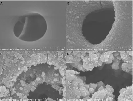
3.2 Effects of reaction cycles on PB generation
To optimize the formation of the PB layer, the membranes were produced with different reaction cycles (ranging from 0 to 45). As shown in Fig. 4, obvious PB deposition grows as the number of reaction cycles increases. At 45 cycles, the original PSF macropores were blocked with stacking PB deposition, which is likely attributed to the excess crystallization speed for seed formation on the inner surface of the pores[8]. The FT-IR spectra of the PB layer morphologies formed by various cycles were illustrated in Fig. 5. These results further confirmed that the PB nanoparticles successfully covered the porous PSF membrane. In the FT-IR spectrum of PB layer forming with 1 cycle, a new sharp absorption peak appeared at 2079.9 cm−1 on the PB covered PSF surface compared with the original PSF surface. This peak corresponded to the CN stretching absorption band of the PB Fe2+-CN-Fe3+ CN group[28].
Additionally, there was no peak at 2168 cm−1, which was characteristic of a Berlin green Fe2+ -CN-Fe3+ bond[29], revealing that no Berlin green (which has a similar structure to PB) was formed on the
surface of the electrode. The peaks at 2070.8 cm−1 and 2062.6 cm−1, which correspond to PB layer forming with 15 and 45 cycles, respectively, are characteristic Fe2+-CN-Fe3+ absorption peaks. The peaks
3.3 Electrocatalytic response to glucose on PB-PSF-GOD sensor
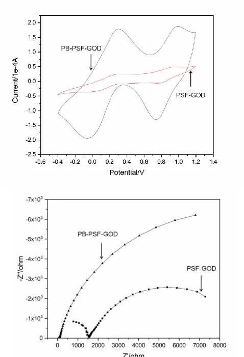
The as-prepared membrane with embedded GOD, well dispersed PB nanoparticles combined with three dimensional porous PSF as matrix may have great potential in glucose sensor fields. As an important indicator, the activity of the PB-PSF-GOD membrane for H2O2 catalytic reduction was
evaluated. Fig. 2A shows the CVs obtained on PB-PSF-GOD and PSF-GOD membranes modified sensors for 0.4mM H2O2 at the potential range from -0.4V to 1.2V in 0.1M PBS (pH=5). Fig. 2B displays
the real and imaginary part of the EIS spectra represented as Nyquist polts for PB-GOD and PSF-GOD membranes modified sensors at frequency of 1Hz to 105 Hz using 0.1M KCl (pH=5.0) as the electrolyte. The PB-PSF-GOD has (a) larger current response, (b) lower resistance of charge transfer: the high frequency part of EIS curve of PB-PSF shows a much smaller diameter than that of PSF-GOD and (c) enhanced mass transfer: the slope of the linear part of PB-PSF-GOD EIS curve is higher than the value of PSF-GOD. The results of CV and EIS demonstrate that introducing the PB-PSF structure largely improves the catalysis for H2O2 reduction, which means PB-PSF-GOD glucose sensors may have higher
sensitivity.
Figure 6. (A) CVs of 0.4mM H2O2 on PB-PSF-GOD and PSF-GOD in 0.1M PBS (pH=5.0). Scan rate:
0.05 Vs-1. (B) EIS of 0.4mM H2O2 on PB-PSF-GOD and PSF-GOD in 0.1M KCl (pH=5.0) at
[image:8.596.177.416.327.677.2]
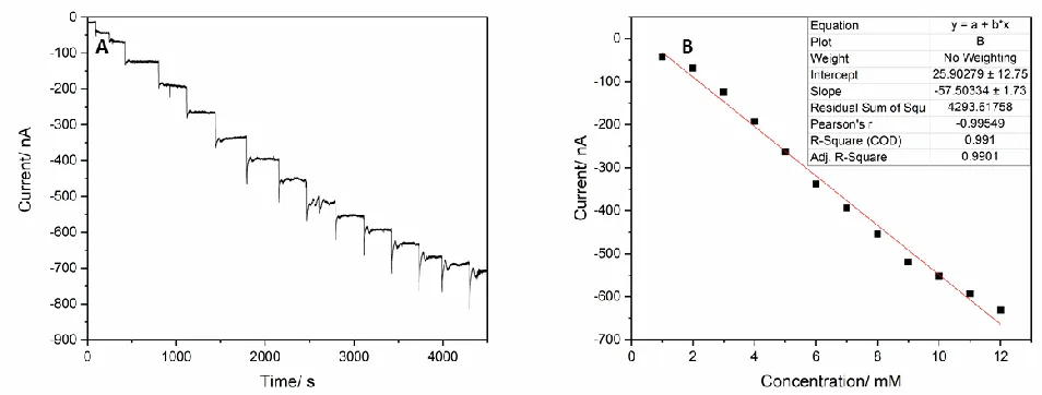
Figure 7. The amperometric responses of the PB-PSF-GOD biosensor to successive injection of 1 mM glucose from 0mM to 15mM in 0.05 M PBS (pH=6.5, room temperature, including 0.1 M KCl) at -0.05 V (vs. Ag/AgCl). The inset figure displays the corresponding calibration curve for glucose from 0 mM to 12 mM.
As described in 2.4, PB-PSF-GOD glucose biosensors were fabricated to evaluate its glucose analytical performance by amperometric measurements in 0.05 M PBS (pH 6.5, room temperature, including 0.1 M KCl) at an applied potential of -0.05 V (vs. Ag/AgCl) according to published study [21, 31]. The amperometric response curve for the PB covered glucose biosensor with the successive addition of glucose (1.0 mM/step) is shown in Fig. 7. Each injection was followed by stirring (200 rpm with a magnetic stirrer) for 60 s to homogenize the solution. This procedure corresponds to the sharp decline and little rebound at the beginning of each step in the curve. To verify the steady-state current for each step, each concentration was measured for 5-10 min. As the glucose concentration increased, the response current of the biosensor decreased with a linear response up to 12 mM until an obviously nonlinear current response was observed at 15 mM, which suggests saturation of the enzyme reaction. The corresponding calibration curve for the glucose response is shown in inset picture in Fig. 7. The biosensor exhibited a large linear range from 0 mM to 12 mM with a correlation coefficient of 0.991 and a sensitivity of 0.191 µAmM-1cm-2. Compared with previously reported glucose biosensors (Table 1), the present biosensor extended the linear range to physiologically relevant concentration windows without a barrier layer.
As an enzyme-based biosensor, the PB-PSF-GOD glucose biosensor also followed Michaelis-Menten kinetics. The Michaelis-Michaelis-Menten constant, KM, was calculated from the amperometric response
curve to analyze the biosensor’s glucose response behavior. The electrochemical-driven GOD catalysis Michaelis-Menten kinetics equation can be written as follows (Formula 4)[32]:
v =𝑣𝑚𝑎𝑥𝐶𝑠
𝐶𝑠+𝐾𝑀 (4) where KM is the Michaelis-Menten constant, CS is the glucose concentration in the solution, v is
the initial velocity of the reaction and vmax is the maximum reaction velocity. Using Lineweaver-Burk
[image:10.596.49.563.160.359.2]
of free GOD[33, 34] (33mM-110mM) and immobilized GOD[21] (0.44 mM). This further confirming the fewer defects, higher GOD affinity for the PB-PSF-GOD.
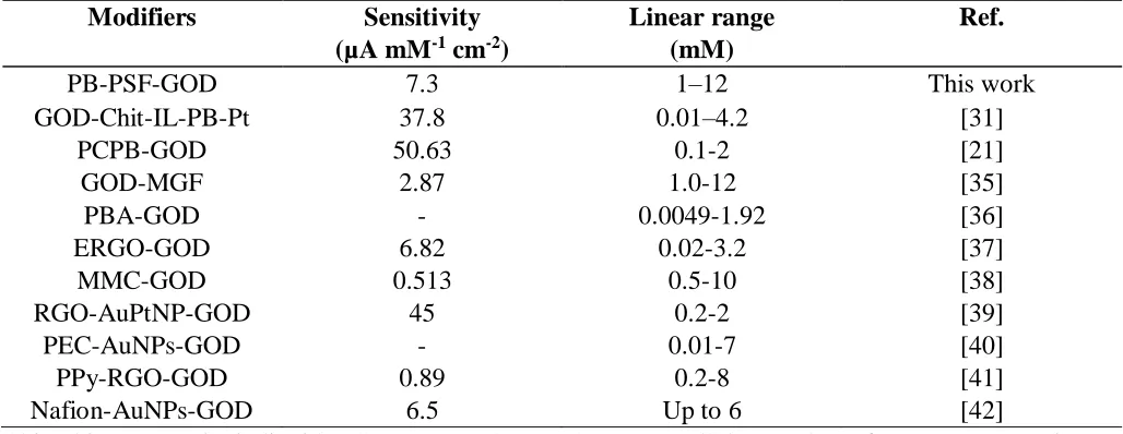
Table 1. Comparison of the performance of various PB-modified glucose biosensors.
Modifiers Sensitivity (µA mM-1 cm-2)
Linear range (mM)
Ref.
PB-PSF-GOD 7.3 1–12 This work
GOD-Chit-IL-PB-Pt 37.8 0.01–4.2 [31]
PCPB-GOD 50.63 0.1-2 [21]
GOD-MGF 2.87 1.0-12 [35]
PBA-GOD - 0.0049-1.92 [36]
ERGO-GOD 6.82 0.02-3.2 [37]
MMC-GOD 0.513 0.5-10 [38]
RGO-AuPtNP-GOD 45 0.2-2 [39]
PEC-AuNPs-GOD - 0.01-7 [40]
PPy-RGO-GOD 0.89 0.2-8 [41]
Nafion-AuNPs-GOD 6.5 Up to 6 [42]
Chit, chitosan; IL, ionic liquid; PC, porous carbon; MGF, Mesocellular graphene foam; PBA, Prussian blue analogue; -, not mentioned; ERGO, Electrochemically reduced GO; RGO, Reduced graphene oxide; AuPtNP, Gold and platinum alloy nanoparticle; PEC, polyelectrolyte complex; AuNPs, gold nanoparticles; PPy, polypyrrole.
The biosensor was stored in the fridge at 4℃ when not in use. The stability of the biosensor was investigated by measuring the electrode response with 6 mM glucose solution every day. It was found that the biosensor retained 85% of the original response after 40 days, which indicated good stability of the biosensor.
3.4 Anti-interferent test
Figure 8. Amperometic response for 0.1mM AA, 0.1mM UA and 1.0mM glucose on the PB-PSF-GOD biosensor in 0.1 M PBS (pH=6.5, including 0.1 M KCl). Applied potential: -0.05V.
3.5 Human serum samples analyse
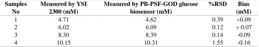
To further assess the performance of the PB-PSF-GOD glucose biosensor in blood samples, we measured glucose concentrations in fresh human serum samples after centrifuging (2000rpm, 5 min). The detected glucose concentrations in serum samples were derived from the standard curve, the regression equation and single point calibration (using one healthy volunteer serum sample). Bias values were determined by comparing glucose concentration estimated by PB-PSF-GOD glucose biosensor and YSI 2300 (Table 2). The results indicate that the PB-PSF-GOD glucose biosensor has the potential for human blood glucose determination.
Table 2. Analysis results in serum samples (N = 5).
Samples No
Measured by YSI 2300 (mM)
Measured by PB-PSF-GOD glucose biosensor (mM)
%RSD Bias (mM)
1 4.71 4.62 0.39 +0.09
2 6.02 6.09 0.12 + 0.07
3 8.30 8.39 0.14 -0.09
4 10.15 10.31 1.55 -0.16
3.6 Continuous testing in serum samples
[image:11.596.49.550.534.625.2][image:12.596.123.479.159.268.2]
continuous testing (Table 3). The results indicate that PB-PSF-GOD glucose biosensor has potential applications in CGM.
Table 3. Continuous testing results in serum samples.
Time (h) 1 24 48 72 96 120 144 168 192
Sample 1 -345 -240 -242 -239 -238 -235 -232 -230 -228
Sample 2 -565 -397 -396 -395 -394 -384 -382 -380 -370
4. CONCLUSIONS
In conclusion, a novel PB-PSF stereo-structure with interlocked GOD was fabricated, and a good performance glucose biosensor was developed based on this structure. With GOD interlocked in the porous hydrophilic modified PSF membranes, a self-assembled PB layer was formed around the substrate. Fifteen reactions cycles were proven to be the optimal procedure forming well-dispersed PB layer. The experiments revealed that the PB-PSF-GOD glucose biosensor had large linear range, high affinity, good selectivity and long sensor life. The PB-PSF-GOD glucose biosensor may have promising applications in enzymatic biosensors, especially the CGM.
SUPPORTING MATERIAL:
[image:12.596.57.562.487.681.2]
ACKNOWLEDGMENTS
This research was supported by the Zhejiang Provincial Natural Science Foundation of China (Grant No. LY18H180009) and the Zhejiang Province Key R&D Project (Grant No. 2017C03029).
References
1. B. Guerci, M. Floriot, P. Böhme, D. Durain, M. Benichou, S. Jellimann and P. Drouin, Diabetes care, 26 (2003) 582.
2. P. Schaepelynck-Belicar, P. Vague, G. Simonin and V. Lassmann-Vague, Diabetes & metabolism, 29 (2003) 608.
3. M. C. Moreno-Bondi, O. S. Wolfbeis, M. J. Leiner and B. P. Schaffar, J. Anal. Chem.,62 (1990) 2377.
4. J. Wang, Chemical reviews, 108 (2008) 814.
5. D. Olczuk and R. Priefer, Diabetes Metab Syndr, 12 (2018) 181.
6. Y. Luo and Y. Bao, P. Zhang, D. Zhu, X. Li, J. Ji, H. Zhang and L. Ji, Diabetes Technology&Therapeutics, 19(2017)13.
7. I. Lee, N. Loew, W. Tsugawa, C.E. Lin, D. Probst, J. T. La Belle and K. Sode, Bioelectrochemistry,121 (2018) 1.
8. Z. Chu, Y. Liu and W. Jin, J. Biosens. Bioelectron., 96 (2017) 17. 9. K. Itaya, I. Uchida and V. D. Neff, J. Acc. Chem. Res.,19 (1986) 162.
10. B. Kong, C. Selomulya, G. Zheng and D. Zhao, Chemical Society Reviews, 44 (2015) 7997. 11. T. Yamamoto, N. Saso, Y. Umemura and Y. Einaga, J. Am. Chem. Soc., 131 (2009) 13196. 12. A. A. Karyakin, E. E. Karyakina and L. Gorton, J. Anal. Chem., 72 (2000) 1720.
13. P. Yang, J. Peng, Z. Chu, D. Jiang and W. Jin, J. Biosens. Bioelectron., 92 (2017) 709.
14. Y. Zhang, B. Huang, F. Yu, Q. Yuan, M. Gu, J. Ji and Y. Zhang, Y. Li, Microchimica Acta, 185 (2018) 86.
15. L. Wang, S. Tricard, P. Yue, J. Zhao, J. Fang and W. Shen, J. Biosens. Bioelectron., 77 (2016) 1112.
16. M. A. Komkova, E. E. Karyakina and A. A. Karyakin, J. Anal. Chem., 89 (2017) 6290. 17. D. Feng, X. Lu, X. Dong, Y. Ling and Y. Zhang, Microchimica Acta, 180 (2013) 767.
18. X.J. Zheng, Q. Kuang, T. Xu, Z.Y. Jiang, S.H. Zhang, Z.X. Xie and R.B. Huang, The Journal of Physical Chemistry C, 111 (2007) 4499.
19. X. Mu, T. Bertron, C. Dunn, H. Qiao, J. Wu, Z. Zhao and C. Saldana, H.J. Qi, Materials Horizons, 3 (2017) 442.
20. M. Yang, Y. Liu, Y. Song, G. Zhao, H. Tan, Q. Zhang and F.G. Xu, Int. J. Electrochem. Sci, 12 (2017) 4428.
21. B. Thakur, X. Guo, J. Chang, M. Kron and J. Chen, Sensing and Bio-Sensing Research, 14 (2017), 47.
22. S. Cinti, R. Cusenza, D. Moscone and F. Arduini, Talanta, 187 (2018) 59.
23. E. L. G. Medeiros, A. L. Braz, I. J. Porto, A. Menner, A. Bismarck, A. R. Boccaccini, W.C. Lepry, S.N. Nazhat, E.S. Medeiros and J.J. Blaker, J. ACS Biomate. Sci. Eng., 2 (2016) 1442. 24. P. A. Fiorito, V. R. Gonçales, E. A. Ponzio and S. I. C. de Torresi, J. Chem. Commun., (2005)
366.
25. W. Zhang, L. Wang, N. Zhang, G. Wang and B. Fang, Electroanalysis, 21 (2009) 2325. 26. Y. Xu, Z. Chu, L. Shi, J. Peng and W. Jin, Sensors and Actuators B: Chemical, 221 (2015)
1009.
27. Y. Cheng, J. Tao, G. Zhu, J. A. Soltis, B. A. Legg, E. Nakouzi, J. Deyoreo, M.L. Sushko and J. Liu, Nanoscale, 10 (2018) 11907.
(1994) 1867.
29. P. K. Lee, P. M. Nia and P. M. Woi, Electrochimica Acta, 246 (2017) 841.
30. T. Huang, M. Zhang, L. Cheng, L. Zhang, M. Huang, Q. Xu and H. Chen, RSC Advances, 3 (2013) 25982.
31. Y. Zhang, Y. Liu, Z. Chu, L. Shi and W. Jin, Sensors and Actuators B: Chemical, 176 (2013) 978.
32. S. Krishnan, J. B. Schenkman and J. F. Rusling, J. Biol. chem., 115 (2011) 8371. 33. Q. H. Gibson, B. E. Swoboda and V. Massey, J. Biol. chem., 239 (1964) 3927. 34. B. E. Swoboda and V. Massey, J. Biol. chem., 240 (1965) 5.
35. H. Li, Y. Wang, D. Ye, J. Luo, B. Su, S. Zhang and J.L. Kong, Talanta, 127 (2014) 255. 36. Y. Song, J. He, H. Wu, X. Li, J. Yu, Y. Zhang and L. Wang, Electrochimica Acta, 182 (2015)
165.
37. L. Liu, Y. Gou, X. Gao, P. Zhang, W. Chen, S. Feng and Y.D. Li, Materials Science and Engineering: C, 42 (2014) 227.
38. A. H. Valekar, B. S. Batule, M. I. Kim, K.H. Cho, D.Y. Hong, U.H. Lee, J.S. Chang, H.G. Park and K.Y. Hwang, J. Biosens. Bioelectron., 100 (2018) 161.
39. X. Xuan, H. S. Yoon and J. Y. Park, J. Biosens. Bioelectron., 109 (2018) 75.
40. I. Rassas, M. Braiek, A. Bonhomme, F. Bessueille, G. Raffin, H. Majdoub and N.R. Jaffrezic, Sensors, 19 (2019) 154.
41. B. Wu, S. Hou, Y. Xue and Z. Chen, Nanomaterials, 8 (2018) 993.
42. S. Zhao, K. Zhang, Y. Bai, W. Yang and C. Sun, Bioelectrochemistry, 69 (2006) 158.
43. S. Husmann, E. Nossol and A. J. G. Zarbin, Sensors and Actuators B: Chemical, 192 (2014) 782.