Int. J. Electrochem. Sci., 13 (2018) 6451 – 6461, doi: 10.20964/2018.07.13
International Journal of
ELECTROCHEMICAL
SCIENCE
www.electrochemsci.org
Microstructure and Corrosion Properties of ZK60 Alloys
Modified by Micro-Arc Oxidation Coatings Using
Phosphate-Borate Electrolyte in KOH Solution
Shangjun Ma1,2, Taolei Wang2, Liwei Qian2, Zhen Xiang2, Wei Lu2 and Huawei Yang1,*
1
Department of Stomatology, Affiliated Shanghai Tenth People’s Hospital, Tongji University, Shanghai 200072 China
2
School of Materials Science and Engineering, Shanghai Key Laboratory of D&A for Metal-Functional Materials, Tongji University, Shanghai 201804, China
*
E-mail: yanghuawei@tongji.edu.cn
Received: 10 March 2018 / Accepted: 18 April 2018 / Published: 5 June 2018
In this work, Na3PO4 (0.05 M) and Na2B4O7 (0.02 M) were used as basic electrolytes for fabricating
micro-arc oxidation coatings on ZK60 magnesium alloy. The effects of KOH concentrations (0.01, 0.05, and 0.1 M) on microstructure, chemical composition, and corrosion resistance were systematically investigated. The results revealed that MAO-coated samples prepared in 0.05 M aqueous KOH possessed relatively low thickness (8.82 µm), small pore size (3.33 µm), and the lowest porosity (5.156×10⁻³ pores/µm2). Also, there were no evident microcracks in MAO coatings prepared in 0.05 M aqueous KOH and the pore distribution was uniform. The resulting corrosion characteristics of MAO-coated ZK60 alloys in simulated body fluid solution (SBF) were significantly affected by the KOH concentration. ZK60 alloy coated with MAO prepared in 0.05 M KOH had relatively high self-corrosion potential (-1.28 V), highest polarization resistance (2667.23 kΩ·cm2), lowest corrosion current density (4.36×10⁻⁷ A·cm-2), and low corrosion rate (1.00×10⁻⁵ mm·yr-1), indicating the highest corrosion resistance in SBF and suggesting that MAO coatings prepared in 0.05 M KOH provided effective protection from corrosion for magnesium alloys.
Keywords: Magnesium alloys, Micro-arc oxidation, morphology, corrosion resistance
1. INTRODUCTION
alloys [8–11]. Advantages, including good adhesion of coatings to the substrate, easy control, environmentally-friendly processing, and low cost, have made this approach valuable.
To date, the characteristics of MAO coatings have been investigated and found to be influenced significantly by the process parameters [12–14], electrolyte [15–17], and substrate chemical composition [18–21]. Once the substrate materials and process parameters are fixed, the electrolyte is crucial to MAO coating properties. The concentration and chemical composition of electrolytes influence MAO coating morphology, such as pore size, shape and distribution, coating formation kinetics and composition, and substrate corrosion protection. Choosing the correct electrolyte can reduce coating micropores and microcracks [22] and, consequently, enhance corrosion protection for Mg alloys. Dou has fabricated MAO coatings in silicate and calcium phosphate-based electrolytes on Mg-1.74Zn-0.55Ca alloys [23], and found that CaP-containing MAO coatings more sufficiently protect magnesium alloys from corrosion in long-term immersions. Similarly, Ghasemi have studied the influence of different electrolytes, including Na2SiO3, Na3PO4, and NaAlO2, with KOH addition on
MAO coatings on AM50 alloys [22]. Results have indicated that MAO coatings obtained in Na2SiO3
electrolyte show better corrosion resistance from the formation of a thicker coating with less porosity. Notably, it has been found that an alkaline electrolyte is commonly applied in the MAO process for magnesium alloys while metal dissolution occurs in acid electrolytes. Li have studied the influence of NaOH addition in electrolytes on coating chemical composition, surface morphology, and corrosion resistance [24]. They found that NaOH addition promoted the formation of uniform and stable coatings and resulted in great improvements in corrosion protection for Mg substrates. However, defects, such as microcracks and micropores, still hinder corrosion protection by MAO coatings for magnesium alloys. Therefore, the goal of this study was to determine the correct electrolyte for modifying surface morphology to enhance coating corrosion protection.
In this study, phosphate-borate electrolytes with different KOH content were used to fabricate MAO coatings on ZK60 Mg alloys. Borate addition has been reported to result in MAO coating formation with high microhardness and good crystallinity [25]. Also, borates accelerated coating formation by providing oxygen through decomposition. It has been suggested that, with increased KOH concentration, electrolyte conductivity and viscosity increase and the ignition/breakdown voltage decreases, thereby generating homogeneous MAO coatings with large corrosion resistance [26–27]. Thus, in this study, the effects of KOH concentrations on the microstructure and corrosion resistance of MAO coatings on ZK60 Mg alloys were investigated in detail.
2. EXPERIMENTAL
2.1. Preparation of MAO coatings
Samples were fabricated from an alloy ingot of ZK60 Mg alloy. First, 20×20×5 mm samples were cut and provided a smooth surface by grinding and polishing with SiC abrasive papers (to mesh 2000). A 1.5 mm-diameter hole was drilled in one side of the samples to ensure the stable current passing into the specimens and solution.
with KOH at different concentrations (0.01, 0.05, and 0.1 M). The MAO process was carried out for 15 min at room temperature in a water-cooled stainless steel tank. The anode was the submersed magnesium substrate and the counter electrode the stainless steel tank. The electrical parameters, including a positive constant voltage, negative constant voltage, duty cycle, and pulse frequency, were 350 V, 20 V, 30%, and 600 Hz, respectively. Finally, MAO-coated samples were rinsed in distilled water and ethanol and dried in air at room temperature.
2.2. Characterization of MAO coatings
The surface and cross-section morphologies of MAO coatings were characterized using a scanning electron microscope (SEM, Quanta 200 FEG, FEI Company, Hillsboro, OR, USA). The phase structure of the coating was investigated by X-ray diffraction (DX-2700, Fangyuan, Dandong, China) with Cu-Kα radiation at a scanning speed of 0.03°/s.
2.3. Electrochemical measurements
Electrochemical measurements were conducted using a standard three-electrode cell (CHI600, CH Instruments, Shanghai, China). A saturated calomel act was the reference electrode, the counter electrode graphite, and the sample the working electrode. The experimental temperature was held kept at 37 ±0.5°C and the area of the working electrode at 20×20 mm. A simulated body fluid solution (SBF, composition in Table 1) was used as the electrolyte for potentiodynamic polarization studies, which were performed from -2 to 0 V and at a scanning rate of 0.5 mV/s. Electrochemical impedance spectroscopic (EIS) experiments were performed with an open circuit potential with an AC amplitude of 5 mV in a frequency range varying from 105 to 10-2 Hz. Prior to measurement, samples were immersed in SBF for 20 min to maintain a stable open potential.
2.4 Immersion test
[image:3.596.192.403.648.770.2]Immersion tests were performed to evaluate the biodegradability in vitro of these samples. The pH was 7.4 ±0.2, and temperature 37 ±0.5°C, with the use of a water bath, and samples immersed in 100 ml of SBF for 14 d. During immersion tests, the solution pH and sample weights were recorded every 48 h. A blank SBF was used as the control.
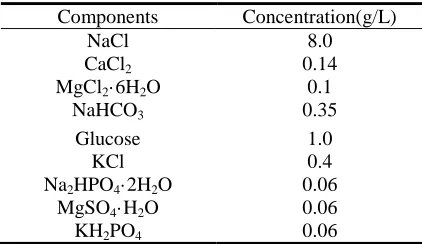
Table 1. Chemical composition of the simulated body fluid (SBF) solution
Components Concentration(g/L)
NaCl 8.0
CaCl2 0.14
MgCl2·6H2O 0.1
NaHCO3 0.35
Glucose 1.0
KCl 0.4
Na2HPO4·2H2O 0.06
MgSO4·H2O 0.06
3. RESULTS AND DISCUSSION
3.1. Effects of KOH concentrations on the composition of the MAO coatings
10 20 30 40 50 60 70 80 90
2Thea
0.01M KOH
Intensity
0.05M KOH
g MgO
0.1M KOH
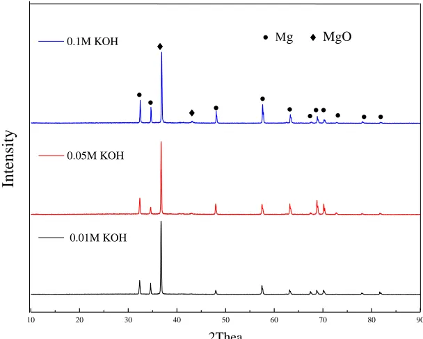
Figure 1. XRD patterns of the MAO coatings prepared in different KOH concentrations (0.01M, 0.05M and 0.1M)
XRD results from ZK60 Mg alloys with MAO coatings fabricated at different KOH concentrations showed clearly that the main component of the coatings was the MgO phase (Fig. 1), without any other impurities, such as Mg3(PO4)2 phase, in the coatings [28–30], which was in
agreement with the results obtained by Liang [31] and Lee [32]. During the MAO process, borate offers oxygen, from B4O72- decomposition, for reactions with metal cations in the electric field,
resulting in rapid growth of the oxide layer on ZK60 substrates [33]. In this micro-arc oxidation process, various possible reactions occurred as follows
Mg→Mg2+
+2e- (1)
4OH-→O2↑+2H2O+4e- (2)
2H2O→2H2↑+O2↑ (3)
2Mg+O2→2MgO↓ (4)
Mg2++OH-→Mg(OH)2↓ (5)
Mg(OH)2→MgO↓+H2O (6)
The relative contents of MgO phase in MAO coatings were investigated by evaluating the relative intensity (IMgO/IMg) of the MgO and Mg phases from XRD patterns. The relative intensities
[image:4.596.146.450.128.372.2][image:5.596.84.508.90.394.2]
3.2. Effects of KOH concentrations on the surface and cross-sectional morphologies
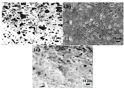
Figure 2. SEM micrographs of the MAO coatings prepared in varied KOH concentrations(a–c: 0.01, 0.05, and 0.1 M KOH, respectively)
The surface morphologies of MAO coatings prepared in various KOH concentrations showed that cracks and pores were distributed on the coatings, forming a rough surface (Fig. 2). The oxide melted and gas was released from micro-arc oxidation discharge channels, resulting in pore formation [34]. Also, fast cooling molten oxides in the electrolyte at a relatively low temperature contributed to the generation of thermal stresses inside oxide films, and microcracks formed due to stress relief. Rough coating surfaces were ascribed to alternating melting and sintering. However, nearly no visible microcracks existed in MAO coating fabricated in 0.05 M KOH, while many more cracks were found in the surfaces of the other two samples.
From the cross-sectional morphologies of MAO coatings fabricated in various KOH concentrations, it was inferred that electric spark discharge dominated the MAO process because of the existence of melts (Fig. 3). In addition, MAO coatings were clearly all composed of two layers: an inner compact layer and an outer layer with pores.
appearances of different spark features, including electric spark discharge frequency, size, and number of sparks that occurred in the spark discharge process of micro-arc oxidation. This resulted in a large number of microcracks and micropores on the MAO coatings [36].
Figure 2. Cross-sectional morphologies of the MAO coatings prepared in different KOH
[image:6.596.127.470.137.291.2]concentrations (a–c: 0.01, 0.05, and 0.1 M KOH, respectively)
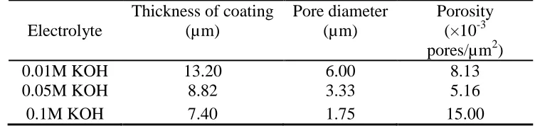
Table 2. Characteristics of the MAO coatings fabricated in different KOH concentrations
Electrolyte
Thickness of coating (µm)
Pore diameter (µm)
Porosity (×10-3 pores/µm2)
0.01M KOH 13.20 6.00 8.13
0.05M KOH 8.82 3.33 5.16
0.1M KOH 7.40 1.75 15.00
3.2. Effects of KOH concentration on the corrosion resistance of the MAO-coated ZK60 alloys
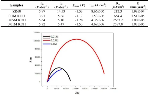
The potentiodynamic polarization curves of MAO-coated ZK60 alloys prepared at different KOH concentrations are shown in Figure 4. The anodic Tafel slope (βa), cathodic Tafel slope (βc),
corrosion current density (Icorr), corrosion potential (Ecorr), corrosion rate (Pi), and polarization
resistance [37] (Rp) values are compiled in Table 3. As the KOH concentration in the electrolyte
[image:6.596.108.484.393.482.2]
to the good surface quality of micro-arc oxidation coatings prepared in 0.05 M KOH, which produced the lowest porosity, uniform pore size, no microcracks, and highest MgO phase content.
0.0 -0.2 -0.4 -0.6 -0.8 -1.0 -1.2 -1.4 -1.6 -1.8 -2.0 -9
-8 -7 -6 -5 -4 -3 -2 -1 0
Potential(V)
log(i/A)
ZK60 0.01M KOH 0.05M KOH 0.1M KOH
Figure 4. Potentiodynamic polarization curves of the MAO coatings prepared in different KOH concentrations
Table 3. Electrochemical corrosion properties of coating samples
Samples βa (V·dec-1)
βc
(V·dec-1) Ecorr (V) Icorr (A·cm
-2
) (kΩ·cmRp 2
)
Pi
(mm·year-1)
ZK60 5.97 14.53 -1.53 8.66E-06 212.3 1.98E-04
0.1M KOH 3.91 5.66 -1.17 1.53E-06 654.4 3.51E-05
0.05M KOH 5.64 5.10 -1.28 4.36E-07 2667.2 1.00E-05
0.01M KOH 5.72 5.47 -1.53 4.69E-07 2587.8 1.07E-05
[image:7.596.178.417.120.306.2] [image:7.596.54.552.394.718.2]
0.01 0.1 1 10 100 1000 10000 100000
10 100 1000 10000 100000 1000000
Z
f (Hz)
0.01M 0.05M 0.1M
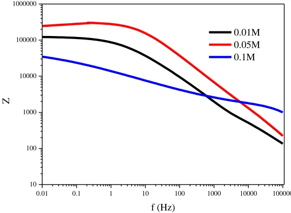
[image:8.596.154.441.74.284.2]Figure 6. Bode plots of the MAO coatings prepared in different KOH concentrations
Figure 7. Equivalent circuit for fitting the EIS plots of the MAO coatings prepared in different KOH concentrations
Nyquist plots of samples prepared by micro-arc oxidation in different KOH concentrations in SBF showed that the diameter of the impedance arc of MAO coatings prepared in 0.05 M KOH was significantly larger than that of the other samples (Fig. 5), indicating that its corrosion impedance was the greatest. The Bode plot of MAO coatings on ZK60 alloy samples prepared in different KOH concentrations showed that the impedance of all samples decreased with increased frequency over the range of 0.01–100000 Hz (Fig. 6). MAO-coated samples prepared in 0.05 M KOH exhibited the highest impedance in almost the whole frequency range. A model was proposed to fit the EIS plots [38], in which Rs represented the solution resistance, R1 the resistance of outer coating layer in parallel
with constant phase element CPE1, which was exposed to the corrosive solution, and R2 in parallel
with CPE2 the resistance of the inner coating layer, including that of the coating/substrate interface
[image:8.596.173.426.334.469.2]
the outer porous layer R1 and one order of magnitude higher than that of the ZK60 alloy substrate
[image:9.596.81.514.262.349.2](~1.414×104 Ω∙cm2). Reducing the KOH concentration led to decreased electrolyte conductivity and reduced spark discharge on substrate surfaces, which contributed to the formation of micro-arc oxidation coatings with fewer surface pores and cracks. The sample prepared by micro-arc oxidation in 0.05 M KOH exhibited the lowest porosity, uniform pore distribution, and nearly no microcracks, which effectively prevented substrate erosion caused by infiltration of corrosive fluids into the pores, thus protected the magnesium alloy. These results were consistent with previous electrochemical polarization data.
Table 4. Fitting results of the MAO coatings for EIS plots from Figures 4 and 5
Samples Rs (Ωcm2
)
(CPE-T)1
n1 R1
(Ωcm2
)
(CPE-T)2
n2 R2
(Ωcm2
)
0.1M KOH 77.69 1.50E-7 0.80 918.7 2.57E-5 0.43 1.77E5 0.05M KOH 662.3 5.32E-8 0.85 3337 1.59E-7 0.70 3.09E5 0.01M KOH 1.01 1.52E-6 0.63 2649 2.06E-8 1.00 1.22E5
3.4. Effects of KOH concentration on immersion degradation behavior
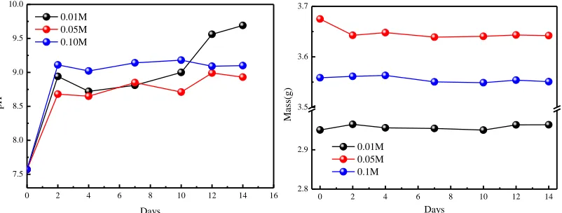
The biodegradability of MAO-coated samples was evaluated through immersion tests in vitro, conducted in SBF at 37°C for 14 d. The results showed that the weight loss and pH changed with immersion time for MAO-coated samples prepared in different KOH concentration (Fig. 8), while mass loss did not change significantly with immersion time. For pH versus time curves, all MAO-coated samples exhibited increased pH with increased immersion time.
0 2 4 6 8 10 12 14 16 7.5 8.0 8.5 9.0 9.5 10.0 pH Days 0.01M 0.05M 0.10M
0 2 4 6 8 10 12 14 2.8 2.9 3.5 3.6 3.7 Ma ss(g) Days 0.01M 0.05M 0.1M
Figure 8. Immersion test results of the MAO coatings prepared in different KOH concentrations: pH (left) and mass values (right)
[image:9.596.102.503.519.671.2]
caused magnesium hydroxide deposition. Then, deposition covered the sample surface and hindered continued corrosion by corrosive ions, but the magnesium hydroxide amounts were not very large. With infiltration of corrosive SBF, pores in a coating’s outer porous layer slowly expanded, such that the SBF entered the outer pores to the coating’s inner dense layer, thus reaching the interface between the substrate and dense layer. However, a long time was needed to infiltrate to the interface from the outer surface layer, which was explained by the protective effect of MAO coatings on the alloy coming mainly from the inner dense layer. At the same time, calcium phosphates began to deposit in large quantities, eventually stabilizing the pH.
4. CONCLUSION
Different MAO coatings were fabricated on ZK60 magnesium alloys in phosphate-borate electrolyte with different KOH concentrations. XRD results indicated that only the MgO phase without any other impurities existed in all MAO coatings. The KOH concentration had great influence on coating surface morphologies and the corrosion current density of MAO-coated alloys decreased about one order of magnitude more than that of than untreated substrates. The MAO-coated sample treated in 0.05 M KOH showed a relatively high self-corrosion potential, highest polarization resistance, lowest corrosion current density, and low corrosion rate, indicating the best corrosion resistance among all samples. The results from immersion tests also suggested that MAO coatings obtained in 0.05 M KOH displayed superior corrosion resistance in SBF in vitro. This good corrosion in vitro was mainly ascribed to the good surface quality of these MAO coatings.
ACKNOWLEDGMENTS
This study was supported by the National Natural Science Foundation of China (Grant No. 51471120) and Fundamental Research Funds for the Central Universities (No. 22120170200).
References
1. S. Virtanen, Mater. Sci. Eng. B, 176 (2011) 1600.
2. M. Laleh, A. S. Rouhaghdam, T. Shahrabi, A. Shanghi, J. Alloys Compd., 496 (2010) 548. 3. S. L. Aktu, S. Durdu, I. Kutbay, M. Usta, Ceram. Int., 42 (2015) 1246.
4. S. Agarwal, J. Curtin, B. Duffy, & S. Jaiswal, Materials Science and Engineering C, 68 (2016) 948.
5. K. Xia, H. Pan, T. Wang, S. Ma, J. Niu, Z. Xiang, Y. Song, H. Yang, X. Tang, W. Lu, Materials Science and Engineering C, 72 (2017) 676.
6. H. Yang, K. Xia, T. Wang, J. Niu, Y. Song, Z. Xiong, K. Zheng, S. Wei, W. Lu, J. Alloys Compd., 672 (2016) 366.
7. A. Atrens, G. Song, M. Liu, Z. Shi, F. Cao, and M. S. Dargusch, Adv. Eng. Mater., 17 (2015) 400. 8. U. Malayoglu, K. C. Tekin, S. Shrestha, Surf. Coat. Technol., 205 (2010) 1793.
9. Z. P. Yao, L. L. Li, X. R. Liu, Z. H. Jiang, Surf. Eng., 26 (2010) 317. 10.X. G. Han, X. P. Zhu, M. K. Lei, Surf. Coat. Technol., 206 (2011) 874.
6116.
12.R. F. Zhang, D. Y. Shan, R. S. Chen, E. H. Han, Materials Chemistry and Physics 107 (2008) 356. 13.Z. Li, Y. Yuan, X. Jing, Journal of Alloys and Compounds, 541 (2012) 380.
14.V. Ezhilselvi, J. Nithin, J.N. Balaraju, S. Subramanian, Surface & Coatings Technology, 288 (2016) 221.
15.R. F. Zhang, S. F. Zhang, J. H. Xiang, L. H. Zhang, Y. Q. Zhang, S. B. Guo, Surf. Coat. Technol., 206 (2012) 5072.
16.L. R. Krishna, G. Poshal, G. Sundararajan, Metal. Mater. Trans. A, 41 (2010) 3499. 17.R.F. Zhang, G.Y. Xiong, C.Y. Hu, Curr. Appl. Phys., 10 (2010) 255.
18.S. Q. Wang, F. Q. Xie, X. Q. Wu, Materials Chemistry and Physics, 202 (2017) 114. 19.D. Salih, K. Kemal, S.L. Aktuğ, A. Çakır, Surface & Coatings Technology, 326 (2017) 111. 20.S. X. He, Y. L. Ma, H. Yeb , X. D. Liu, Z. Y. Dou, Q. D. Xu, H. J. Wang, P. C. Zhang, Corrosion
Science, 122 (2017) 108.
21.F. Simchen, M. Sieber, T. Lampke, Surface & Coatings Technology, 315 (2017) 205.
22.A. Ghasemi, V. S. Raja, C. Blawert, W. Dietzel, & K. U. Kainer, Surf. Coat. Technol., 204 (2010) 1469.
23.J. Dou, G. Gu, C. Chen and Y. Pan, RSC Adv., 994 (2016) 104808.
24.L. Li, T. S. N. Sankara Narayanan, Y. K. Kim, J. Y. Kang, I. S. Park, T. S. Bae & M. H. Lee, Surf. Interface Anal., 46 (2014) 7.
25.H. X. Li, V. S. Rudnev, X. H. Zheng, T. P. Yarovaya and R. G. Song, J. Alloys Compd., 462 (2008) 99
26.Y. G. Ko, S. Namgung, D. H. Shin, Surf. Coat. Technol., 205 (2010) 2525
27.Y. L. Cheng, T. W. Qin, L. L. Li, H. M. Wang, Z. Zhang, Corros. Eng. Sci. Technol., 46 (2011) 17 28.A. Seyfoori, S. Mirdamadi, A. Khavandi, Z. S. Raufi, Appl. Surf. Sci., 261 (2012) 92.
29.S. Durdu, M. Usta, Appl. Surf. Sci., 261 (2012) 774.
30.S. Yagi, A. Sengoku, K. Kubota, E. Matsubara, Corros. Sci., 57 (2012) 74. 31.J. Liang, P. B. Srinivasan, C. Blawert, W. Dietzel, Corros. Sci., 51 (2009) 2483. 32.K. M. Lee, Y. G. Ko, D. H. Shin, J. Alloys Compd., 615 (2014) S418.
33.R. F. Zhang, S. F. Zhang, Y. L. Shen, L. H. Zhang, T. Z. Liu, Y. Q. Zhang, S. B. Guo, Appl. Surf. Sci., 258 (2012) 6602.
34.F. Liu, J. L. Xu, F. P. Wang, L. C. Zhao and T. D. Shimizu, Surf. Coat. Technol., 204 (2010) 3294. 35.S. B. Guo, Y. Q. Zhang, R. F. Zhang, S. F. Zhang, H. H. Zhang, Mater. Chem. Phys., 141 (2013)
121.
36.J. Liang, P. B. Srinivasan, C. Blawert, M. Störmer, W. Dietzel, Appl. Surf. Sci., 255 (2009) 4212. 37.M. Stern, A. L. Geary, J. Electrochem. Soc., 104 (1957) 56.
38.Y. Gu, C.-f. Chen, S. Bandopadhyay, C. Ning, Y. Zhang, Y. Guo, Appl. Surf. Sci., 258 (2012) 6116.
39.L. Pezzato, K. Brunelli, E. Napolitani, M. Magrini, M. Dabalà, Appl. Surf. Sci., 357 (2015) 1031. 40.F. Muhaffel, F. Mert, H. Cimenoglu, D. Höche, M. L. Zheludkevich, C. Blawer, Surf. Coat.
Technol., 269 (2015) 200.