Int. J. Electrochem. Sci., 14 (2019) 3455 – 3464, doi: 10.20964/2019.04.22
International Journal of
ELECTROCHEMICAL
SCIENCE
www.electrochemsci.orgShort Communication
Facile Synthesis of Nano-Si Modified Graphite Composite as
Anode Material for Lithium Ion Batteries
Hou Jiao1, Gong Bo-Lin1,*, Hou Chun-Ping2,3, Wang Bei-Ping2, Yang Dan3, Wang Xing-Wei3 1 College of Chemistry and Chemical Engineering, North Minzu University, Yinchuan Ningxia, 750021, P.R. China
2 College of Materials Science and Engineering, North Minzu University, Yinchuan Ningxia, 750021, P.R. China
3Ningxia BOLT Technologies Co., Ltd., Yinchuan Ningxia, 750002, P.R. China *E-mail: gongbolin@163.com
Received: 7 December 2018 / Accepted: 10 January 2019 / Published: 10 March 2019
We used a liquid-phase method to prepare a novel high capacity nano-Si modified graphite composite electrode material for lithium ion batteries. In this method, nano-Si powder was deposited onto the surface of natural spherical graphite using wet ball milling. CMC in solution was used as a binder between nano-Si and graphite and acted as a C coating in the sintering process. The acquired nano-Si modified graphite composite was investigated using X-ray diffraction (XRD), scanning electron microscopy (SEM). Electrochemical tests showed that the C coated nano-Si modified graphite composite had good electrochemical properties, such as high specific capacity, good rate capability and cycling performance and therefore was suitable for use in power or energy storage batteries. The 5 wt% nano-Si sample had a high specific capacity of 464.8 mAh g-1 at 0.1 C rate, which was approximately 87.37 % of the theoretical specific capacity (~532 mAh g-1).
Keywords: Nano-Si powder; Natural graphite; Composite; Liquid-phase; Carbon coating
1. INTRODUCTION
other metals, such as Sb and Sn, which can form a Li alloy during charging and release Li ions during discharging, were used as next generation anode materials. Among these materials, Si has a high theoretical capacity of 3579 mAh g-1 at room temperature, and has a Li:Si stoichiometry of 3.75:1(Li15Si4) which is approximately ten times the amount of Li in commercial graphite. Despite this, Si’s shortcomings, including poor rate capability, large volume expansion, rapid capacity fading and low coulombic efficiency, have become problems which need to be addressed before Si-based anodes are used in mass production and application. Unlike the traditional intercalation graphite electrode, Si and Li react via an alloying process, which results in significant volume expansion (approximately 300%) in the alloyed material. The change in concentration associated with the volume expansion results in significant mechanical stress within the electrode structure resulting in grain fractures and electrical isolation of the active material. During the process of alloying and de-alloying, large volume expansion/contraction of Si structures can result in an unstable solid-electrolyte-interphase (SEI) growth, which increases the ionic resistance and causes disintegration of the electrode. Moreover, the low coulombic efficiency of Si anodes during the first cycle is related to a volume change due to electronic contact loss by phase transformation and the formation of a SEI layer. To address these problems, efforts have been made to reduce volume expansion and contraction, as well as irreversible capacity of the Si anode.
2. EXPERIMENTAL
2.1. Preparation of nano-Si modified graphite composite anode material
Unless otherwise stated, all reagents are commercially available and used as prescribed. Nano-Si powders prepared using CVD method, were approximately 100 nm in diameter and had a Nano-Si content of 99.9 wt%. Spherical natural graphite (SNG) with a diameter of approximately 17 μm and a carbon content of 99.95 % was supplied by Ningxia BOLT technologies Co., Ltd. The preparation process was as follows. Firstly, 5.0 g of nano-Si powder was placed in a well-dispersed in 1.0 wt% CMC solution and stirred for 10 minutes. Then, 95.0 g of SNG was dispersed in the above-mentioned solution and milled for 30 minutes. The mixed slurry was then transferred into a beaker and dried in a 80℃ water bath while being continuously stirred. The prepared precursor was ground and mixed with 8.0 g of high temperature pitch until it was completely uniform. Finally, the prepared mixture was carbonized at 300℃ and 700℃ under a pure N2 atmosphere, and then was ground to 200 mesh size for testing.
2.2. Characterization
The synthesized nano-Si modified graphite composite anode material was characterised using a XRD-7000S diffractometer (Shimadza, Japan) with Cu Ka radiation (λ=0.15423 nm). The surface morphology of the nano-Si and its composite were observed using a scanning electronic microscope (Zeiss MERLIN Compact, Germany) with an Inca X-act EDS analyser (Oxford Instruments, UK). The phase composition of the material was determined using a Kratos Axis Ultra DDL X-ray spectrometer (Shimadza, Japan).
2.3. Electrochemical measurements
3. RESULTS AND DISCUSSION
[image:4.596.142.402.162.363.2]3.1 The crystalline forms and morphologies
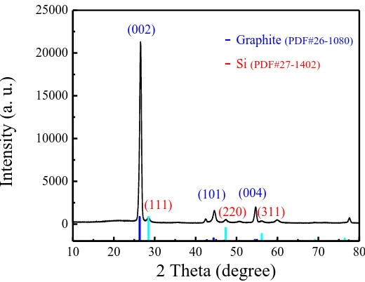
Figure 1. XRD patterns of the prepared nano-Si modified graphite composite.
The prepared nano-Si modified graphite composite contained both nano-Si and graphite (Fig. 1). The main diffraction peaks for graphite were situated at approximately 26.5º, 44.5º, and 54.6º, which was consistent with the (002), (101) and (004) lattice planes, respectively, and were indexed as the hexagonal structure of hexagonal graphite (PDF Card No. 26-1080). This result was in agreement with the literature [35]. The other main diffraction peaks for Si were consistent with the (111), (220) and (311) lattice planes, respectively, and were indexed as the crystalline silicon (PDF Card No. 27-1402). It can be seen from the XRD patterns that the preparation process had a role in the physical mixing but no influence on the crystalline forms of Si and SNG. However, the CMC and pitch which were used as the binder and coating layer, respectively, became amorphous C and increased the electrical conductivity of the prepared composite after carbonising at 700℃. Furthermore, we did not find impurity peaks corresponding to si-related compounds in the XRD pattern of the sample.
A B
10 20 30 40 50 60 70 80
0 5000 10000 15000 20000 25000
(311) (220) (111)
(004) (101)
Inten
sity
(a.
u.)
2 Theta (degree) (002)
- Graphite
(PDF#26-1080)
Figure 2. SEM images of the nano-Si (A), SNG (B) and prepared nano-Si modified graphite composite (C).
The morphologies of the nano-Si (A), SNG (B) and prepared nano-Si modified graphite composite (C) are shown in Fig. 2. The SEM image of the nano-Si as a raw material show the nano Si had a spherical morphology with a particle size of approximately 100 nm in diameter. SEM image (B) shows a near spherical morphology and numerous flakes were seen on the surface of SNG. When carbonising after nano-Si dispersion and pitch coating, the nano Si particles intersperse onto the surface of SNG, and appear a large number of bright conglomerations of Si-particles, which was confirmed to be elemental Si using XRD and XPS testing (Fig. 2).
0 200 400 600 800 1000 1200
0.0 2.0x10⁴ 4.0x10⁴ 6.0x10⁴ 8.0x10⁴ 1.0x10⁵
Si 2p
O1s
Intensit
y (
cps)
Binding Energy (eV) C1s
[image:5.596.189.405.69.227.2] [image:5.596.168.400.444.619.2]
Table 1. Elemental weight percentages (wt%) and atom (%) for boxed area in Figure 2 (C).
Element Element wt% Atom %
C 93.38 96.51
O 1.67 1.30
Si 4.95 2.19
Total 100.00 100.00
Fig. 3 shows XPS spectrum of the prepared nano-Si modified graphite composite. The main peaks for the sample were indexed as elemental Si, C and O, respectively. The C peak was very strong and sharp due to the perfect crystalline graphite, pyrolytic carbon from the pitch and CMC and their large percentage composition. The peaks of Si and O were less strong due to their lower percentage. Furthermore, the EDS analysis for the boxed area in Fig. 2 (C) demonstrated that the surface area contained 96.51 atom % of C, 1.30 atom % of O and 2.19 atom % of Si (Table 1). The generation of oxygen could be a result of the oxidation of Si with trace oxygen during the preparation and carbonization process.
3.2 Electrochemical measurements
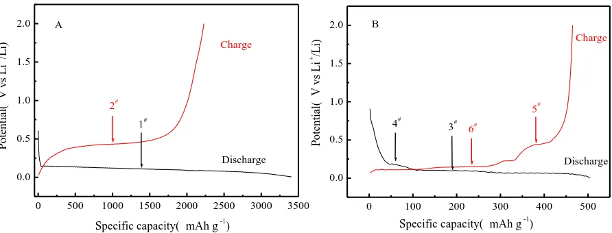
Figure 4. Potential profiles of the nano-Si (A) and prepared nano-Si modified graphite composite (B) in the first cycle at a rate of 0.1 C at room temperature.
Fig. 4 (A) shows the first potential-capacity profiles of the nano-Si anode, which were determined at 0.1 C and voltage ranging from 0.03 to 2.00 V (vs. Li+/Li). The curves show typical lithiation (1#) and delithiation (2#) plateaus of Si at approximately 0.10 and 0.45 V, respectively, in agreement with the literature [18,36]. The initial discharge and charge capacities were 3406.5 and 2227.7 mAh g-1 for the nano Si anode, which corresponded to an initial coulombic efficiency of 65.4 %. In general, the low initial coulombic efficiency was possibly due to the formation of a SEI layer, the irreversible reaction
0 500 1000 1500 2000 2500 3000 3500 0.0 0.5 1.0 1.5 2.0 2# 1# Discharge Charge A P o te n ti al ( V v s L i + /L i)
Specific capacity( mAh g-1)
0 100 200 300 400 500
0.0 0.5 1.0 1.5 2.0 6# 3#
Specific capacity( mAh g-1)
[image:6.596.71.517.438.608.2]
between Li and Si host material, and the poor conductivity of the nano Si. However, the potential-capacity curves of the prepared nano-Si modified graphite composite shows two lithiation plateaus (3# and 4#) and two delithiation plateaus (5# and 6#), which corresponded to Li intercalation of graphite and lithiation of Si in the discharge process, as well as Li deintercalation of graphite and delithiation of Si in the charge process (Fig. 4 (B)). This demonstrates that there were two reactions occurring in the charge and discharge processes. In comparison, the initial discharge and charge capacities of the nano-Si modified graphite composite were 505.4 and 464.8 mAh g-1, respectively, having a coulombic efficiency of 92.0%. Hence, the coulombic efficiency of the nano-Si modified graphite composite was much greater than that of Si nanoparticles, which could be due to the formation of conductive pyrolytic carbon from the coating pitch and CMC, as well as graphite’s intrinsic conductivity. The pyrolytic carbon and graphite had close electrical contact with the nano Si particles.
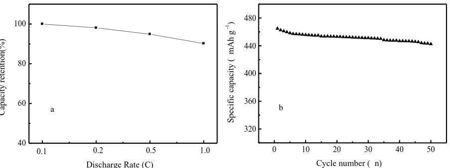
Figure 5. The capacity retention of the prepared nano-Si modified graphite composite electrode at different rates (a) and the cycling performance of the prepared sample at a rate of 0.1 C (b).
Due to poor conductivity and electrochemical properties, the pure nano-Si anode material cannot be used in practical industrial production. In this study, the electrochemical properties of the prepared nano-Si modified graphite composite and synergetic effect between nano Si and graphite, as well as conductive C coating, were investigated. Fig. 5 shows the rate capability and cycling performance of the prepared nano-Si modified graphite composite electrode. The nano-Si/graphite composite electrode had an excellent rate capability. The sample delivered a specific capacity of 419.2 mAh g-1 at a rate of 1.0 C, which was approximately 90.2% of that at 0.1 C. The excellent rate capability could be due to the enhanced electro-conductivity of the pyrolytic carbon coating layer and fast Li-ion transportation due to form a C/graphite conductive network, which reduced the inner resistance of the prepared anode [37].
In addition, other factors such as cycling performance and low-temperature characteristics are important and should be considered to meet the requirements of EV, 3 C products or smart grids systems. In Fig. 5(b), the prepared nano-Si modified graphite composite electrode had a good capacity retention ratio. After 50 cycles, the sample had a high specific capacity of 442.5 mAh g-1, corresponding to a
40 60 80 100 a 1.0 0.5 0.2 0.1 C ap ac it y r et en ti o n (% )
Discharge Rate (C)
0 10 20 30 40 50
320 360 400 440 480 b S p ec if ic c ap ac it y ( m A h g -1 )
[image:7.596.78.530.298.467.2][image:8.596.100.490.150.304.2]
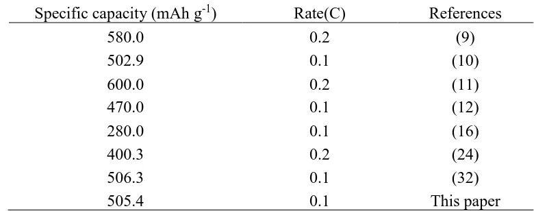
capacity retention ratio of 95.2%, due to form a conducting layer on Si nanoparticle and construct a conductive network on the surface of the SNG and nano-Si through the core-shell structure [38]. Table 2. Specific capacities of similar composite anode materials prepared by different methods
Specific capacity (mAh g-1) Rate(C) References
580.0 0.2 (9)
502.9 0.1 (10)
600.0 0.2 (11)
470.0 0.1 (12)
280.0 0.1 (16)
400.3 0.2 (24)
506.3 0.1 (32)
505.4 0.1 This paper
Compared to the similar lithium anode electrode materials which were described in literature, the as-prepared nano-Si modified graphite composite by a liquid-phase method has better reversible capacity and cycling performance than those prepared by complex process.
4. CONCLUSIONS
In this study, a liquid-phase method was used to prepare a novel high capacity nano-Si modified graphite composite anode material. Nano-Si powder was deposited onto the surface of a spherical natural graphite using wet ball milling, and then coated using high-temperature pitch to form a hybrid conductive network. The uncoated nano Si electrode had a high initial specific capacity of 2227.7 mAh g-1, but a low initial coulombic efficiency of 65.4%. The prepared nano-Si modified graphite electrode delivered an acceptable specific capacity and exhibited better rate capability and cycling performance due to the superior electronic conductivity achieved by C coating and synergetic effects of graphite. The 5 wt% nano-Si sample had a high specific capacity of 464.8 mAh g-1 at a rate of 0.1 C, which was approximately 87.4% of the theoretical specific capacity, a capacity retention ratio of 90.2% at 0.1 C/1.0 C and a capacity retention ratio of 95.2% after 50 cycles. Therefore, C coating and graphite recombination are possible methods for the application of nano-Si anode material in power or energy storage batteries. Compared with other similar materials, nano-Si modified graphite composite we prepared has better reversible capacity and cycling performance.
ACKNOWLEDGEMENTS
References
1. J.M. Tarascon, M. Armand, Nature, 414 (2001) 359-367.
2. J.B. Goodenough, Y. Kim, Chemistry of Materials, 22 (2010) 587-603. 3. L. Shen, H. Li, E. Uchaker, X. Zhang, G. Cao, Nano Letters, 12 (2012) 1-6. 4. K. Saravanan, N. Kalaiselvi, Carbon, 81 (2015) 43-53.
5. N.C. Gallego, C.I. Contescu, H.M. Meyer, J.Y. Howe, R.a. Meisner, E.A. Payzant, M.J. Lance, S.Y. Yoon, M. Denlinger, D.L. Wood, Carbon, 72 (2014) 393-401.
6. Z.S. Wen, J. Yang, B.F. Wang, K. Wang, Y. Liu, Electrochemistry Communications, 5 (2003) 165-168.
7. S. Li, X. Qin, H. Zhang, J. Wu, Y.-B. He, B. Li, F. Kang, Electrochemistry Communications, 49 (2014) 98-102.
8. B.C. Yu, Y. Hwa, J.H. Kim, H.J. Sohn, Electrochemistry Communications, 46 (2014) 144-147. 9. S.Y.Kim, J.Lee, B-H.Kim, Y-J.Kim, K.S.Yang, M-S.Park, ACS Applied Materials & Interfaces, 8
(2016) 12109−12117.
10.M. Su, Z. Wang, H. Guo, X. Li, S. Huang, L. Gan, W.Xiao, Powder Technology, 249 (2013) 105-109.
11.Y. Wang, S. Chou, J. H. Kim, H. Liu, S. Dou, Electrochimica Acta ,93 (2013) 213-221. 12.S.Kim. N.A. Dunlap, J. J. Jeong, K. H. Oh, S-H. Lee, Solid State Ionics , 324 (2018) 207-217 13.S.-H. Ng, J. Wang, D. Wexler, K. Konstantinov, Z.-P. Guo, H.-K. Liu, Angewandte Chemie
International Edition, 45 (2006) 6896-6899.
14.M.T. McDowell, I. Ryu, S.W. Lee, C. Wang, W.D. Nix, Y. Cui, Advanced Materials, 24 (2012) 6034-6041.
15.M.L. Mastronardi, E.J. Henderson, D.P. Puzzo, G.a. Ozin, Advanced Materials, 24 (2012) 5890-5898.
16.Q. Zhao, Y.Hang, X. Hu , Electrochemistry Communications, 70 (2016) 8-12.
17.U. Kasavajjula, C. Wang, a.J. Appleby, Journal of Power Sources, 163 (2007) 1003-1039. 18.M.-S. Wang, W.-L. Song, J. Wang, L.-Z. Fan, Carbon, 82 (2015) 337-345.
19.H. Kim, B. Han, J. Choo, J. Cho, Angewandte Chemie International Edition, 47 (2008) 10151-10154.
20.D.M. Piper, J.H. Woo, S.B. Son, S.C. Kim, K.H. Oh, S.H. Lee, Advanced Materials, 26 (2014) 3520-3525.
21.R. Zhang, Y. Du, D. Li, D. Shen, J. Yang, Z. Guo, H.K. Liu, A.a. Elzatahry, D. Zhao, Advanced materials (Deerfield Beach, Fla.), (2014) 6749-6755.
22.J. Xie, X. Yang, S. Zhou, D. Wang, ACS Nano, 5 (2011) 9225-9231.
23.L. Baggetto, D. Danilov, P.H.L. Notten, Advanced Materials, 23 (2011) 1563-1566. 24.H.Zhang, X.Li, H. Guo, Z.Wang, Y. Zhou, Powder Technology , 299 (2016) 174-184. 25.H. Xiang, K. Zhang, G. Ji, J.Y. Lee, C. Zou, X. Chen, J. Wu, Carbon, 49 (2011) 1787-1796. 26.J. Ji, H. Ji, L.L. Zhang, X. Zhao, X. Bai, X. Fan, F. Zhang, R.S. Ruoff, Advanced Materials, 25
(2013) 4673-4677.
27.A. Gohier, B. Laïk, K.H. Kim, J.L. Maurice, J-Pierre, P-Ramos, C. S. Cojocaru , P. T. Van Advanced Materials, 24(2012) 2592-2597.
28.F. Yao, B. Li, K. So, J. Chang, T.H. Ly, A.Q. Vu, H. Mun, C.S. Cojocaru, H. Yue, S. Xie, Y.H. Lee, Carbon, 79 (2014) 563-571.
29.F. Zhang, X. Yang, Y. Xie, N. Yi, Y. Huang, Y. Chen, Carbon, 82 (2015) 161-167.
30.V.a. Sethuraman, K. Kowolik, V. Srinivasan, Journal of Power Sources, 196 (2011) 393-398. 31.F.-f. Cao, J.-w. Deng, S. Xin, H.-x. Ji, O.G. Schmidt, L.-j. Wan, Advanced Materials, 23 (2011)
4415-4420.
33.M.-H. Ryou, J. Kim, I. Lee, S. Kim, Y.K. Jeong, S. Hong, J.H. Ryu, T.-S. Kim, J.-K. Park, H. Lee, J.W. Choi, Advanced Materials, 25 (2013) 1571-1576.
34.B. Koo, H. Kim, Y. Cho, K.T. Lee, N.-S. Choi, J. Cho, Angewandte Chemie International Edition, 51 (2012) 8762-8767.
35.X. He, D. Hubble, R. Calzada, A. Ashtamkar, D. Bhatia, S. Cartagena, P. Mukherjee, H. Liang, Journal of Power Sources, 275 (2015) 688-693.
36.N. Lin, Y. Han, J. Zhou, K. Zhang, T. Xu, Y. Zhu, Y. Qian, Energy & Environmental Science, 8 (2015) 3187-3191.
37.F. Zhou, K. Qiu, G. Peng, L. Xia, Electrochimica Acta, 151 (2015) 16-20.
38.C. Hou, H. Zhang, Y. Ma, W. Geng, Q. Zhang, Int. J. Electrochem. Sci., 12 (2017) 3652-3661.