Int. J. Electrochem. Sci., 12 (2017) 7457 – 7468, doi: 10.20964/2017.08.55
International Journal of
ELECTROCHEMICAL
SCIENCE
www.electrochemsci.org
Xanthan Gum as a Potential Binder for Graphite Anode in
Lithium-Ion Batteries
Zhaoqing Wang1, Guoju Dang1,2, Quansheng Zhang1,*, Jingying Xie2,3,*
1
Department of Chemical Engineering, Shanghai Institute of Technology, Shanghai 200235, China
2
Shanghai Institute of Space Power Sources, Shanghai 200245, China
3
Shanghai Power & Energy Storage Battery System Engineering Tech. Co. Ltd., Shanghai 200240, China
*
E-mail: [email protected], [email protected]
Received: 14 May 2017 / Accepted: 18 June 2017 / Published: 12 July 2017
As an important component of the electrode, the choice of appropriate and favorable binder is significant for fabricating lithium-ion (Li-ion) batteries with good cycle stability and C-rates capacity, which are implemented for numerous applications especially in portable electronics and eco-friendly electric vehicles (EV). In this work, xanthan gum was used as binder for graphite anode, the adhesive strength of the active materials to the current collector was investigated by scratch test. The results confirmed that the xanthan gum (XG) had a better bonding performance with copper (Cu) foil than poly (vinylidene fluoride) (PVDF), as well as XG had a larger plastic deformation resistance than the PVDF. Electrochemical impedance spectroscopy (EIS) measurement demonstrated that the graphite electrode using XG as binder has lower charge transfer resistance and more active kinetics on the electrode/electrolyte surface. All the electrochemical performance tests indicated that XG binder for graphite anode in Li-ion battery had a better cycling and rate performance than PVDF binder for graphite anode in Li-ion battery.
Keywords: scratch test, xanthan gum, electrochemical performance, graphite anode, Li-ion battery.
1. INTRODUCTION
also can alleviate the swell of active particles attributed to the lithium-ion insert/deinsert into the active material layers. As is known to all, poly (vinylidene fluoride) (PVDF) has been a conventional binder because of good binding capacity, electrochemical stability and ability to absorb electrolyte [4-6]. However, more and more water-soluble binders are investigated to replace the PVDF binder since the water-soluble binder system is cheaper and more eco-friendly, as well as the Li-ion batteries fabricated with water-soluble binder show higher initial columbic efficiency, better cycle stability and C-rates capacity, e.g. sodium carboxymethyl cellulose (CMC), styrene butadiene rubber (SBR) and their mixture [7-9], CMC-formate [10], alginate [11], poly (acrylicacid-acrylonitrile-butylacrylate)-polystyrene [12], polyacrylic acid (PAA) [13], polyvinyl alcohol (PVA) [14], poly vinyl acetate (PVAc) [15], polyethylene mine (PEI) [16], polyimide (PI) [17], chitosan [18], polymerized vinylene carbonate (polyVC) [19], guar gum (GG) [20, 21]. It is important to find why the water-based Li-ion batteries show better electrochemical performance than PVDF-based Li-ion batteries.
and the EIS test shown the good electronic and ionic conductivity of graphite anode with XG binder, we prove that the electrochemical performance of graphite anode can be significantly improved with XG as a novel binder.
2. EXPERIMENTAL
2.1. Materials
Natural graphite (NG, Sinopharm Chemical Reagent Co., Ltd) was applied as the electrode active material. Acetylene black (AB) was used as the conductive additives, which was obtained from TIMCAL.XG, dispersed into deionized water with a concentration of 1wt% and purchased from Deosen Biochemical Ltd., was used as the binder. For comparison, PVDF (900,Arkema) binder was dissolved into NMP (Sinopharm Chemical Reagent Co., Ltd) with a concentration of 8 wt%. The electrolyte was 1.2M LiPF6 in ethylene carbonate/ethyl methyl carbonate (EC/EMC, 1:1, v/v) supplied
from Zhang jiagang Guotai-Huarong New Chemical Materials Co., Ltd..
2.2. Mechanical scratch test study
The adhesion between the binders and copper (Cu) foil current collector was investigated by a micro-scratch test on CETR UMT multi-functional tribometer at room temperature and 50-60% humidity, with a diamond tip used as the counterpart. The XG and PVDF binders’ solutions were coated equably on the Cu foil with a doctor-blade (thickness 200um). After drying, these films were cut into specimens with an area of 1cm×2cm. The indenter scratched over the coating surface under a preload with 0.05N for 5s, and then a linear load from 0.05N to 5N at a constant sliding speed of 0.04mm/s and the total slide distance was 8mm. All the surface morphologies of PVDF/Cu (Cu substrate of PVDF based coating) and XG/Cu (Cu substrate of XG based coating) coatings after wear tests were observed by scanning electron microscopy (SEM, Hitachi S-3400N, 15kV).
2.3. Electrode preparation
2.3. Electrode characterization
Cyclic voltammetry (CV) and Electrochemical impedance spectroscopy (EIS) measurements were performed using an electrochemical workstation at the room temperature. The cyclic voltammograms were measured at the scan rate of 0.1mV·s-1 between the potential of 0.0V and 2.0V (vs. Li/Li+). The EIS spectra were recorded in the frequency range from 10-2 to 105 Hz after different cycling stages.
The charge-discharge cycle tests and rate tests were performed with a battery charging-discharging instrument (from Wuhan LAND electronics Co., Ltd.) between 0.5mV and 2.0V (vs. Li/Li+) at the room temperature. The cycle tests were carried out with a constant current of 0.5C (1C=372mAh g-1). And the cells were charged (intercalation) at 0.2C and discharged (deintercalation) at different C-rates.
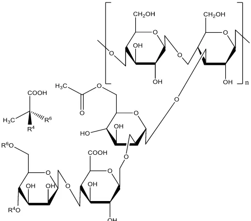
Figure 1. The molecular structure of xanthan gum polymer.
3. RESULTS AND DISCUSSION
[image:4.596.169.427.284.511.2]3.1. Scratch test experiment
[image:4.596.140.458.620.726.2]
Figure 3. Coefficient of friction (COF) versus time curves of PVDF/Cu (a) and XG/Cu (b) coatings by scratching with a preload of 0.05N for 5s and then a linear load from 0.05N to 5N at a constant sliding speed of 0.04mm/s.
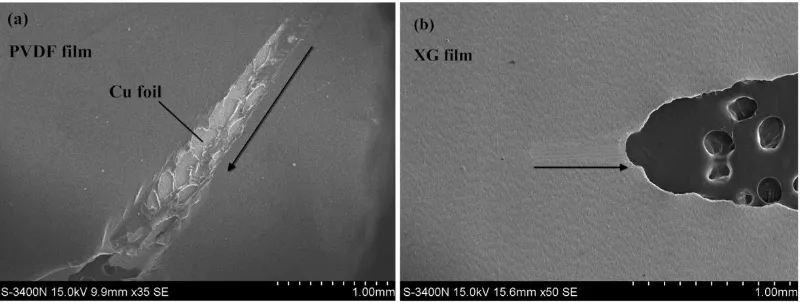
Figure 4. SEM images of the surface morphologies of PVDF/Cu (a) and XG/Cu (b) coatings after scratch tests;
[image:5.596.109.489.78.211.2] [image:5.596.99.499.290.441.2]
higher friction coefficient value than PVDF/Cu composite coating implies the XG binder polymer has a larger hardness than PVDF with a further indication that the XG polymer has a larger plastic deformation resistance, which illustrates that the deformation occurs harder on XG binder. And the one less mutation of COF versus time curve of XG/Cu coating specimen is attributed to better adhesion between XG binder and Cu foil substrate than PVDF/Cu coating. The good adhesion strength of XG binder may arise from its abundant functional groups such as carboxyl and hydroxyl, which are naturally present and evenly distributed along the polymer chain. These functional groups contribute to a larger numbers of possible active bonding sites among active material, conductive agent and current collector, facilitating electronic and ionic conducting and ensuring good dispersion during the slurry production and electrode fabrication process [44].
To understand the above mechanical performance, the surface morphologies of PVDF/Cu (a) and XG/Cu (b) coatings after scratch tests were obtained using SEM in Fig.4.a and Fig.4.b. The arrow direction displays the scratch direction. With the diamond tip touches the specimens under a constant preload of 0.05N for 5s, the surface of coatings produces little deformation and stress. Then the PVDF/Cu and XG/Cu specimens undergo different crack process along with the diamond tip scratches over the coatings surface at a linear load from 0.05N to 5N. The crack process of the former included the elasto-plastic deformation of PVDF film, the incomplete crack and complete crack of PVDF film, finally the crack of Cu foil substrate, while the latter contained the elasto-plastic deformation of XG film, then the together crack of XG/Cu coating. It is clearly to see that the XG film doesn’t crack when the diamond tip scratches over the coating surface, just with a scratch mark, which also demonstrate that the XG binder has a larger plastic deformation resistance than the PVDF binder as mentioned above.
3.2. Electrochemical performance
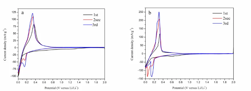
Figure 5. Cyclic voltammograms of the graphite anode coated with XG (a) and PVDF (b) at the scan rate of 0.1mV·s-1 between the potential of 0.0V and 2.0V (vs. Li/Li+).
[image:6.596.82.521.506.666.2]
the irreversible capacity loss. By contrast, the XG-based graphite anode exhibits a reduction peak ranging from 1.5V to 0.6V in the first cycle. These results imply that the kinetics of SEI formation will be different for the different choices of binders, and some previous reports have demonstrated that hydroxyl group and carboxyl group are beneficial to the formation of the SEI film [14, 48]. The formation of SEI film on the surface of anodes could promote the stability during the long-term cycling and facilitate the lithium ion conductivity.
In the following reduction process, the peaks at around 0.15V,0.05V correspond to the process of lithium intercalation to the graphite interlayer (LixC6, x≤1). The oxidation peaks between 0.2V and
0.4V are related to the lithium de-intercalation from LixC6. The PVDF-based electrode provides a
[image:7.596.169.427.382.572.2]lithium de-insertion potential of about 0.32V, and the use of XG shifts slightly to about 0.36V. The tiny difference may be caused by the reason that XG prefers to be ionic conductor. Refer to one previous report [41], XG showed a little higher lithium de-insertion potential than PVDF as a binder using for the mesocarbon microbeads (MCMBs) anode, which proved that XG performed negative shifts of the lithium de-insertion as the cellulose-based binder is electronic insulators but expected to be ionically more conductive. The binder adds a physical barrier to lithium insertion/de-insertion, which makes the lithium ion movement process more difficult than in the bare binder, while which are still expected to enhance the electrode/electrolyte interface.
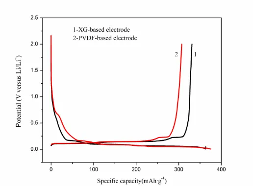
Figure 6. The first charge-discharge curves of the natural graphite electrodes fabricated with different binders between 0.5mV and 2.0V (vs. Li/Li+) at the room temperature.
[image:8.596.191.406.131.280.2]
characteristics in the first cycle, which demonstrates that the reductive decomposition of the electrolyte components on the electrode/electrolyte surface is weaker than the electrode with PVDF binder.
Figure 7. Discharge capacity of the natural graphite electrodes prepared with different binders at C/2 for 180 cycles between 5mV and 2V versus Li/Li+.
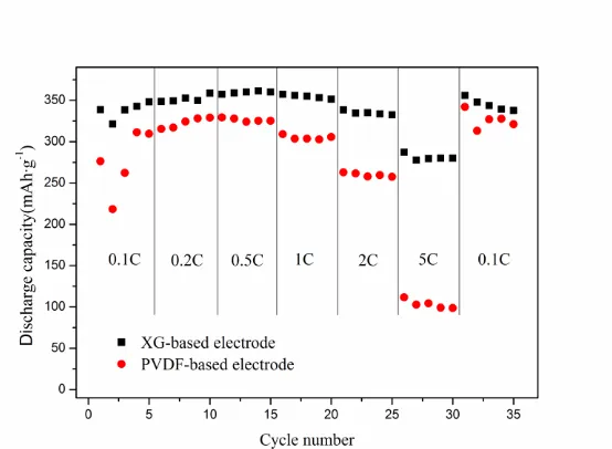
Figure 8. Rate capability of the natural graphite electrodes prepared with different binders, cycled between 5mV and 2V versus Li/Li+ at different C-rates C/10, C/5, C/2, C, 2C, 5C, C/10.
[image:8.596.161.438.354.557.2]
electrochemical cycles, which can be explained by the better adhesive between the XG binder and Cu foil as well as the larger plastic deformation resistance that XG binder presents a better ability to resist deformation to buffer the graphite volume expansion during the long-term charge-discharge cycle tests that conforms to the mechanical property in the above discussion.
Figure 9. Nyquist plots of graphite electrodes using XG and PVDF binder from 10-2 to 105 Hz at 100% DOD, (a) after 180 long-term cycles. (b) after different rates cycles (C/10, C/5, C/2, C, 2C, 5C, C/10). (c) the equivalent circuit used for the fitting of the EIS data.
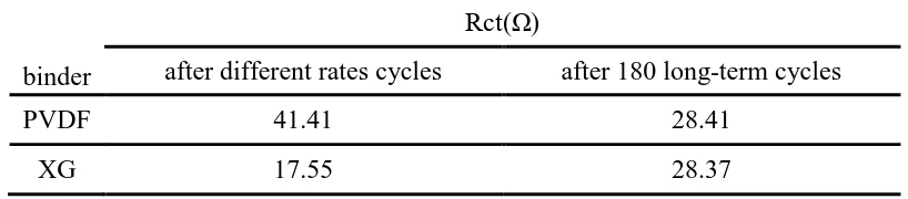
Table 1. Charge transfer resistance Rct for graphite with XG and PVDF binders.
binder
Rct(Ω)
after different rates cycles after 180 long-term cycles
PVDF 41.41 28.41
XG 17.55 28.37
The EIS technique has been an available tool for investigating the further electrode kinetics. Fig.9 displays the EIS of Li/graphite cell at 100% DOD after different cycling stages and an equivalent circuit used for modeling the spectrum. Definitely, the EIS consists of two semicircles. As discussed before [5, 49, 50], each semicircle can be fitted by an analogous equivalent circuit. Rs represents the resistance of the solution. The high-frequency semicircle is considered as the resistance (R1) of
passivating SEI film, and medium-frequency semicircle reflects the charge-transfer resistance (Rct) at the electrodes.C1 and CPE are the capacity and constant phase element associated with R1 and Rct,
[image:10.596.157.416.122.179.2] [image:10.596.93.502.287.377.2]
condition after different cycle stages. On the basis of these analyses, XG presents apparent advantages in fabricating high-performance anode compared with conventional PVDF binder.
4. CONCLUSIONS
The natural graphite electrode fabricated with XG binder presented a remarkable electrochemical performance. Compared with the conventional PVDF-based anode, the initial columbic efficiency, cycling stability and rate capability were substantially improved. The wear tests were not only to demonstrate that the XG film has a higher elasticity than the PVDF film, but also to prove that there is better adhesion strength between XG binder and Cu foil substrate than PVDF/Cu coating. EIS measurements manifested that the graphite electrode using XG as binder had lower charge transfer resistance and more active kinetics on the electrode/electrolyte surface than the electrode using PVDF binder. The present results indicate that the graphite electrode with XG as binder not only can reduce cost and environmental pollution, but also can enhance the electrochemical performance. All the test results are in accordance with the former study.
References
1. J. M. Tarascon, M. Armand, Nature, 414 (2001) 359.
2. M. Hu, X. L. Pang, Z. Zhou, J. Power Sources, 237 (2013) 229. 3. J. B. Goodenough, Y. Kim, Chem. Mater, 22 (2010) 587.
4. S. L. Chou, J. Z. Wang, H. K. Liu, S. X. Dou, J. Phys. Chem. C., 115 (2011) 16220.
5. Z. Fu, H. L. Feng, X. D. Xiang, M. M. Rao, W. Wu, J. C. Luo, T. T. Chen, Q. P. Hu, A. B. Feng, W. S. Li, J. Power Sources, 261 (2014) 170.
6. G. Liu, H. Zheng, A. S. Simens, A. M. Minor, X. Song, V. S. Battaglia, J. Electrochem. Soc.,154 (2007) A1129.
7. M. Mancini, F. Nobili, R. Tossici, R. Marassi, Electrochim. Acta, 85 (2012) 566. 8. J. Xu, S. L. Chou, Q. F. Gu, H. K. Liu, S. X. Dou, J. Power Sources, 5 (2013) 172. 9. Y. S. Park, E. S. Oh, S. M. Lee, J. Power Sources, 248 (2014) 1191.
10. L. Qiu, Z. Q. Shao, D. X. Wang, W. J. Wang, F. J. Wang, J. Q. Wang, Carbohyd. Polym., 111 (2014) 588.
11. J. T. Xu, S. L. Chou, Q. F. Gu, H. K. Liu, S. X. Dou, J. Power Sources, 225 (2013) 172. 12. M. H. T. Nguyen, E. S. Oh, J. Electroanal Chem., 739 (2015) 111.
13. J. Pan, G. Y. Xu, B. Ding, Z. Chang, A. X. Wang, H. Dou, X. G. Zhang, RSC Adv., 6 (2016) 40650
14. H. K. Park, B. S. Kong, E. S. Oh, Electrochem. Commun., 13 (2011) 1051.
15. P. P. Prosini, M. Carewska, C. Cento, A. Masci, Electrochim. Acta, 150 (2014) 129. 16. J. Bae, S. H. Cha, J. Park, Macromol Res., 21 (2013) 826.
17. J. S. Kim, W. Choi, K. Y. Cho, D. Byun, J. C. Lim, J. K. Lee, J. Power Sources, 244 (2013) 521. 18. L. L. Chai, Q. T. Qu, L. F. Zhang, M. Shen, L. Zhang, H. H. Zheng, Electrochim. Acta, 105 (2013)
378.
19. H. Zhao, X. Zhou, S. J. Park, F. F. Shi, Y. B. Fu, M. Ling, N. Yuca, V. S. Battaglia, G. Liu, J. Power Sources, 263 (2014) 288.
21. Q. Y. Li, H. J. Yang, L. S. Xie, J. Yang, Y. N. Nuli, J. L. Wang, Chem. Commun., 52 (2016) 13479. 22. M. Y. Wu, X. C. Xiao, N. Vukmirovic, S. D, Xun, P. K. Das, X. Y. Song, P. O. Velasco, D. D.
Wang, A. Z. Weber, L. W. Wang, V. S. Battaglia, W. L. Yang, G. Liu, J. Am. Chem. Soc., 135 (2013) 12048.
23. Q. F. Yuan, F. G. Zhao, Y. M. Zhao, Z. Y. Liang, D. L. Yan, J. Solid. State. Electrochem., 18 (2014) 2167.
24. L. B. Chen, X. H. Xie, J. Y. Xie, K. Wang, J. Yang, J. Al. Electrochem., 36 (2006) 1099.
25. M. H. Ryou, J. Kim, I. Lee, S. Kim, Y. K. Jeong, S. Hong, J. H. Ryu, T. S. Kim, J.K. Park, H. Lee, J. W. Choi, Adv. Mater, 25 (2013) 1571.
26. K. Krzysztof. J. Mater. Eng. Perform., 25(2016) 2326.
27. T. Yim, S. J. Choi, Y. N. Jo, T. H. Kim, K. J. Kim, G. Jeong, Y. Kim, Electrochim. Acta, 136 (2014) 112.
28. J. Yoon, D. X. Oh, C. Jo, J. Lee, D. S. Hwang, Phys. Chem. Chem. Phys., 16 (2014) 25628. 29. H. Zheng, R. Z. Yang, G. Liu, X. Y. Song, V. S. Battaglia, J. Phys. Chem. C, 116 (2012) 4875. 30. N. Yuca, H. Zhao, X. Y. Song, M. F. Dogdu, W. Yuan, Y. B. Fu, V. S. Battaglia, X. C. Xiao, G.
Liu, ACS Al. Mat. Interfaces, 6 (2014) 17111.
31. M. Ling, Y. N. Xu, H. Zhao, X. X. Gu, J. X. Qiu, S. Li, M. Y. Wu, X. Y. Song, C. Yan, G. Liu, S. Q. Zhang, Nano Energy, 12 (2015) 178.
32. M. Yoo, C. W. Frank, S. Mori, S. Yamaguchi, Polymer, 44 (2003) 4197. 33. S. Ramdon, B. Bhushan, J. Power Sources, 246 (2014) 219.
34. D. Dong, X. H. Chen, W. T. Xiao, G. B. Yang, P. Y. Zhang, Al. Surf Sci, 255 (2009) 7051. 35. P. F. Li, H. Zhou, X. H. Cheng, Al. Surf Sci, 285P (2013) 937.
36. M. Ö. Bora, Tribol. Int., 78 (2014) 75.
37. P. Kurkcu, L. Andena, A. Pavan, Wear, 317 (2014) 277.
38. H. K. Park, B. S. Kong, E. S. Oh, Electrochem. Commun., 13 (2011) 1051. 39. L. Y. Gong, M. H. T. Nguyen, E. S. Oh, Electrochem. Commun., 29 (2013) 45. 40. Z. Xue, Z. C. Zhang, K. Amine, Electrochem. Commun., 34 (2013) 86.
41. F. M. Courtel, S. Niketic, D. Duguay, Y. A. Lebdeh, I. J. Davidson, J. Power Sources, 196(2011) 2128.
42. N. Cuesta, A. Ramos, I. Cameán, C. Antuña, A. B. García, Electrochim. Acta, 155 (2015) 140. 43. D. Chen, R. Yi, S. R. Chen, T. Xu, M. L. Gordin, D, H. Wang, Solid State Ionics, 254 (2014) 65. 44. J. R. He, H. X. Zhong, J. L. Wang, L. Z. Zhang, J. Alloys Compd., 714 (2017) 409.
45. W. Haselrieder, B. Westphal, H. Bockholt, A. Diener, S. HÖft, A. Kwade, Int. J. Adhes. Adhes., 60 (2015) 1.
46. S. D. Beattie, D. Larcher, M. Morcrette, B. Simon, J. M. Tarascon, J. Electrochem. Soc., 155 (2008) A158.
47. D. Mazouzi, B. Lestriez, L. Roué, D. Guyomard, Electrochem. Solid. ST., 12 (2009) A215. 48. S. Komaba, N. Yabuuchi, T. Qzeki, K. Okushi, H. Yui, K. Konno, Y. Katayama, T. Miura, J.
Power Sources, 195(2010) 6069.