'I'
I
ROBUST AND ADAPTIVE
RECEIVER DESIGN FOR
WIRELESS COMMUNICATION
SYSTEMS
Zheng Li
BE, ME Electrical Engineering Shanghai J iao Tong Un i versi ty, China
Apr
il
2000
A thesis submitted for the degree of Master of Engineering
of the Australian National University
Department of Engineering
Declaration
The work contained in this thesis, except where explicitly stated, is original research performed by the author. This work has not been submitted for a degree at any other university or institution.
These studies were conducted under supervision of Dr. Lei Wei, Dr. Matthew James, and Dr'. Rodney Kennedy. Dr. Wei and Dr. James are with Depart-ment of' Engineering, Faculty of Engineering and Information Technology, The Australian National University. Dr. Kennedy is with Telecommunication Group, Research School of Information and System Engineering, The Australian National University.
Acknow ledgement
The author is fortunate to have Dr. Lei Wei, Dr. Matthew James and Dr. Rodney Kennedy as my supervisor aod advisors.
Dr. Wei introduced me into the field of telecommunication engineering in the beginning and spent great time explaining to me the basics of multiuser detection, Viterbi algorithm and error control coding. Most of my research work comes out of our frequent discussion and joint effort 00 numerous topics. lowe great thanks to Dr. Wei for his supervision.
Dr. James introduced me into the area of robust signal processing and con-tributed tremendously to the two robust related publication. I'm glad I can help him with the lab work of ENG:J3001 Digital Design. Dr. James also gave me lots of support in my career planning.
Dr. Kennedy gave me great support during my mid-term review and final thesis writing. And he is also kind enough to give me general advice on research and career planning.
I'd also like to thank Dr. Ian Petersen for his kind comments on my two robust related publication. Dr. Brian Hart gave me a valuable tutorial on fading channel. Dr. Predrag Rapajic gave me several interesting talks on adaptive filter design and practical communication channels.
The author want to thank Bob Edwards for his help resolving computing issues and the ladies of our department: Sue, Josephine and Sharon for administrative support.
lot from each and every of you almosL every day. I'll remember this experience. I'd also like Lo thank all the students I know in this department: Endra Julianto for his LaTeX tips and his wife's dinner, William Paul Malcolm (WPM) for his LaTeX Lips and "coffee chats", Junmei, Aoshuang, Alma, Bernie, Paul Stacy, Paul Compston, Zisi Liu, Michelle, :-Jarong(Tom) and Rolger for the interesting cOllversations, all the basketball and soccer players for the fun.
Abstract
Th is thesis addresses the adapti ve and robust recei ver design task for wi reless communication systems. We compare different combinations of adaptive schemes, matched or whitened matched filter front-end and sequence detector back-end, in order to adaptively estimate system parameters for Intersymbol Interference (lSI) channel and multiuser detection in Code Division Multiple Access (CDMA) sys-tem. We propose a novel robust detecting kernel to deal with channels populated by a mixture of noise with different probability density function (PDF). This robust kernel is applied to Viterbi algorithm (VA) and several a posteriori prob-ability (APP) algorithms for Turbo code and Low-Density Parity-Check (LDPC) code.
We start with a brief discussion on several powerful decoding algorithms in-cluding Viterbi algorithm (M-algorithm) and A PP algorithms. When we have per-fect knowledge of the channel parameters, receivers designed according to these parameters could achieve the optimal theoretical performance. However, if we only know partial information about the channel, or if the channel is continu-ously changing in an unpredictable way. the receivers designed upon imperfect knowledge often perform far worse than the optimal one. This could easily un-dermine the precious gain hard-earned by using various powerful channel coding and decoding methods. And it is particularly true in the wireless channel.
filter and whitened matched filter structures are explored. Using minimum mean square error estimation technique, we propose a joint adaptive method and a channel estimation method. All of the above front-ends, back-ends and adaptive schemes inter-weave a rich set of combination, which is fully studied and com-pared for their relative merits and disadvantages. This results in some important observation: the whitened matched filter couples better with M-algorithm; the joint adaptation method is simpler while the channel estimation method gener-ally performs slightly better. In a word, these results will be valuable in helping design adaptive receivers.
The robust scheme uses a minimax decoder kernel to minimize the maximum error probability among a set of noise PDF. The "minimax" concept try to op-timize for the worst possible case. We defined "Likelihood Separation Metric" (LSM) to evaluate the relative difficulty of correctly detecting the transmitted symbols in the presence of various noise PDF. Then we calculate this metric for each noise PDF at each time interval and select the decoder matched to the worst noise (smallest metric). The robust decoders always performs better than the worst mismatched decoder and very close to the optimal decoder. This robust kernel is readily implementable for a wide spectrum of decoding algorithms, such as Viterbi algorithm for convolutional code, MAP algorithm for Turbo code and a posteriori probability algorithms for low-density parity check code and general graph based codes. There is no or little computational overhead for adding the robust scheme on top of the traditional decoder if branch metric lookup table is computed offline. In a word, our robust scheme is both simple and effective, and can be used complimentarily with other noise estimation methods proposed m recent robust decoding literature.
Glossary
Abbreviations
AMPS Advanced Mobile Phone System
AWGN Additive White Gaussian Noise
BER Bit Error Rate
BPSI< Binary Phase Shift Keying
CDMA Code Division Multiple Access
dB decibel
DFE Decision-feedback Equalizer
DS-CDMA Direct-Sequence Code Division Multiple Access
FDMA Frequency Division Multiple Access
FIR Finite Impulse Response
GSM Global System for Mobile Communications
IIR Infinite Impulse Response
IMT-2000 International Mobile Telecommunication for 2000
LDPC Low-Density Parity Check Code
LSM Likelihood Separation vIetric
MA M-algorithm
MAP Maximum a posteriori probability
MF Matched Filter
MLSD \llaximum Likelihood Sequence Detection
MMSE Minimum vIean Square Error
MUD M u I ti user Detection
MUI Multiuser Interference
PDF Probability Density Function
SIR Signal to Interference Ratio
S\lR Signal to \loise Ratio
TDMA Time Division Multiple Access
VA Viterbi Algorithm
Contents
1 Introduction
1.1 Background
1.1.1 The need for speed 1.1.2 Powerful algorithms.
1
2 1.2 The Uncertain Elements and the Two White Knights to the Rescue 4
1.2.1 Knight Adaptive 1.2.2 Knight Robust 1.3 Overview of the thesis 1.3.1 Contributions 1.3.2 Publications. 1.3.3 Thesis architecture 1.3.4 Chapter summary.
2 Literature Review
2.1 Viterbi algorithm, M-algorithm and Applications 2.1.1 Viterbi algorithm
2.1.2 Reduced-complexity VA
4 5 6 6 7
7 8
12
2.1.3 Application of VA and MA .
2.2 A posteriori probability algorithms
2.3 Adaptive detection . .
2.3.1 Adaptive equalization ror lSI.
2.3.2 Adaptive multiuser detection ror CDMA
2.4 Robust decoding
2.4.1 Non-Gaussian noise.
2.4.2 Robust decoding based on noise estimation.
3 Adaptive receiver for lSI channel
3.1 The purpose
3.2 Sequence detection in lSI channel
3.2.1 vVhat is inter-symbol interrerence (lSI) channel? 3.2.2 System model .
3.2.3 Maximum likelihood sequence detection
3.2.4 Filter front-end: MF and WMF
3.3 Adaptive Structure
3.3.1 Adaptation Schemes
3.3.2 FIR filter front-end and adaptation scheme combinations
3.4
3.5
Simulations results
Concl usions
4 Adaptive multiuser detection for CDMA system
4.1 The purpose.
4.2 Code Division :V[ultiple Access system
4.2.1 Multiple access overview
4.2.2 Synchronous CD'VIA system
35
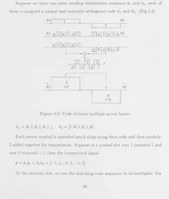
38
4.2.3 Multiuser detection with Viterbi algorithm and m-algorithms 41 4.3 Adaptive Structure
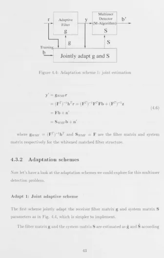
4.3.1 Receiver filter front-end 4.3.2 Adaptation schemes
4.3.3 Adaptive combinations 4.4 Simulation results
4.5 Conclusions
5 Robust Viterbi algorithms
5.1
5.2
The purpose .
The decoding problem
42 42 43 45
46
46
51 51 525.2.1 The system 52
5.2.2 Optimal decoder with perfect knowledge of channel noise 54 5.2.3 Optimal decoder with knowledge of channel noise a priori
probability. . . . . 54
5.3 Minimax robust decoder
5.3.1 Optimal minimax robust decoding algorithm
55
55 5.3.2 Minimax robust decoder based only on path likelihood ratio 61
5.3.3 Minimax robust decoder based only on branch likelihood ratio 63
5.4 Performance Analysis. 5.5 Simulations results
5.5.1 Example noise models
64
68
5.5.2 Different types of noise 5.5.3 Complicated mixed noise
5.6 Conclusions
6 Robust APP algorithms 6.1 The purpose
6.2 Robust Turbo decoder
6.2.1 Turbo code . 6.2.2 Robust MAP decoder. 6.3 Robust LDPC decoder
6.3.1 LDPC code and decoder 6.3.2 Minimax robust LDPC decoder 6.4 Simulations results for robust APP decoders
6.4.1 Gaussian noise with different noise variance
6.4.2 Different types of noise . 6.4.3 Complicated mixed noise.
6.5 Conclusions
7 Conclusions
7.1 The incentive revisited
7.2 Summary of our Achievements.
7.3 Outlook for future works
A The Calculation of optimal minimax decision region
List of Figures
1.1 Structural diagram of the thesis 8
2.1 Trellis structure for Viterbi Algorithm .. . . .. . . 13
3.1 System block diagram of IST channel 23
3.2 Adaptation structure for lSI channel 26
3.3 Cascading FIR filter . . . 27
3.4 Adaptive receiver for 3 tap lSI channel 32 3.5 Adaptive receiver for 5 tap lSI channel 33
4.1 Multiple access philosophy 35
4.2 Code division multiple access basics 38
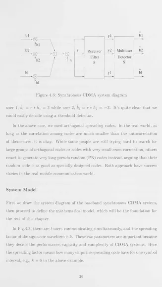
4.3 Synchronous CD:v1A system diagram 39
4.4 Adaptation scheme 1: joint estimation 43
4.5 Adaptation scheme 2: channel estimation. 45 4.6 Adaptive multiuser detection 5 user 10 spreading 48
4.7 Adaptive multiuser detection 5 user 31 spreading 49 4.8 Adaptive multiuser detection 20 user 31 spreading 50
5.2 A simple detection system
5.3 Optimal robust decoding example
5.4 A switching robust detector
5.5 A system with several error paths in the trellis
5.6 A single error event
58
59 60
62
65
5.7
5.8
Matched, mismatched and robust decoders in fixed channels . .. 67
Matched, mismatched and robust decoders in random mixed channel 68
5.9 Different type of noise with I = 0.5,1,2,4 70
5.10 Robust VA decoder in channels with uncertain types of noise (1) 72
5.11 Robust VA decoder in channels with uncertain types of noise (2) 73
5.12 Robust VA decoder under mixed type noise channel. . . . 74
6.1 The original Turbo code . . . 76
6.2 Gaussian noise with J2 = 2,1.5,1,0.5 . . . . . . . . 84
6.3 Robust Turbo decoder in uncertain variance noise channel 85
6.4 Robust Turbo decoder in different types of noise channel(l) . 86
6.5 Robust Turbo decoder in different types of noise channel (2) 87
6.6 Robust LDPC decoder in I
= 4 channel
886.7 Robust Turbo decoder under mixed type noise channell 89
6.8 Robust LDPC decoder under mixed type noise channel 1 90
6.9 Robust Turbo decoder under mixed type noise channel 2 91
6.10 Robust Turbo decoder under mixed type noise channel 3 92
II,
Chapter 1
Introd uction
Vigourous writing is concise. This requires not that the writer
make all his sentences short, or that he avoid all detail and treat his
subject only in outline, but that every word tell.
- WiLLiam Strunk Jr., I!The Elements of Style"
1.1
Background
1.1.1
The need for
speed
In recent years, there is increasing hunger for more speed out of the communi-cation systems, thanks to the bandwidth-thirsty applicommuni-cations such as streamed audio/video and graphic intensive world wide web traffic. It is predicted that in a global point of view, data related traffic will soon surpass voice related traffic in the telecommunication networks in the very near future. Actually in some countries, this pattern of traffic is already a matter of reality [35J [63J.
To meet the challenge of such dramatic change in the traffic volume and pattern, the old faithful voice-oriented telecommunication systems have to be
high-capacity (hundreds of gigabit to terabits per second) and exceptionally high
quality (high signal to noise ratio. low attenuation) fibre optical transmission,
thanks to the dense wavelength division multiplexing technology and light
am-plifier technology based on Erbium-doped fibre [64]. On the business side, due
to the extensive de-regulation waves sweeping through all the continents, there
have never been more companies in history than today that are beavering around
wiring up the globe with fibres [23] [62].
With pressure on the backbone relatively eased, the bottlenecks now appear to
fall in the user local loop. a telecommunication term which means the connection
between the subscriber and the end office of service provider [17] [18] [36]. In
today's communications landscape, the local loop will usually take the form of,
among many others, the twisted copper wire telephone line, the coaxial cable from
your pay TV company or the wireless radio link between a mobile phone and a
base-station. These local loops are heavily polluted with environmental and
man-made noise, crowded with lots of inter-user and inter-cell interference, shadowed
and faded. In a word, they are telecommunication engineer's nightmare.
1.1.2
Powerful algorithms
To squeeze more speed out of such "bad" channels while maintaining high quality
transmission, powerful algorithms are needed to replace traditional algorithms.
fn communication theory, it has long been known that a sequence based
maxi-mum likelihood detector (such as the Viterbi algorithm) or a posterior probability
detector (such as the one used in Turbo decoder) are optimal. But the
com-putational complexity of such algorithms are prohibitive when the receiver gets
more complicated. In the past, it is the feasibility that prevented the successful
deployment of these powerful algorithms in commercial communication system,
although they have been extensively used in military and deep space communic
In recent years, due to the significant breakthrough in the computing and
microchip technology, we have so much computing power at such a low cost, low
power consumption and small physical profile that we can implement some really
sophisticated algorithms in the communication device-not only at the base-station
or central switch level, but also at handset level. So there is refreshed enthusiasm
in both academia and industry to further explore the application of those optimal
algorithms.
There are also a wealth of reduced complexity algorithms based on the above
optimal algorithms, which show a very promising compromise between complexity
and performance. They generally have performance much better than traditional
algorithms, and in most cases close to the significantly more complicated optimal
one. They have increased computational demand than traditional algorithms, but
not to the degree typically associated with most optimal algorithms.
So to our special interests are the following powerful algori thms (wi th more
detai Is discussed in their correspond i ng chapters):
1. The Viterbi algorithm and reduced-complexity ~'I-algorithm in inter-symbol interference Channels; (Chapter 3)
2. The Viterbi algorithm and red uced-complexity M-algorithm in multiuser
de-tection for direct sequence Code Division Multiple Access systems; (Chapter
4)
3. Viterbi algOl'ithm for convolutional code decoding; (Chapter 5)
4. I\Iaximum a posteriori probability (~1AP) decoding algorithm for Turbo
code; (Chapter 6)
1.2
The Uncertain Elements and the Two White
Knights
to
the Rescue
Unfortunately, these powerful algorithms are prone to performance degradation when there are uncertainties in the communication system, which will seriously jeopardize their usability in practice. So we resort to the traditional wisdom of
living creatures coping with changes in the environment: either adjust accord-ingly to adapt to the environment, or have some kind of robust nature that can accommodate any perceivable outcoming.
1.2.1 Knight Adaptive
An example of the unpredictable nature of channel can be easily found in wireless
cell phone systems. Users of mobile phones are moving around, exiting one cell and entering another, their line of sight distance to the base station is changing all
the time. The faithful and diligent power control system will be busy increasing or reducing the emission power of handset and base station to maintain a radio link
of stable power level between them. This will generate a ever-changing inter-user interference effect on other users in the same or adjacent cells. When the mobile user roams the edge of a cell or the intersection of different cells, this kind of interference to other users can be so strong that it will cause annoying glitches and occasional drop-offs for mobile users.
Besides, there are also instabilities of equipment either in the network or at the user side, due to environmental heat and humidity, weather, component ag-ing, malfunction, failing and software runaway. They will also introduce some uncertain elements to the communication system.
In these cases, we would like to implement some kind of adaptive scheme in the communication system to track the current parameters of the system model
The adaptive receiver can combat lots of these uncertain elements.
1.2.2 Knight Robust
But sometimes even adaptation cannot solve the problem, therefore a robust re-ceiver structure is needed for the worst possible condition.
In wireless radio channels. the environmental noise in the channel can nor-mally be approximated as additive white Gaussian noise for practical purposes
of designing communications systems. But some natural phenomenon such as lightening can cause impulsive noise. There is also a lot of man-made noise in
the channel, such as automotive ignition noise, power-line noise and etc, which
changes from place to place and time to time [50], [37]. The characteristic of one
type of man-made noise is impulsive with a typical rate of 10-50 impulses/second,
[50]. For a mobile phone with a data rate of 10 kbits/s, it could experience up to one impulse every 200 bits (roughly every speech packet will be affected). For a high frequency radio INith a lower data rate of 1 kbits/s, the situation will be
worse. Some types of man-made noise can be approximated by Gaussian noise, while others might only be modelled as other types of noise (for example, Laplace noise) [30]. Furthermore, even in Gaussian channels the maximum a posterior'i
probability decoder needs to estimate the noise variance. The accurate estimation
of these noise parameters could range from being very difficult to impossible in practice.
1.3
Ov
e
rvi
e
w of th
e
th
e
sis
1.3
.
1
Contributions
The major contributions of our research work are:
• Propose the new adaptive structure combining the joint adaptive scheme
with the whitened matched filter and M-algorithm, which is both well
per-forming and simple to implement.
• Apply the adaptive structures not only to maximum likelihood sequence
detection in inter-symbol interference channel but also multiuser detection
in code division multiple access systems.
• Provide useful guidelines for communication engineers in designing adaptive
Viterbi algorithm or M-algorithm backed receivers; compared merits and
disadvantage of the various adaptation combinations.
• Study the optimal robust detecting problem in a generalized way so that it
can provide insight into extending the robust algorithms into various other
areas, which will open a rich vein of related research.
• Apply the minimax robust kernel to the maximum likelihood sequence
detec-tor Viterbi algorithm, which is widely used in convolutional code decoding.
• Apply the minimax robust kernel to various a posteriori probability (APP)
algorithms such as the decoders for Turbo code and low density parity check
code, aiming to improving the robustness of decoders for these codes in
uncertain channels or channels hard to be estimated accurately.
• Tackle the problem of mixed noise within one transmitted packet using our
robust algorithms with success, which is not yet reported in any other robust
• Analyze the error performance of our minimax robust decoder and find the robust decoder has superior performance over the mismatched decoder and
can perform very close to the optimal matched decoder. This conclusion is also supported by the numerical simulation results.
• Conclude from our analysis and experiment that our robust kernel is very easy to be implemented on top of the traditional decoder. And there are no
or little computational complexity increase due to the introduction of the robust kernel. These are excellent characteristics for practical deployment.
1.3.2
Publications
• "Breadth-First Algorithm with Adaptive Forney Structure for lSI
channels", Zheng Li and Lei Wei, Proceedings of Global Communication
Confe1'ence (GlobalCom'98). Sydney Australia, Nov. 8-12 1998.
• "On Robust Decoding Algorithms", Zheng Li, Lei Wei, Ylatthew James and Ian Petersen, Proceedings of International Conference in
Communica-tions (lCC'99), Vancouver Canada, June 7-10 1999.
• "A Minimax Robust Algorithm", Lei Wei, Zheng Li, Matthew James and Tan Petersen, accepted by IEEE Transaction on Information Theory.
1.3.3
Thesis architectur
e
Introduction
Chapter 1
Literature Review
Chapter 2
Adaptive Primer
Adaptive Receiver for
lSI Channel Chaoter 3
Adaptive Receiver for Multiuser Detection
Chapter 4
Robust Primer
Robust Viterbi Algorithm Chapter 5
Robust APP algorithms Chapter 6
[image:22.403.38.383.42.492.2]Conclusions Chapter 7
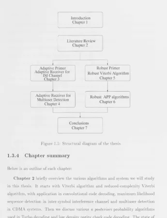
Figure 1.1: Structural diagram of the thesis
1.3.4
Chapter summary
Below is an ouUine of each chapter:
Chapter 2 briefly overview the various algorithms and system we will study
in this thesis. It starts with Viterbi algorithm and reduced-complexity Viterbi
algorithm, with application in convolutional code decoding. maximum likelihood
sequence detection in inter-symbol interference channel and multiuser detection
in CDMA systems. Then we discuss various a posteriori probability algorithms
used in Turbo decoding and low density parity check code decoding. The state of
art of both adaptive receiver design and robust decoding techniques are reviewed,
research work.
In Chapter 3 we will devise several adaptive structures for sequence detection in inter-symbol interference (lSI) channels based on minimum mean square error criterion. First, we will briefly discuss the Viterbi algorithm(VA) and various reduced complexity M-algorithm (MA), which keeps certain number of survival paths (m) on each stage in the decoding trellis. At the receiver filter front-end, we will present both matched filter (MF. or the Ungerboeck structure) and the whitened matched filter (W1I,IlF. or the Forney structure). In either of the two filter structures, we need to adapt the receiver filter taps and the system model parameters. We will propose two adaptive schemes, one jointly estimate the filter tap and system model, while the other estimates the channel model first and then calculates the filter tap and system model mathematically. Thus we have a full set of combinations of different filter front-ends, adaptive schemes and sequence detectors. To compare the performance of these combinations, we will carry out extensive simulations on various lSI channels using a Global System for Mobile Communications (GS1I,Il) type packet frame. The results will provide us with a guide on how to choose from these adapti ve structures for different purposes and some insight on why they will differ.
In Chapter 5 we will propose the minimax concept and devise our robust receIvers. The minimax idea, simply put, tries to optimize for the worst possible
scenarIo. In our case, it means how to minimize the maximum error probability associated with all possible noise types. We approach the problem from a generic viewpoint, aiming to find the optimal robust algorithm. Although it provides us with a theoretical framework for designing robust algorithms, it appears to be too
complicated even for a very simple problem. Our simplified near-optimal minimax robust algorithm is then proposed based on both the optimal robust algorithm
and intuitive observation. After refinement, this robust kernel is injected into the Viterbi algorithm convolutional code decoder. There is generally no or slight
computational overhead for adopting the robust scheme, and there are only a few structural adjustments needed in updating corresponding traditional receivers. All of the above attributes are very attractive for practical implementation of our
robust algorithms. Our robust decoders generally outperform the mismatched de-coders and is always very close to the optimal matched decoder. Our performance analysis also supports such observations.
Chapter 6 further extends the application of robust scheme into various a
posteriori probability (APP) algorithms. We start with the Bahl, Cocke, Jelinek and Raviv 's algorithms [8] for Turbo code decoding, followed by the Gallager and McI<ay's decoding algorithms (GLjMN, [29],[44]) for low density parity check code. Our robust algorithm can handle mixed noise within a transmitted packet as well as across multiple packets, which is a unique contribution compared to
other noise estimation methods appeared in the literature. Our simulation results
will again illustrate the performance advantage we can achieve by improving the
traditional APP algorithms with minimax concept. This performance edge,
to-gether with the implementation efficiency, will surely make our robust scheme an interesting new technique in improving lots of the powerful decoding algorithms
widely used in today's error control coding systems.
Chapter 2
Literature Review
" .. . See human beings as though they were in an underground cave-like dwelling with its entrance, a long one, open to the light across the
whole width of the cave. They are in it from childhood with their legs
and necks in bonds so that they are fixed, seeing only in front of
them, unable because of the bond to turn their heads all the way
around. Their light is from a fire burning far above and behind them.
Between the fire and the prisoners there is a road above, along which
we see a wall. built like the partitions puppet-handlers set in front of
the human beings and over which they show the puppets".
"Then most certainly," I said, "such men would hold that the truth is
nothing other than the shadows of artificial things.))
- The Cave ji'om Book VII of Plato's Republic
2.1
Viterbi algorithm
,
M-algorithm and
Appli-cations
2.1.1
Vit
e
rbi
algorithm
The Viterbi algorithm was originally proposed by Andrew J. Viterbi for decoding convolutional codes [79] [80] [81]. It is a recursive optimal solution to the problem of estimating the state sequence of a discrete-time finite-state Yfarkov process
observed in memory less noise. It can achieve asymptotically optimal performance
in additive white Gaussian noise channel. The idea is also known as "dynamic programming" in operations research.
We can map the discrete-time finite-state Markov process into a trellis, with each node standing for a distinctive state at a given time, each vertice or branch representing the legitimate transition from one state to another in the time
se-quence.
State
00
10
01
11
k=O k=l k=2 k=3 k=K-2 k=K-l k=K
o
o
Figure 2.1: Trellis structure for Viterbi AlgorithmSuppose x = [XI, X2, . .. , xj(] (J( is the length of x) is the vector of states in
the path whose path metric -In P(x, r) is minimum. P(x, r)
=
P(x)P(rlx)f{-l 1\--1
=
II
P(Xk+IIXk)II
P(Tkl xk+l, Xk).k=O k=O
J\'-l
- In P(x, r)
=
2)
-In P(Xk+llxk) - In Phlxk+l, Xk)) k=Ol\ -I
=
L bmkk=O
in which bmk stands for the branch metric at time slot k.
(2.1)
(2.2)
And this standard shortest-path problem can be solved by the following steps:
Initialization. Start with Xo state, set the state metric sm(xo) to zero and all
other state metric to infinity.
Forward recursion: Compute the state metric sm(xk+d = sm(xk)
+
bmk for allpossible transitions from state Xk to state Xk+l; find the mini
-mum of smk+l for each Xk+l; store sm(Xk+l) and corresponding
survivor i(Xk+l)' Set k to k+ 1 and repeat the forward pl"Ocess
until we hit XK.
Backward tracing: For finite length sequence the algorithm stops at time j{ with the shortest complete path, we can then retrieve this path from the stored survivor i(x,,-)
2.1.2
Reduced-complexity VA
Viterbi algorithm is attractive for its asymptotical optimal performance. One
of its major drawback, however, is the large memory and computation, which is
It's the complexity issue of Viterbi algorithm that prevents it from ubiquitous deployment in practical communication system.
In light of this, several reduced-complexity near-optimal Viterbi algorithms are proposed, such as M-algorithm and T-algorithm [4] [87] [7] [5]. The major focus is on how to reduce the number of survival paths kept throughout the forward recurSions.
For the :vi-algorithm. the best m extended paths are kept as survivors. tor T-algorithms, only those paths whose path metric is within a threshold of T from the best path is stored. A combined M- and T- algorithm, or hybrid MT-algorithm, is a T-algorithm whose number of survivor paths are further restricted to m. If the m
= 2,,·-1
or T=
inf, then both algorithm will become the optimal Viterbi algorithm. On the other extreme, if m=
1 or T=
0, then these algorithms is no difference from decision feedback detector. From the above discussion, we can conclude that these reduced-complexity Viterbi algorithms are fine tunable to accommodate different tradeoffs in complexity and performance.And there are strong analysis and simulation results suggesting that these significantly simplified algorithms can achieve near optimal performance [83] [84]. Instead of reducing the surviving paths in the full-sized trellis, other reduced complexity techniques try to reduce the number of states of the trellis, such as reduced state sequence detection [16] [20] [19], and using a linear or decision feedback equalizer to shorten the lSI duration [9] [21] [38] [54] [85] [31].
2.1.
3
Application of VA and
MA
For convolutional code and lSI channel, signals are correlated in the time
space, or the transmitted signal Sk is a linear combination of information signals
[6 k, 6k- 1, 6k- 2, ... ,6k- L]
(L
is the memory length). For convolutional code, the con'elation will be either 0 or]; for lSI channel, the correlation factor will be the channel taps. The information sequence [6k , 6k -1, bk - 2 , . .• , bk - L ] corresponds tothe state or node in the trellis graph, and the branch metric could be computed
in proportion to -In P(TkI6k) where Tk = Sk
+
11k.For synchronous CD.YfA systems. the correlation exist among different
simul-taneously transmitting users in the code space. Another level of time space
cor-relation is added for asynchronous CDMA systems.
2.2
A
posteriori
probability
algorithms
R.ecently. the two-lVay a posteTioTi probability (APP) decoder has attracted lots
of attention. due to its application in Turbo decoding
[8] [10]
and Low-DensityParity Check (LDPC) decoding
[28] [29] [42]
.
Both the Viterbi algorithm andtwo-way APP algorithms are special cases of min-sum and sum-product algorithms
[86].
Some significant developments in understanding these two-way decodingalgorithm have been reported in
[69],
[43],[26],
[6].
In[25]
Forney provided adetailed discussion of the two-way algorithms as well as an overview of their rich
history.
The TvVL (Tanner. Wiberg, Loeliger) graph provides us with a convenient way
of visualizing various coding schemes and insights into the comparative merits
and shortcomings of those code structure and their decoding algorithms. In TWL
graphs, nodes represent symbols, state and checks. The relation between nodes are
legal state transition or parity check constraints. The two-way min-sum and
The practical decoding algorithms for most powerful codes, such as Turbo code, LDPC code and tail-biting code can be derived from min-sum and sum -product algorithms taking into account that these codes are inherently represented by graph with cycles. They work very well as long as the cycles are long enough
that cyclical dependencies die out as they propagate around a cycle.
[25
]
Besides these optimal two-way algorithms, there are several suboptimal
for-ward only algorithms developed for reducing the complexity [3] [2J [89].
2
.
3
Adaptive detection
2.3.1
Ad
a
ptiv
e
equalization for
lSI
There are lots of research work on adaptive equalizer design for lSI channel
[
27]
[
53
] [
55
],
and we could categorize them into adaptive linear equalizer, adaptivedecision-feedback equalizer and adaptive channel estimator for maximum likel
i-hood sequence detection (Viterbi algorithm). We will skip over the first two and
focus our attention on the last category due to its comparatively good
per[or-mance.
Ungerboeck
[7
0]
proposed an adaptive matched filter front-end coupled withViterbi algorithm sequence detector structure, which could simultaneously adjust
the demodulating carrier phase and sample timing, approximate the matched filter
by a transversal filter. and estimate lSI present at the output of the approximated
matched filter. Stochastic steepest-descent algorithms is used to derive the
recur-sive adaptation steps. It differs from Forney's whitened matched filter structlll'e
[24J with its matched filter front-end and adaptive structlll'e.
As we discussed in the previous section, maximum likelihood sequence D
e-tector(MLSD) implemented by Viterbi algorithm has exponential complexity in
equal-izer to constrain the length of the equivalent channel impulse response. In
[31],
Gu proposed an embedded decision feedback equalizer(DFE) to act simultane-ously as a pre-whitening matched filter. a compensator for channel distortion and
an adaptive equivalent channel impulse response estimator while the embedded MLSD detector operates on the signals predicted by the embedded DFE. This
could adaptively trace the simplified channel model.
2.3.2
Adaptive multiuser det
ec
tion for CDMA
The multiuser detector for CDMA systems depends on various system parameters such as received signal amplitude and cross-correlations which are fluctuating both in time and space. Therefore, the selr-tuning adaptive multiuser detection attracted much interest in recent years.
Verdu has a good overview on adaptive multiuser detection in [77]. In brief, there are decorrelating detector [39]
[40],
linear multiuser M\1SE detector[88] [41]
[56],
tentative-decision based detector [72] [73][
15],
blind multiuser detector and Neural network based detector.2.4
Robust decoding
2.4.1
Non-Gaussian nOIse
Although the assumption of white Gaussian noise is quite appropriate for many applications, it is well known that in many practical channels the noise distribution can be hardly modelled as Gaussian due to the existence of various impulsive noise [82J [IJ [37J. This is particularly true in urban and indoor radio channels for mobile and portable communications. For detailed report on the measurement and modelling methods please refer to [12J [13J [45J [46] [51 J and the references therein.
Non~Gaussian impulsive noise can be quite detrimental to the performance of
traditional detector based on Gaussian assumption. On the other hand, a properly modelled and estimated noise model can be quite beneficial to the detector design. There have been numerous efforts over the past three decades in the area of signal detection in impulsive noise [34J [47J [48J [65J [66J [67] [74J.
2.4.2
Robust decoding based on noise
estimation
Several recent works use robust estimation method to address the problem of Turbo decoding in channels with unknown noise PDF. Summers and Wilson in [68J and Reed and Asenstorfer in [58J focus on how to efficiently and accurately estimate the noise variance of each block for Turbo decoders. Huang and Phamdo in [32] deals with how to accurately estimate the noise distribution within a family of noise models. This is still a relatively new research area which is generating more and more interest from both academia and industry.
over-estimating noise variance is less detrimental than under-estimating variance, tolerating a mismatch of several decibels without significant degradation. The reason behind this phenomenon is not presented, though.
Summers devised a blind algorithm to estimate tIle unknown SNR from each code block prior to decoding that block, which do not require the transmission of training symbols. He used a heuristic approach which is based on sums of the squared receiver values and sums of their absolute value. This online estim a-tion method do not degrade performance appreciably relative to the known SNR condi tions.
Reed proposed a Novel Variance Estimation Technique (NOVEL) based on the assumption that the output of Turbo decoder is approximately equal to the data sent. This variance estimation method is however one block behind that of the conventional techniques because the decoder result is required before the estimation can be made. The performance analysis and simulation results show NOVEL is better than conventional algorithms at low S:\fR region, where the Turbo code is normally used.
Chapter 3
Adaptive receiver for
lSI
channel
3.1
The purpose
Nothing is permanent but change. - Heraclitus
The inter-symbol interference (lSI) can seriously affect the performance of re-ceiver in wireless and wireline communication systems so it's important to devise
adaptive schemes to combat this problem.
There are lots of research work on adaptive receiver design for lSI channel.
However little previous work are focused on the reduced-complexity Viterbi al go-rithms or more specifically the M-algorithm. And we know that M-algorithm can achieve near optimal performance at significantly low complexity [83J [84J.
In this chapter, we will start with a primer on lSI channel, followed by details
of matched and mismatched filter front-ends, ViLerbi algorithm and M-algorithm detector back-ends, jointly adaptation scheme 1 and channel estimation scheme
2, then arrive at a full combination of adaptive structures. The simulation results
will give us insight into how to choose among these combinations when designing
3.2
Sequence detection in lSI channel
3.2.1
What is inter-symbol interference (lSI)
channel?
So what is inter-symbol interference channel, also know as lSI channel? Let's first consider a simple analogy:
Suppose you are in the mountains, you start to recite Homer's Iliad to show
your friends your talents as an orator. Your voice is loud and clear and you
are about to make an impression, however, something happens. The reverberant sound of yourself several seconds ago bounce back from the mountains and add right on top of your current recital, making your friends hard to distinguish any
word, let alone admire your talent. So what's the problem? Sound travels in different paths which result in different delays in reaching the listener, and they get mixed up with the original sound.
Inter-symbol interference channel has the similar mechanism. Due to the dif-ferent paths source signal traverse, various signals arrive at the receiver with dif-ferent time delay (or phase shift) and amplitude attenuation. This phenomenon frustrates telecommunication engineer because the original signal is not only
con-taminated by the environmental noise. but also by several distorted copies of itself, which further complicates the detection task.
3.2.2
System model
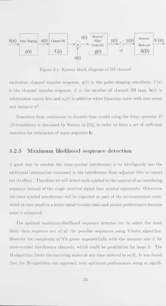
Before we move onto the solution to the inter-symbol interference problem, let's first formulate it. The system block diagram of the transmitter and receiver over
typical IS] channel is shown in Fig.3.1.
The signal at the output of the channel is
r(t) =
h
(t) * b
(t)+
no(t),where
*
denotes convolution. r(t) is the received signal, h(t)(3.1)
b( n)
.1
Pulse ShapingX(t)
Channel lSI1
':,:;"
I
y(t)j;; y(o)
I
",w",I
b'(o)
+
Front-end ; Back-cndpet)
CCt)
get)
nTSeD)
net)
Figure 3.1: System block diagram of lSI channel
equivalent channel impulse response,
p(t)
is the pulse shaping waveform,C(t)
is the channel impulse response, L is the number of channel lSI taps, b(t)
is information source bits andno(t)
is additive white Gaussian noise with zero mean and variance (J2Transition from continuous to discrete time model using the delay operator D (D-transform) is discussed by Forney in [24], in order to form a set of sufficient statistics for estimation of input sequence b.
3.2.3
Maximum likelihood sequence detection
A good way to combat the inter-symbol interference is to intelligently use the additional information contained in the interference from adjacent bits to cancel
out its effect. Therefore we will detect each symbol in the context of an interfering sequence instead of the single received signal that symbol represents. Otherwise the inter-symbol interference will be regarded as part of the environmental noise, which in turn result in a lower signal to noise ratio and poorer performance because noise is enhanced.
The optimal maximum-likelihood sequence detector try to select the most likely data sequence out of all the possible sequences using Viterbi algorithm.
However the complexity of VA grows exponentially with the memory size L for
[image:37.402.33.363.0.607.2]signifi-cantly less than 2L [84]. The tradeoff between performance and computational complexity is very attractive for real world application.
3.2.4 Filter front-end: MF and WMF
There are two basic types of receiver filter for lSI channel: one is the U nger-boeck's matched filter structure; another one is the Forney's whitened matched filter structure.
Matched filter (Ungerboeck structure)
The matched filter (in this chapter we restrict to real signals) can be expressed as
gMF(D) = h(D-1 ).
The signal after the matched filter will be
y(D)
=
h(D-l)h(D)b(D)+
h(D-1)n(D)=
R(D)b(D)+
z(D),(3.2)
(3.3)
where n(D) is white Gaussian noise, R(D) = h(D-l)h(D) is the system cor-relation matrix and z(D) is a coloured Gaussian noise sequence, whose correlation matrix is R(D).
Using the maximum likelihood criteria, as shown in [70], we can get the metrics for the Viterbi algorithm
In(6S,6~, ... ,b~_l,b~)
=
In-l(bS,b~, .. ,b~_I)L
+
b~(2Y
n
-Sob~
-2LSlb~_
I
)'
(3.4)1=1
Here In is the state metrics ending symbol bit b~; the second part of the right
filter structure. Because of the symmetrical characteristics of the matched filter
structme, 5_1 = 51, only one side is needed to calculate the metric.
Whitened matched filter (Forney structure)
In [24], it was shown that after the whitening Alter gwP
=
(F(D-1)J-l, where R(D) = F(D)F(D- 1). We havey'(D) = gwp(D)y(D)
= F(D)b(D)
+
n'(D)(3.5)
= gWMP(D)b(D)
+
n'(D),gWMP(D) = gWPg.MF
(3
.
6)
=
F(D-1t1h(D- 1),where n'(D) is whitened Gaussian noise sequence.
According to [24], the metric for the maximum likelihood criteria could be computed as following
L
In(bS,b;, .. ,b~_l,b~) = J(bS,b'1 , •• ,b~_I)
+
(Yn - LF,b~_,?,I~O
(3.7)
where FI is the system impulse response of the whitened matched filter structure.
3.3
Adaptive Structure
3.3.1
Adaptation Schemes
Here we will consider two groups of adaptation schemes:
Sequence
r( n)
1
Adaptive FIRI
Y
~
n!
I
DetectorI
b'
(n
1
Filter (M-Algorithm)
g(~)
II
IS~D)
g
:
S
Adaptation Scheme
b(n)
1
L-
_ _ _ _ _ _
_
[image:40.403.31.374.32.582.2]Training
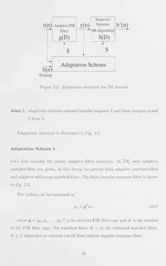
Figure 3.2: Adaptation structure for lSI channel
Adapt 2: adaptively estimate channel impulse response h and then compute g and S from h.
Adaptation structure is illustrated in Pig. 3.2.
Adaptation Scheme 1
Let's first consider the jointly adaptive filter structure. In [70], only adaptive matched filter was given. In this thesis, we present both adaptive matched filter and adaptive whitening matched filter. The finite impulse response filter is shown in Pig. 33
The system can be expressed as
T
Yn
=
g rn,(3.8)
where g = [go, gl,· .. , gKjT is the receiver FIR filter taps and J{ is the number of the FIR filter taps. For matched filter, J( = L; for whitened matched filter,
---EJ
1
---=
~
y(D)
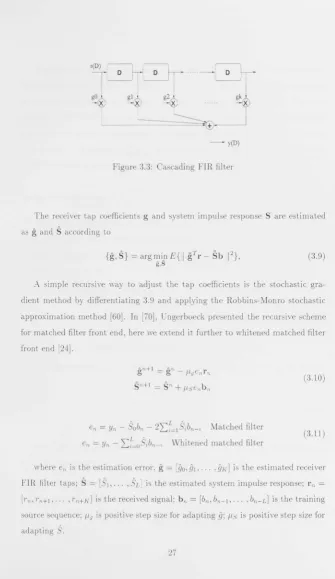
Figure 3.3: Cascading FIR filter
The receiver tap coefficients g and system impulse response S are estimated
as
g
andS
according to{g,S}
= argmi}1E{11 gTr -Sb
In
,
g,S (3.9)
A simple recursive way to adjust the tap coefficients is the stochastic
gra-dient method by differentiating 3.9 and applying the Robbins-:'v'Ionro stochastic
approximation method [60]. In [70], Ungerboeck presented the recursive scheme for matched filter front end, here we extend it further to whitened matched filter
front end [24].
gn+l = gn - I-'genrn
sn+1
=
sn+
I-'senbnA L A
en = Yn - Sobn - 2Li=1 Sibn-i Matched filter
en = Yn - L~oSibn-i Whitened matched filter
(3.10)
(
3.11)
where en is the estimation error,
g
=[90,91,'
.. ,9[,']
is the estimated receiverFIR filter taps;
S
=
[05
1 , . ..,Sd
is the estimated system impulse response; rn =[Tn' Tn+ I, . ,Tn+h'] is the received signal; bn = [bn, bn-l, ... ,bn- L] is the trai n ing
source sequence; I-'g is positive step size for ada.pting
9;
1-'5 is positive step size for [image:41.403.31.366.3.582.2]The gradient based recursive adaptation method are very simple to implement. When the step size is chosen small enough, it will converge to the global optimum no matter what initial point it started [70J. In the GSM system [57], there are only 26 bits of training signal per packet, which is not easy for gradient based algorithms to achieve satisfactory convergence. In practice, we find by choosing step size fls ::::;
i
and flg ::::; Tofls, combining with re-using the training bits, thisjoint adaptation scheme can yield good results in typical noise environment.
Adaptation Scheme 2
An alternative adaptive scheme will be estimating the equivalent channel model h in (3.1) first and then calculate Sand g fmm h, wh.ieh we denoted as adaptation scheme 2. Similar schemes has been used to compute other equalizer (LE/DFE) coefficients such as [22J.
The channel impulse response h can be estimated as
h
according to1;
= argm)nE{11 T - l;bIn
(3.12) hwhere
[h
i
,'
..
,
hd
is the estimated channel impulse response.The recursive adaptation of
h
can be obtained using stochastic gradient algo-rithml;n+1 = l;n
+
flhenbn,L A
en = Tn - ~i=ohibn-i
(3.13)
where en is the estimation error, I;
=
rhO,
hI,
...
,
hLJ
is the estimated channelimpulse response and flh is positive step size for adapting
h.
After we get the estimate of channel coefficients
h
,
the system correlation matrix could be calculated by:If we want to use the matched filter structure, we could simply use
gM
F' =h
and SMF' =It as F
IR filter and system impulse response; if we want to use the whitened matched filter structure, then we could use the window Cholesky decomposition (R(D) = F(D)F(D-l)) to get the whitened matched filter system matrix SWMF' =F
, wh
ich in turn could be used to get the receiver FIR filtergIVAlF'
=
F
-'
l
;
.
(3.15)This way, the noise whitening requirement can be guaranteed by the Cholesky factorization process. But this could also be costly due to the additional matrix computation.
3.3.2
FIR filter front-end
and adaptation
scheme
combi-nations
According to the above discussion on "receiver FIR filter structure"and "Adap-tation schemes'" it is quite clear that we have a few interesting combinations to study, which is shown in the following graph:
(
wM~,
)
(:~:;:l
) (
M:~m
)
)
Adapt2
The abbreviations used in the graph are listed as follows:
M F Matched filter;
WM F: Wh i tened matched filter:
VA: Viterbi algorithm;
The adaptive whitened matched filter schemes coupled with M-algorithm is of great interest to us because they are the hope for achieving near optimal perfor-mance at a very low receiver complexity.
3.4
Simulations results
In this section, we study the different adaptive receiver structures under a GSM style environment. The data packet structure is similar to that in the GSM system (140 bits per packet, of which 26 are training bits); pulse shaping is rectangular pulse. The channel has 3 taps [0.407,0.815,0.407] [52], memory length L = 2, i.e. the total number of states is 4. In the graphs, F denotes channel parameters known and fixed; Al and A2 denotes adaptive scheme 1 and 2 respectively. The simulation results are in Figs 3.4(a) and 3.4(b).
We also did simulation on a 5 tap lSI channel
[0.2917,0.4941,0.5842,0.4941,0.2917]' L = 4, in Figs 3.5(a) and 3.5(b).
3.5
Conclusions
From the graphs we can find that if the channel parameters are known and fixed, with Viterbi algorithm, both the MF and WMF can get identical bit error perfor-mance. But when we use M-algorithm with a small m, the performance of matched filter structure degrade sharply compared with that of Whitened matched filter. For the latter, there is very minor performance degradation. So for low-complexity detector like M-algorithm, it shows that whitened matched filter generally per-forms better.
However the computational complexity of A2 (there are overhead for Cholesky decomposition and matrix multiplication) is much greater than that of Al. This overhead is averaged among the information carrying bits (or pay load) in a packet,
so it would be quite significant for small packets or moderate for longer packets. Another point worth noting is that the whitened matched filter using joint adaptation scheme A1 is somewhat disappointing, mainly because we truncated the infinite impulse response filter to simulate the whitened matched filter. When the parameters are known and fixed, such truncation will have minimum impact on the system performance. However. in an adaptive setup, sensitivity related issue comes into play which has a negative impact on the orthogonality constraint. Improvement on this specific combination will be part of the future work.
10.1 10.2 10. 3 a. w CO 10·' 10· s 10·e 7 10.1 10. 3
a. w
CO 10·· 10-5 10.6 7 - -<>---0...
- - MF(~ ,VA
I)+VA A2)+VA 'MA(2) 1),MA(2) A2),MA(2) --<>--MFI -0-MFI - MFI -+- MFI ___ MFI
7.5
-
""-'0... 8.5 ""-'0...9.5 10
Eb/No (dB)
(a) Matched filter front-end
- -WMF
-<>-WMF
-0-WMF
- WMF
-+-WMF ___ WMF
7.5 -0.;: (F),VA (A1),VA (A2),VA (F),MA(2)
(A1),MA(2)
(A2),MA(2)
8.5 9.5 10
Eb/No (dB)
10.5
10.5
(b) Whitened matched filter front-end
-
"",
'0_
11 11.5 12
-G.
11 11.5 12
[image:46.403.39.374.31.561.2]10'
10.1
10-2
il;
'"
10-310··
10.5
0
10'
10-1
10.2 a.
'"
'"
10.3
10.4
10.5 0
~ £l '= ; G: :' ~ ~ -()--~, '0-, -0-- _ ~
-"",s,~
" 0-' ,-',-'0.. ,
"" "0,
~
- MF(F)+VA-<>-MF(A1)+VA
--0-MF(A2)+VA
- MF(F)+MA(4) -+-MF(A1)+MA(4)
... MF(A2)+MA(4)
10 Eb/No (dB)
(a) Matched filter front-end
~
-WMF(F)+VA --0-WMF(Al)+VA -0-WMF(A2)+VA - WMF(F)+MA(4) -+-WMF(A1)+MA(4) -*-WMF(A2)+MA(4) 10E,jN, (dB)
,
,
(b) Whitened matched filter front-end , ,
,
<>
-0--0,
,
, ,
, C(
,
,
,
15
15
[image:47.403.35.383.36.514.2]~'
1:
Chapter 4
Adaptive multiuser detection for
CDMA system
The noise is so great, one cannot hear God thunder.
-R. C. Trench
4.1
The purpose
In this chapter, we will study adaptive multiuser receiver for direct sequence code division multiple access (DS-CD.YIA) system, which is of pivotal importance to our future mobile phone system. Growing from a technical novelty pioneered by Qualcomm's Interim Standard IS-95 based system (CDMAOne), CDMA is well heading for its prime time as the core standard for third-generation (3G) mobile telecommunication systems such as European/Japan's wideband CDMA (W-CDMA) and Qualcomm led CDMA-2000 system. The International Telecom-munication Union (ITU) is currently working on International Mobile Telephone system for 2000 (IMT -2000) to accommodate various proposals in hope of reaching a universal global standard.
be-tween performance and complexity and can adaptively adjust itself to reflect the variations in the communication system. The compromise is achieved by intro
-ducing a reduced complexity Viterbi algoriLhm- the m-algorithm, coupled with adaptive filter front-end. Various adaptation techniques are studied to estimate the channel and system parameters using a pilot training signal. Their compara-tive merits are evaluated side by side through numerical simulation.
4.2
Code Division Multiple Access system
4.2.1
Multiple access overVIew
Basically, there are three different kinds of multiple access or channelization t ech-nologies: frequency division multiple access (FDMA), time division multiple ac-cess (TDMA) and code division multiple access (CD:vrA). They separate different users of the trunk communication media from crosstalk by a different frequency band. time slot or spreading code Fig.4.1. Following is a brief overview of all these technologies within the context of mobile communication systems.
Code
Frequency
[image:49.403.38.363.30.586.2]Time
"Hard" Channelization: FDMA and TDMA
Both FDMA and TDMA are essentially <'hard" resource sharing approaches. They
have deep mentality roots in the permanent circuit oriented telecommunication
systems, which dated as far back as Edison's telephone system. They allocate a slice of channel resource to each active user, who have the absolute and sole use
of that resource during its session. lVith a predictable quality assurance.
Due to the precious nature of our frequency bandwidth, virtually all practical
communication system use certain version of FDMA technology. Giving an
ex-ample in the mobile phone arena: the first generation analog Advanced Mobile
Phone System (AMPS), assigns a bandwidth of 30KHz for each mobile user. The Global System for Mobile Communication (GSM) slices the radio channel into 200KHz slots which is further shared by another layer of multiplexing: TDMA.
[57J
The time division multiple access use the time domain diversity to segregate
different users. The above mentioned GSM 200KHz frequency band actually is
shared by 8 users, each occupying one of the eight time slots in a 4.615ms frame.
(The digital switched telephone system is another example, in which the time
slots not only channelize the trunk, but also facilitate the digital switching by
re-arranging the sequence of user slots entering and leaving a switching fabric.
[33])
"Soft" Channelization: CDMA
The CD:vrA scheme, a more flexible or "soft" channelization method, attracts
increasing popularity by overcoming some of the pitfalls of traditional "hard"
resource sharing methods. Here is an un-exhaustive list of CDMA's attractiveness
1. It scales better: We can add on more new users to a fully-utilized CDMA system without significantly compromising service quality for existing users. This is a so-called "graceful performance degradation" or "Something for
everybody" scenario. vVhile in traditional "hard" multiple access systems, when all the channels are allocated, no further user can communicate, or an "Everything or nothing" scenario.
2. It is more efficient: CD'VIA system have native support for variable data
rate and multiple Quality of Service (QoS). In a human to human conver-sation, more than 65 percent talk time is idle [37], so "hard" channelization will waste a lot of communication resources during non-talking period. For bUI'sty packet data transmission, we need not only variable data rate but
also dilTerent priority for different services.
3. It can provide better quality: Due to its spread spectrum technology, CDMA systems are inherently less prone to narrow-band interference and frequency-selective fading, which results in clearer voice and less drop-offs. In addition. soft hand-off between base-stations means you have less glitch or dropout for high mobility users when crossing cell boarders.
4. It is easier to deploy: No longer will we need complicated frequency
planning. Now we can easily re-use frequency within a cell or among adjacent
cells and implement hierarchical cell structure (microcells or picocells) to support "hot spot" (a place over-crowded by mobile terminals. e.g .. airport and sports stadium) and semi-fixed broadband data transmission.
These merits are to die for considering the hard challenges facing tel ecom-munication engineers in the wireless battlefield. That can partly explain why all the major vendors and standard bodies for wireless mobile phone systems, quarrelsome as they always are, more or less unanimollsly agree on using CDMA