RIT Scholar Works
Theses
Thesis/Dissertation Collections
5-16-1998
Aquanic: personal diving assistant tool
Watcharapong Treerattanaphan
Follow this and additional works at:
http://scholarworks.rit.edu/theses
This Thesis is brought to you for free and open access by the Thesis/Dissertation Collections at RIT Scholar Works. It has been accepted for inclusion
in Theses by an authorized administrator of RIT Scholar Works. For more information, please contact
.
Recommended Citation
A
Thesis Submitted
to the
Faculty
ofThe College
ofImaging
Arts
andSciences
In
Candidacy
for the
Degree
ofMASTER OF
FINE
ARTS
AQUANIC
PERSONAL DIVING
ASSISTANT TOOL
by
WATCHARAPONG
TREERATTANAPHAN
Chief Advisor: Craig McArt
Associate Advisor: Doug Cleminshaw
Date
~
@..f
E3
Associate Advisor: Kim Sherman
Date _ _
1
_,8_·Cf_6
_
Chairperson: Nancy Ciolek
Date _ _
--'-9_,
--=-g_,
-'-9--=-i
_
I, Watcharapong Treerattanaphan, hereby grant permission to the Wallace Memorial Library
of RIT to reproduce my thesis in whole or in part. Any reproduction will not be for comercial
use or profit,
Signature
_
Chapter
LIST
OF ILLUSTRATIONS
ii
1.
THESIS PROJECT DEFINITION
1
The Problem
The
Challenge
Process
ofDesign
2.
RESEARCH
AND
ANALYSIS
5
Visibility
Problem
Technology
3.
IDEATION
9
4.
PRESENTATION
11
5.
CONCLUSION
12
Technology
Design
Presentation
ILLUSTRATIONS
13
APPENDIX
54
Figure
Page
1.
Audio
Technology
14
2.
VRD
Technology
15
3.
Video
Technology
16
4. Location
ofeach component ofthe
Aquanic
17
5.
Design
conceptA1
andA2
18
6. Design
conceptA3
andA4
19
7. Design
conceptA5
andA6
20
8. Design
conceptA7
andA8
21
9.
Design
conceptA9
andA10
22
10. Design
conceptB1
andB2
23
11.
Design
conceptB3
andB4
24
12.
Design
conceptB5
andB6
25
13. Design
conceptB7
andB8
26
14.
Design
conceptB9
andB10
27
15. Design
conceptC1
andC2
28
16.
Design
conceptC3
andC4
29
17.
Design
conceptC5
andC6
30
18.
Design
conceptC7
andC8
31
19.
Design
conceptC9
andC10
32
20. Design
conceptD1
andD2
33
21.
Design
conceptD3
andD4
34
22.
Design
conceptD5
andD6
35
23. Design
conceptD7
36
24.
Design
conceptD8
andD9
37
25. Design
conceptD1 0
andE1
38
26.
Design
conceptE2
andE3
39
27.
Design
conceptE4
40
28. Design
conceptE5,
E6
andE7
41
29. Design
conceptE8,
E9
andE10
42
31.
Design
conceptF4,
F5
andF6
44
32.
Design
conceptF7,
F8
andF9
45
33.
Design
conceptF10,
G1
andG2
46
34.
Design
conceptG3,
G4
andG5
47
35. Design
conceptG6,
G7
andG8
48
36.
Design
conceptG9,
G10and
H1
49
37.
Design
conceptH2,
H3
andH4
50
38.
Design
conceptH5
51
39.
Design
conceptH6
52
THESIS PROJECT DEFINITION
The
purpose ofthis thesis
is
to
propose an underwaterdevice
to
be
carried or wornby
divers.
This device
would alleviatemany
problemsthat
divers may
encounter,
supporting
the
divers
as acommunication, navigation,
andbody
and environmentmonitoring
unit.The
Problem
Difficulties
of communication underthe
waterbetween
divers
The
ears candistinguish the direction
ofthe
soundaccording
to the time
delay
ofsound
in
the
air.Sound
can travelthrough the
water muchfaster
thanthrough the
air.Our
ears receive soundfrom
alldirections
atthe
sametime
in the water,
soourbrain
can notinterpret the direction
ofthe
sound source.Even
thoughsignlanguage
has been
usedefficiently
for
underwatercommunication,
one
diver
using
signlanguage first
needsto
getthe
attentionofthe
other.Due
to the
difficulties
ofdetecting
the direction
ofthe
sound underwater,
using
an acousticdevice
to
getattention underwaterwould not
be
useful whenthe
divers
are atany
distance.
Also,
somedivers have
aproblem with signlanguage.
This
is
especially
truefor
novicedivers
whohave
limited
experience withdiving
and communication under water.Difficulties
ofcommunicationbetween divers
andcrewmembersSome
charterboats
areequipped with adevice
thatemits asiren soundinto
the
waterin
orderto
recall submergeddivers
back to the surface, but the
divers
are not ableto
sendmessages
to the
crewmembers.There
is,
however,
away for divers
atthe
surfaceto
communicatewith crewmembers.The divers
have to stay
atthe
surfaceand use signIn
very
low
visibility
conditions,
losing
touch
withdiving
partneris
a major concern.Buddy
lines utilizing three-strand
twisted
line
with ahand
loop
at each end are usedin
orderto
avoiddiver
separation,
but
this
may
cause entanglement.Additionally,
the
divers may dive
in the
wrong direction
andhave
problemsmaintaining
the depth
because
of alack
of references.Using
signlanguage
and an underwaterslate,
whichis
a writable sheet ofplastic,
may
notbe
effectivein low
visibility
conditions, turbid water,
ordarkness.
Navigation
underthe
waterThe accuracy
ofthe
entry
and exit point canbe
affectedby
the
current.The strong
water movement
may
causethe
divers
to drift
away
from the
intended destination.
Safety
ofdiving
The
divers
are concernedaboutdecompression
sickness causedby
excessnitrogen
in the
blood
vessels.Time
anddepth
ofdiving
arethe
primary factors
that
may
cause an excess amount of nitrogenin the
blood
vessels.Preventing
injuries
whilediving
involves avoiding
accidents atthe
surface and underthe
surface.At the surface,
adive
flag
mustbe
placed atthe
diving
sitein
orderto
provide asignal
for
boaters,
but
sometimesthe
boaters
may
not perceive or recognizethe
purposeofthe flag. Under the surface,
injuries
from
animals occurbecause
ofthe
carelessness ofdivers
themselves.
Complexity
ofmanualdive
tableandplanning
A dive
table
canbe
complicatedto
read andinterpret,
but it
providesaccuracy
ofdive
planning.
A dive wheel,
another version of adive
planning
table, is easy
to read, but the
Locating
the
position ofthe
divers
Buddy
loss may
occurin
any
situation.There is
noway
to
precisely determine
the
diver's location
underthe
water.The ability
to
determine
the
position ofthe diver
underthe
water would
be
usefulin
an emergency.The Challenge
There
couldbe
solutionsthat
wouldhelp
the
divers
toperformdiving
safely
andefficiently
A
two
way
communication unitusing
speechinstead
ofsignlanguage
Using
signlanguage may
notbe
an effectiveway
of communicationfor
a novicediver,
or
for
anyonein
alow visibility
environment or at adistance.
Using
aspeechdevice
wouldbe
faster
and more accurate.Visibility
enhancement equipmentVisibility
limited
by
turbid
watergenerally hinders
the
abilitiesofthe diver
in
communicating
and navigating.Equipment
couldbe developed
thatcould enhancethe
visibility
ofthe
divers
underthe
waterwhenthe
visibility is
poor.Monitoring
andrecording
personaldiving
data
including
water andbody
conditionsSafety
is
akey
wordfor diving.
Monitoring
andrecording
personaldata in
eachdive
would
be
beneficial
for
divers,
especially in
determining
the
ascending
rate,descending
rate,
bottom time
andinterval
time.Integration
ofequipmentDue
to the
amountofequipmentthat thediver
needsto
carry,the
integration
ofthis
equipment
is
another alternative.Process
ofDesign
Gathering
the information from
diving
literature
and personaldiving
experiences would-problems
that
wouldhinder the
performance andjeopardize the health
ofadiver.
Analyzing
these
problemscanlead
to
defining
the
objective ofthe design.
The
purposeis
to design
adevice
thatcan enhancethe
performance andthe
safety
ofdiving.
This device
wouldbe
usedfor
personal assistance underthe
water.The
productwillRESEARCH
AND
ANALYSIS
Visibility
Problem
Most
problemsthat
may
occurto
divers have
been
solvedby
productsusing existing
technologies to better the
performance ofthe
diver. An
exceptionis
the
visibility
problem.The visibility
problem underthe
water seemsto
be
overlooked,
sincethere
is
no suchavailable
technology
to
solveit.
Diving
in
poorvisibility
conditionsmay
causedisorientation
and
loss
ofcommunicationbetween divers. For this reason,
my
researchis focused mainly
on
the
problemofimproving
vision underthe
waterfor
divers.
Technology
A
personaldiving
assistanttool needsto
be
carriedto the
diving
site and must attachto the
diver's
body
whendiving.
Preferred
technologies
exhibitfactors
ofcompactness, low
power
consumption, light
weight,durability,
and ease of use.Difficulties
ofcommunication underthe
waterbetween divers
and crew memberscanbe
solvedby
using
underwaterspeech communication units.Utilizing
underwater speechcommunication units reducesthe
difficulties
ofcommunication.The
communication willbe
possible regardless ofwhether
the diver
is
atthe
surface or underthe
water.This
device
allows
diver to
speakdirectly
through awater-resistantmicrophone attachedto the
mask.Using
speechcommunicationwouldbe better than
signlanguage,
especially
for
a novicediver
orin
anemergency
case.The
diver's
voiceis
changedto
digital
data
andtransmitted
by
an ultrasonictransmitter.A
receivercollectsthe
ultrasonic signal and convertsthe
signalto
original sound(see fig. 1).
Visibility
enhancementtechnologiesarecurrently
usedin
on-land applications ratherthan
underwater ones.More
technologiesfor
visual enhancementequipment are speculatedfor
the
very
nearfuture.
One
suchtechnology
thatis
conceivablefor
divers
wouldbe
athis
technology
would require a reductionin
size and weight.A
heads-up
display
generally
has
someinherent drawbacks:
-ascreen
display
whichis limited
to
visionangle,
screenresolution,
anddisplay
size
-substantial powerconsumption
-a
comparatively
massive sizeAll
ofthese drawbacks
canbe
counteredby
Virtual
Retina
Display
(VRD) technology
(see
fig. 2).
By
projecting images
instantaneously
ontothe
retinautilizing different beams
oflights,
VRD
technology
eliminatesthe
bulky
shapeof equipmentthatmay be
causedby
the
restricted
distance
between the
user's eye andthe display.
Power
consumptionis
anothercriticalissue in the
operation ofthis
machine.The
battery
needsto
be
sufficientto
supportall ofthe
electronic systemincluding
the
ultrasonictransmitterand
receiver,
VRD,
microphone, speakers, andcentralprocessing
unitfor
atleast
for
onedive.
An LCD
display
unit consumes a considerableamountofpower, but VRD
has
the
potentialto
replaceanLCD
display.
This
wouldconsiderably
reducethe
amountofpowerconsumption.
Moreover,
utilizing VRD
allows usersto
seethroughthe
masktoa certainextent.The
diver
could perceivethe
three-dimensional,
simulatedimages
superimposed overthe
actual waterconditionsviewedthroughthe
mask.The
diver
canturn the
simulated modeoff whenthe
water conditionis
good.In
orderto
generatethree-dimensional,
simulatedimages for
adiver,
there
areatleast
5
processesto
be
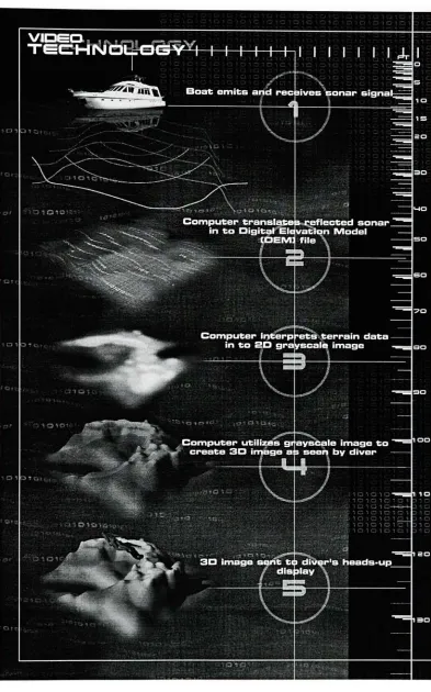
accomplished(see fig. 3).
1
.The
boat
emitsand receives sonar signals.Ultrasonic
technology
is
usedto
gatherinformation
ofthe
terrainunderneath.The
sonar
is
emittedfrom
an ultrasonictransmitterattachedto the boat.
The
sonarwavestravel
to the bottom
and reflectback to
an ultrasonic receiveronthe boat.
2.
A
computertranslatesthe
reflected sonarto
aDigital Elevation Model
(DEM)
file.
The
reflectedultrasonic signalfrom the bottom
is
sentto
a computerunitin
orderto translate the
of
the
diver's
positionboth
vertically
andhorizontally.
3.
A
computerdeciphers
the
DEM file into
a grayscaleimage.
The information
ofthe
height
ofthe terrain
is interpreted into
atwo-dimensional,
grayscale
image.
The
grayscaleimage
representsthe
height
ofthe terrain in two dimensions
by
the
variation ofbrightness
anddarkness. The
higher the
terrain,
the brighter the image.
In
contrast,
the lower the
terrain,
the
darker the image.
4. A
computer convertsthe
grayscaleimage
to
athree-dimensional
image
as seenby
the
diver.
A
computertranslates the two-dimensional
image into
athree-dimensionalimage
determined
by
the
variationofbrightness
anddarkness.
The
three-dimensionalimage
canbe
displayed
as a wireframeimage representing
agridonthe
terrain.The
wireframeimage may
look confusing, but it
could allowthe diver to
judge
scale anddistance
more precisely.Another
option wouldbe
thatofapplying shading
to the
surface ofthe
terrainin
orderto
provide a realistic
looking
environment.A
computercan alsopositionthe location
ofthe diver
respectiveto the
bottom terrain
and calculate
the
perspective ofthe diver to
create a simulated view as seenby
the
diver.
5.
A
three-dimensionalimage
is
sentto the
diver's
heads-up
display.
The
image
wouldbe
sentto the diver
by
utilizing
an ultrasonic signalin different
frequencies.
The
ultrasonicreceiverattachedto the diver translates the
signalinto
animage
projected
through VRD. Two VRD
projectorunits areattachedto the
sides ofthe
mask.Beams
oflights
aredirected from VRD
projectorsto the
lenses
andthen reflectedto the
retinas of
the diver.
Safety
ofdiving,
navigation underthe water,
andthe
complexity
of manualdive
tables
and
planning
problems aresolvedby
using
adive
computer.Existing
dive
computerfunctions
such as adigital
pressuregauge, watch,dive
table,
personaldiving
record,
thermometer,
and compass arecombinedin
one unitthe
size of a watch.This device
wouldalert
the diver automatically
whenthe he
or she needsto
recognizeany
conditionIDEATION
The design
wouldfeature
compactness,
durability,
low
powerconsumption,
video andaudio
technologies,
ergonomics, comfort,
ease ofuse, safety,
and streamline shape.Due to
the
amountofdiving
gearthat
adiver
needsto carry,
integration
of equipment neededto
be
considered.
Integrating
equipmentin
one unit might reducethe
complexity
of usage.Generally,
this
equipmentis
comprised of amask,
communicationunit,
visual simulationunit,
and
dive
computer unit.All
ofthe
electronic components wouldbe designed
to
be
containedwithin a closed shell
in
orderto
avoid moisture.Materials
that
wouldbe
chosen wouldhave
water
resistance,
goodimpact strength,
and good sunlight resistance.Polyvinyl
Chloride
would provide admirable qualities
for the
mask.A
silicone rubbersealing
edge couldbe
applied
to the
sealin
orderto
provideflexibility
and comfortto the
mask whereit
pressesto
the
diver's face.
Locations
ofcomponents were consideredin light
oftheiraccessibility
to the
diver
(see
fig. 4).
The
productitself
shouldbe constantly
attachedto the
diver's
body
whilediving.
The
personaldiving
assistanttoolshouldfit the
diver's
body
well.An
adjustablejoint is
necessary
for the diver to
customizethe
device
for
personal use.This
product shouldbe
effortless
to don
and operate.The design is focused
onreducing
the
complexity
ofdiving
preparation and performance.
This
productwouldfunction
chiefly
as amask.Other
features
couldbe
turned
on andoff
arbitrarily
by
the
user.The
design
ofthe
mask wasoriginally
concerned with ease of use.The
diver
coulddon it conveniently
withoutstruggling
withthe
resilientstrap,
as on anordinary
diving
mask.A helmet
is
asatisfactory
solutionfor
ease of use.All the
user needsto
do is
don the
mask and use a singlehand to
closethe
shield.The
diving
mask wouldbe
moreconvenient
to
putonif it
usedthe
same approach.In
contrastto
ahelmet,
the
diving
mask would not
be
openedby
using
a singlehand
or singlebutton
operation.The
diver
mightTherefore,
releasing
the
maskshouldbe
controlledby
using both hands. For
the
sake ofsafety,
releasing
by
turning
aknob
would workbetter than
pressing
abutton.
Moreover,
the
helmet
shouldbe
accessibleto
otherpersons such asthe
diver's
buddy
and crew members.The diver's
buddy
should alsohave
accessto
operatethe
mask when a problemstrikes,
suchas
"air
free
flow,""out
ofair,"
"share
air,"or
"unconscious
diver."For this
reason,the
regulatormouth piece connected
to the mask,
andthe
maskitself,
shouldbe
ableto
be
discharged
effortlessly.
The
shapeis derived
from
ergonomicfactors,
andhas
been
developed
to
representthe
metaphorofunderwater creatures(see
fig. 5-40).
The
development
of shape andform
is
also concerned with
accommodating
all ofthe
electronic components within.Moreover,
the
location
of allcomponentsshouldnotobstructthe
visualability
ofthe diver.
Thus,
the
battery
housing
andthe
centralprocessing
unit,
which require alarge
space, arelocated
atthe back
of
the helmet.
Positioning
the
battery
housing
andCPU
unit atthe back
furthermore
enhances
the ability
ofthedfver to
controlbalance
underwater.The VRD is
attachedto
theside within
the
mask.Operating
buttons
arelocated
onboth
sides ofthe
mask.Accessibility
from both
sidesis
usefulfor both right
andleft handed
persons.The lens is
wide enoughto
CHAPTER
4
PRESENTATION
The
concept ofthe
personaldiving
assistanttool
is
a complicated oneto
present.The
goal of
the
presentation wasto
explainthe
conceptby
providing
the
audiencewith avirtualexperience of
the
product's usebefore
the
productis
produced.This
wouldhelp
audiencesand
the designer to
understandthe
design
moreclearly.My
presentationincludes
concepts,
technologies,
usages,details,
and variations.In
creating
the
presentation,I
used a computerto
generateillustrations
both
animated and non-animated.In
orderto
accomplishmy
goal,
2D
digital
imaging,
2D animation, 3D
modeling,sound editing, and videoediting
softwarewererequired.
The
2D digital
image
programs,Adobe
Photoshop
andAdobe
Illustrator,
werethe
tools
usedfor
creating
still2D
text,
images,
and graphics.Adobe After
Effects,
2D
animationsoftware,was used
in compositing moving
texts,
graphics, anddescriptions in the
movie.The
3D
modeling
softwares used wereAlias/Wavefront,
Bryce
3D,
andPoser. Alias/Wavefront
allows
the designer to
experiment withlights,
shadings, shapes, andforms
ofthe
productfrom different
angles.Bryce 3D is
atoolfor generating
artificialambiancein
orderto
providethe
simulatedenvironmentto the
audience.In
orderto
include the
rightproportionsofaface,
a
human
figure
from Poser
wasimported to Alias/Wavefront.
The
3D
animation softwares,Alias/Wavefront,
Bryce
3D,
andPoser,
helped
meto
showthe
possibilities ofhow to
operatethe
productin
asimulation.Sounds
addedinto
the
movie were editedin SoundEdit 1 6 in
orderto
givetheambiance of
technology
andthe underwaterworld.The
videoediting
software,Adobe
CHAPTER 5
CONCLUSION
Technology
Although,
the
personaldiving
assistanttool
wasdesigned
by
utilizing
acombination ofexisting
technologies,
the
visibility
enhancement equipmentis
stillin the
conceptual state.The
synthesis oftechnologies
for
virtual vision underthe
wateris
projectedfor the
very
nearfuture
whenthe
performance ofcomputer processors andtransferdata
ratesbecomes faster.
The
size ofthis
equipmentis
also another concern.The reliability
ofthe
product woulddepend
mainly
upon electronicintelligence. A
malfunctioning
ofthe
circuitmay
happen
and causedanger to the diver
while underthe
water.If the
powersupply
waslost
orthe
systemfailed to
operate,the
product would notbe
ableto
assistthe
diver
whenneeded, especially
whenthe visibility
conditions were poor.A
powerbackup
systemshouldbe
considered.Design
The
tail shapeattheback
ofthe helmet
may
causethe diver to
collideinto
objectsunderwater when
turning
around.The
tailshouldbe
shortened.Battery
andCPU
housings
may
needto be
movedslightly
up
towardthe
top
ofthe helmet.
Presentation
Since
the Aquanic
projectintegrates
newand complicatedtechnologies,
explaining
them to
anaudienceverbally
may
notbe
an effectivemanner.The
audiencemay
have
difficulties in visualizing
technologiesandapplications.To
enhancethe
visualization andunderstanding
ofthe
audience, anillustration
wouldbe
an effectivetool.The
more realisticthe
audience see astillimage,
but
can also perceivethe
productin different
viewsby
meansof computer animation.
This is
amatter ofdesigning
the
experiencebefore
designing
the
product.I
believe
designing
the
experienceis
anotherimportant
approachfor industrial design to
communicatewith
marketing
and engineering.Marketing
andengineering
could seethe
potential of aproduct
before
bringing
it to life.
The
purpose ofthis
is
to
simulatethe
use ofthe
product.Utilizing
multimedia as a simulation tool makesthe
presentationmore understandable andattractive.
On the
otherhand,
employing
multimediaas atool
is
atime
consuming
processwhich
may
notbe
acceptablein
some situations.Moreover,
producing
adesigned
experienceassumes skills of
using
softwares andtools.
The
designer
must combineindustrial design
>, CD
O O
c
-C
o
|2
o
<
CD
E
CO
o
'c TO CT <
CD
c
CD
c
o o. E o
o
-C o CO
0
c
o
ca o
o
J
0
0
h
h
2
<
h
Ifl
ui
in
<
ID
2
>
Q
it
<0
<
< c
co
Q. <D O
o
J
0
0
h
h
2
<
h
Ii)
Oi
in
<
ID
2
>
Q
ii
<0
Ol
<3-<
<
c
CO
CO <
Q. CD O c
o
O
c a>
c/>
0) Q
to
!?
J
0
0
h
h
2
<
in
in
m
<
ID
2
>
Q
ii
<0
Din
CD
<
CO < C co LO < Q. CD O C o o c 55 CO CD Q
0
0
h
h
2
<
h
in
in
in
<
ID
2
>
0
3i
OS
CO
<
r--<
CO <
C co
r--<
-^
Q. CD O C o o c
cp
CO
CD
Q
00
J
0
0
h
h
2
<
h
in
in
in
<
ID
2
>
D
ii
<0
X} c CO
CD
<
Q. CD O C o o
c O)
CO
CD
Q
J
0
0
h
h
2
<
h
m
in
in
<
ID
2
>
5
<o
a|
CM CD
cn
C\J CD
T3 C
CO
**
Q. CD
O C
o
o c O) CO
CD Q
0
0
h
h
2
<
in
in
in
<
ID
2
>
0
Zz
<0
3in
Offi
<(L
co
CD
CO
73 C CO
s
CD O c o o
c O) CO CD Q
J
0
0
>
h
2
<
h
in
in
in
<
ID
2
>
Q
it
<o
CD
CD
CD
00
~o c CO
LO
cn
+->
Q. CD O C o o
c O) co CD Q
C\j
J
0
0
h
\-2
<
in
in
in
<
ID
2
D
it
Din
o
CDco
CQ
o c CO r^
00
>
Q.
CD O
o
o c D)
CO
CD
Q
CO
J
0
0
h
h
2
<
h
in
in
in
<
ID
2
D
ii
3in
0&
<l
o
T
CD
o
"D C CO 05 00
-Q. 0 O c o o c g> co 0
Q
0
0
h
h
2
<
h
in
in
in
<
ID
2
Q
ii
<0
CM
o
CM
o
c: CO
O
- ' Q. 0
O c
o
o
c
O)
CO
0
Q
>v
J
0
0
h
h
2
<
h
m
in
in
<
ID
2
>
0
ii
jifl
5|
o
o
c CO CO
o
41 a. 0
o c
o o
c
?
co
0
Q
cb
2>
J
0
0
h
h
2
<
h
m
in
in
<
ID
2
>
0
CD
o
<o
0g
<l
^
LO
o
CD o a c CO
LO O
*-*
a. 0 o c o o c ai co 0 a
J
0
0
h
2
<
h
in
in
in
<
ID
2
>
5
Uj
Zf
<o
jin
Og
CO
O
^>
CO
O
-a c CO
O
*' D. 0 O c o o c gy co 0
Q
cci
CM
Q
T3 c CO
Q
* Q.
0
O C o o c g> co
0
Q
b
J
<3-Q
0
/
o
(
h
N
h
2
^^^r*f<
i*^^^^^^^h
S^in
>^ y^in
-in
/
a<
1v0
z
\
,
xV
>
f
<Q
1/
Uj
If
1
z!
ff
I
CD Q
o
c CO LO
Q +-< a. 0
o c
o
o c
CO
0
Q
c\i CM
?
J
0
0
h
h
2
<
h
m
in
in
<
ID
2
>
Q
ii
<0
al
r~-Q
K
Q
Q. 0
O c
o
o c 01 co 0
Q
CO CM
Q
J
0
0
h
H
2
<
h
in
in
in
<
ID
2
>
Q
it
<9
3in
al
<(L
Q
o c: CO
co
Q
Q. 0
O c
o
o c o>
CO 0
Q CM 5?
J
0
0
h
h
2
<
h
in
in
in
<
ID
2
>
Q
ii
<o
3in
al
<i
LU
LU
T3 C CO
Q. 0 O c
o
o c gi co
0
Q
LO CM
J
0
0
h
h
2
<
h
in
in
in
<
ID
2
>
Q
ii
<o
al
CO
LU
CO
LU
D C CO
CNJ
LU
-t
Q. 0 O C
o
o c g> co
0
Q
co CM
J
0
0
h
h
2
<
h
m
in
in
<
ID
2
>
0
it
Urn
<1
LU
LU
Q.
0
O c
o
o c O) CO
0
Q
n:
J
0
0
h
h
2
<
h
m
in
in
<
ID
2
>
6
ii
<o
al
LU
"D c CO CD
LU
LU
Q. 0
O c
o
o c O) CO 0
a
J
0
0
h
h
2
<
h
m
in
in
<
ID
2
>
5
zi
<o
81
<IL
o
LU
-a c CO cn
LU LU
?
Q. 0
O c
o
o c go
CO
0
Q
oS CM
J
0
0
>
2
<
h
in
in
in
<
ID
2
>
5
a
j\n
OS
co
LL
T3 C CO CM
LL
Q. 0 cj C o O c
P
co
0
Q
d
CD
U_
J
0
0
h
h
2
<
h
in
in
in
<
ID
2
>
Q
it
<o
al
CD
LL
"O c co LO
2
Q.
0
O C
o
o c Ol co
0 Q
CO
J
0
0
h
h
2
<
h
in
in
in
<
ID
2
Q
ii
<0
3U1
al
cr>
LL
C co CO
Q.
0
o c
o
o c O) co
0
Q
CM
CO
J
0
0
h
h
2
<
h
m
in
in
<
ID
2
Q
ii
<o
3in
al
CM
CD
T3 C CO
O
Q.
0
O c o o
c at CO 0
Q
CO co
J
0
0
h
h
2
<
h
m
in
in
<
ID
2
>
0
ii
3in
al
<l
LO
o
c CO
CD
co
CD
+-Q.
0
O C o o c Ul
CO
0
Q
CO
*3?
J
0
0
h
h
2
<
h
in
in
in
<
ID
2
>
5
ii
<0
3in
al
CO
CD
D
c co h~
(3
CD
-?>CL
0
O c
o
o c cn CO
0
Q
LO CO
J
0
0
h
h
2
<
h
in
in
in
<
ID
2
>
5
ii
<o
3D1
al
T3 C CO
o
CD
CD
ji*
Q.
0
O c
o
o
c:
co 0 Q
cb
CO
-J
0
0
h
h
2
<
h
in
in
in
<
ID
2
Q
it
3in
OS
X
"O C CO
CO
X
X
Q. 0 o c
o
o
c O)
CO
0
Q
co
!?
J
0
0
h
h
2
<
h
m
in
in
<
ID
2
>
D
it
<o
3i
al
LO
I LO
X
Q.
0
O c
o
o c O) to
0 Q
od co 05
J
0
0
h
h
2
<
h
m
in
in
<
ID
2
>
Q
ii
<o
3in
al
<i
CD
X
CD
X
Q.
0
O c
o
CJ
c
O)
co
0
Q
oS co