INVESTIGATIONS ON LOW-VALENT GROUP 8 AND 9
METALLORADICALS
Thesis by Ayumi Takaoka
In Partial Fulfillment of the Requirements for the Degree of Doctor of Philosophy
California Institute of Technology Pasadena, CA
2012
© 2012
Ayumi Takaoka
Acknowledgments
I would like to first and foremost thank my research advisor, Professor Jonas C.
Peters, for taking me into his group in 2007 and advising me throughout my graduate
career. In addition to being a truly brilliant principle investigator, Jonas has always been
incredibly patient in teaching me the fundamental process of research, and I am
extremely grateful for this. As previous graduates of this research group have also stated,
much of my scientific thought process operates according to how I believe Jonas would
proceed in solving difficult problems. Indeed, I believe that I have been able to conduct
research most efficiently by thinking about the types of questions Jonas would ask during
our group meetings. Simply put, I could not have asked for a better advisor. Jonas also
gave me the opportunity to pursue my graduate studies at two of the best research
institutions in the world, for which I feel very fortunate. This unique experience gave me
a chance to work at two very distinct environments and provided me with the confidence
in taking an industrial position in Japan, which is a place where I have not lived for over
13 years and expect to be quite different from both MIT and Caltech.
Professors Dick Schrock and Theo Agapie were the chairs of my thesis committee
at MIT and Caltech, respectively. Dick was always supportive of the chemistry I was
pursuing at MIT, and was especially excited about the dinitrogen complexes that I was
synthesizing at the time. He was always available for scientific discussion, and he even
spent time with me for our annual thesis chair meeting before our group left for Caltech,
even through he no longer had any obligations to do so. Theo was also very supportive of
my research at Caltech and was a great thesis chair to have. His criticism was extremely
content. Many of the questions that he raised during our meetings helped me think more
deeply about my research. Theo also happens to be married to one of my very good
friends, Smaranda, and was kind enough to invite me to their wedding. I wish the best to
both Theo and Smaranda in the future. Other members of my two committees, Professors
Steve Lippard at MIT and Harry Gray and Mitchio Okumura at Caltech, were also
instrumental in providing me with great advice through the years.
I owe a tremendous amount to my classmates, Samantha MacMillan, Seth
Mickenberg, Daniel Suess, and Charlene Tsay, who joined the Peters group with me in
2007. Each and every member of this group has been a great friend and has helped me
keep my sanity through tough times. I will greatly miss them. I have also been fortunate
to overlap with a large number of brilliant co-workers. I would like to name a few in
detail that have particularly been helpful. Aside from Jonas, Dr. Neal Mankad probably
influenced my approach to research the most, and I am honored to coauthor a publication
with him. He also introduced me to fantasy football, which has been one of my favorite
pastimes outside of research. Dr. Arjun Mendiratta and Laura Gerber also coauthored
publications with me. Professor Yunho Lee was an incredible boxmate who taught me
many experimental techniques. Dr. Marc-Etienne Moret was one of my best sources of
chemical knowledge, and was also a great lunch buddy. Kenny Lotito and Jon Rittle were
my other boxmates who had to endure my presence while conducting research inside the
glovebox. Dr. Hill Harman, Alicia Chang, and Henry Fong are friends from my
undergraduate research group, and I will miss not seeing them everyday. John Anderson
was my fantasy football rival and was kind enough to invite me to his residence for
Professor Nate Sczymczak, Professor Louise Berben, Dr. Ning Jin, Dr. Caroline Sauoma,
Dr. Chris Uyeda, Dr. Charles McCrory, and Sid Creutz.
I could not have performed my research without the competence of the technical
staff at both MIT and Caltech. Dr. Peter Müller and Larry Henling were the X-ray
crystallographers that helped me at the two institutions, respectively. Dr. Jeff Simpson,
Anne Gorham, and Dr. David Vandervelde were staff at the NMR facilities and were
always helpful in setting up NMR experiments that were beyond my understanding. Dr.
Angelo DiBilio taught me how to measure an EPR spectrum.
I have been very fortunate to be surrounded by a great group of friends outside the
Peters group at both MIT and Caltech. Julia Kozhukh and Shuang Liu were my friends at
MIT, and I wish the best for both of them in their future. Rachel Klet was a person I first
met at the Caltech visiting weekend, and she introduced me to numerous delicious
cuisines throughout this area. Hidehiko Inagaki, Akihisa Goban, and Taisuke Imai are
members of the Japanese community at Caltech whom I have had a great time with. In
addition to these people, countless others have been kind and helpful to me.
I would also like to thank the entire MIT and Caltech community. Both
institutions were incredible research environments. In fact, I had such a nice time at MIT
that I was somewhat hesitant to move from Cambridge to Pasadena because I thought it
could only get worse. I am fortunate that I was wrong and that the Caltech community as
a whole has been extremely welcoming and friendly.
Finally, I could not have accomplished anything that I have these past few years
Takaoka. I look forward to living closer to my family in the coming years. Last but not
least, I am indebted to Hazuki Nakatani for providing moral support over the years.
The past few years have been absolutely incredible. This experience will probably
Abstract
Tetradentate, monoanionic, tris(phosphino)silyl ligands were chelated to group 8
and 9 transition metals to stabilize complexes with unusual oxidation states and/or
geometries. Initial studies with the [SiPPh3]− ligand on ruthenium established the
flexibility of this ancillary ligand in stabilizing complexes with strongly trans influencing
ligands in trans dispositions. A related ligand scaffold, [SiPiPr3]−, was subsequently used
to stabilize mononuclear complexes of Ru(I) and Os(I), the first examples to be isolated
and thoroughly chracterized. EPR spectroscopy and DFT calculations supported their
metalloradical character, and further studies highlighted their reactivity in both one- and
two-electron redox processes. The ability of the [SiPiPr3]− scaffold to stabilize d7
metalloradicals of group 8 metals was extended to group 9 metals, and a series of d7 complexes of cobalt, rhodium, and iridium were synthesized in which their ancillary
ligands, oxidation states, spin states, and geometry are conserved. Similar to the
previously reported [SiPiPr3]Fe(N2) complex, the related [SiPiPr3]Ru(N2) complex was
shown to exhibit N−N coupling of organic azides to yield azoarenes catalytically.
Detailed mechanistic studies conclusively showed that the Ru(III) imide species, whose
iron analog is the key intermediate in the [SiPiPr3]Fe system, is not involved in the
mechanism for the [SiPiPr3]Ru system. Instead, a mechanism in which free nitrene is
released during the catalytic cyle is favored. Finally, hybrid ligands with multiple
thioether donors in place of phosphine donors on the [SiPR3]− scaffold were synthesized
to stabilize a number of dinitrogen complex of iron. These complexes featured rare
Table of Contents
Acknowledgments ... iii
Abstract ... vii
Table of Contents ... viii
List of Figures ... xii
List of Tables ... xvii
List of Abbreviations ... xix
Chapter 1: Introduction ... 1
1.1 Opening Remarks... 2
1.2 The Tris(phosphino)silyl Ligand ... 5
1.3 d7 Complexes of Group 8 and 9 ... 6
1.4 Reactivity of a Ru(I) Metalloradical ... 7
1.5 Hybrid Phosphine/Thioether Ligands ... 9
References Cited ... 12
Chapter 2: E-H Bond Activation Reactions (E = H, C, Si, Ge) at Ruthenium: Terminal Phosphides, Silylenes, and Germylenes ... 14
2.1 Introduction ... 15
2.2 Results and Discussion ... 16
2.2.1 Alkyl and Phosphide Complexes ... 16
2.2.2 Silane, Silylene, and Germylene Complexes ... 22
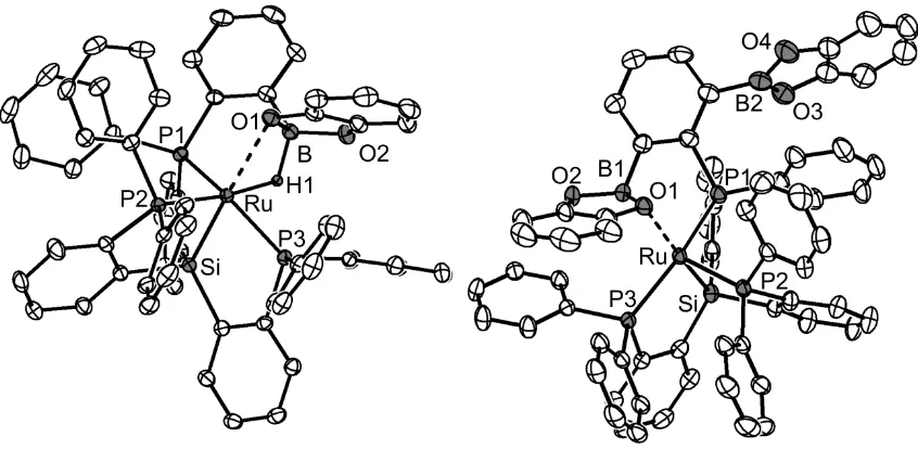
2.2.3 Attempts to Synthesize Boryl Complexes ... 30
2.3 Conclusion ... 32
2.4 Experimental Section ... 32
2.4.1 General Considerations ... 32
2.4.2 X-ray Diffraction Details ... 33
2.4.3 Spectroscopic Measurements ... 34
2.4.4 Kinetic Measurements ... 34
2.4.6 Synthesis ... 35
References Cited ... 45
Chapter 3: Access to Well-Defined Ruthenium(I) and Osmium(I) Metalloradicals ... 50
3.1 Introduction ... 51
3.2 Results and Discussion ... 52
3.3 Conclusion ... 59
3.4 Experimental Section ... 60
3.4.1 General Considerations ... 60
3.4.2 X-ray Crystallography Procedures ... 61
3.4.3 Spectroscopic Measurements ... 61
3.4.4 Electrochemistry ... 62
3.4.5 DFT Calculations ... 62
3.4.6 Synthesis ... 64
References Cited ... 73
Chapter 4: A Homologous Series of Cobalt, Rhodium, and Iridium Metalloradicals ... 79
4.1 Introduction ... 80
4.2 Results and Discussion ... 81
4.3 Conclusion ... 88
4.4 Experimental Section ... 89
4.4.1 General Considerations ... 89
4.4.2 X-ray Crystallography Procedures ... 89
4.4.3 Electrochemistry ... 90
4.4.4 DFT Calculations. ... 90
4.4.5 Other Spectroscopic Measurements ... 91
4.4.6 Synthesis ... 92
References Cited ... 96
Chapter 5: Catalytic N-N Coupling of Aryl Azides to Yield Azoarenes with a Ru(I) Metalloradical ... 100
5.2. Results and Discussion ... 104
5.2.1 Reaction between 5.4 and p-MeOC6H4N3 and Other Aryl Azides ... 104
5.2.2 A Strategy Towards the Synthesis of 5.5-OMe ... 106
5.2.3 Solid-State Structures of 5.8-OMe, 5.7-OMe, and 5.10 ... 110
5.2.4 Synthesis of 5.5-OMe and Mechanistic Studies ... 112
5.2.5 Considering the Release of Free Aryl Nitrene. ... 114
5.2.6 EPR Spectroscopy on 5.5-R and 5.10-R... 118
5.2.7 DFT Calculations on 5.5-OMe and 5.11-OMe. ... 121
5.2.8 Electronic Structure of 5.7-OMe ... 125
5.3. Mechanistic Considerations ... 127
5.4. Conclusions ... 130
5.5. Experimental Section ... 130
5.5.1 General Considerations ... 130
5.5.2 Crystallographic Details ... 131
5.5.3 Electrochemical Details ... 132
5.5.4 Synthetic Details ... 132
5.5 References Cited. ... 139
Chapter 6: Dinitrogen Complexes of Sulfur-Ligated Iron ... 144
6.1 Introduction ... 145
6.2 Results and Discussion ... 146
6.3 Conclusion ... 153
6.4 Experimental Section ... 154
6.4.1 General Considerations ... 154
6.4.2 X-ray Crystallography Procedures ... 154
6.4.3 SQUID Measurements ... 155
6.4.4 Spectroscopic Measurements ... 155
6.4.5 Electrochemistry ... 155
6.4.6 DFT Calculations ... 156
6.4.7 Synthesis ... 156
Appendix 1: Supplementary Data for Chapter 2 ... 175
Appendix 2: Supplementary Data for Chapter 3 ... 179
Appendix 3: Supplementary Data for Chapter 4 ... 208
Appendix 4: Supplementary Data for Chapter 5 ... 220
List of Figures
Chapter 1 ... 1
Figure 1.1. (Left) The [SiPR3]− class of ligands. (Right) A generic metal complex, [SiP R 3]MX, where X is a ligand trans to the silyl anchor. ... 5
Figure 1.2. Example model complexes of the generic formula [SiPiPr3]Fe(NxHy). ... 9
Figure 1.3. Hypothetical binding mode of N2 at the FeMoco (left) and a hypothetical model complex (right). ... 10
Chapter 2 ... 14
Figure 2.1. Left: Solid-state structure of 2.1. Right: Solid-state structure of 2.3. ... 18
Figure 2.2. Left: Solid-state structure of 2.5. Right: Solid-state structure of 2.6. ... 19
Figure 2.3. Left: Solid-state structure of 2.10a. Right: LUMO of 2.10a. ... 25
Figure 2.4. Solid-state structure of 2.11. ... 27
Figure 2.5. Left: 1H NMR (300 MHz) of the hydride resonance of 2.8 at RT. ... 29
Figure 2.6. Left: Solid-state structure of 2.14. Right: Solid-state structure of 2.15. ... 31
Chapter 3 ... 50
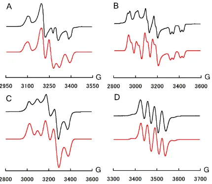
Figure 3.1. a) EPR specrum of 3.3 (77 K). b) EPR specrum of 3.4 (77 K). c) EPR specrum of 3.5 (77 K). d) EPR specrum of 3.11 (RT).. ... 55
Figure 3.2. Solid-state structures and spin density plots for 3.3 (top) and 3.11 (bottom). ... 56
Chapter 4 ... 79
Figure 4.1. Solid-state structures of {[SiPiPr3]M(PMe3)}{BAr F 4} (M = Co (4.1, top left), Rh (4.2, bottom)) and {[SiPiPr3]Ir(PMe3)}{OTf} (top right). ... 83
Figure 4.2. Spin density plots (left) and X-Band 77 K EPR spectra (right) in 2-MeTHF of 4.1 (top), 4.2 (center), and 4.3 (bottom). ... 85
Chapter 5 ... 100
Figure 5.1. Key compounds involved in this work. ... 104
Figure 5.2. Solid-state structure of 5.8-OMe (left), 5.7-OMe (right), and 5.10 (bottom). ... 109
Figure 5.4. X-Band EPR spectra of triplet p-tolyl nitrene (red) and triplet p-methoxyphenyl
nitrene (blue). ... 115
Figure 5.5. A, B: EPR spectra of 5.5-CF3 (A: RT, B: 77 K). C, D: EPR spectra of 5.5-OMe (C: RT, D: 77 K). E: 77 K EPR spectrum of 5.11-OMe. F: 77 K EPR spectrum of 5.11-CF3. G: 77 K EPR spectrum of 5.12. ... 117
Figure 5.6. (Left) RT EPR spectrum of crude mixture from reaction between 5.4 and tolylazide. (Right) Contribution of 5.4 (red) and 5.5-Me (blue) to crude spectrum. ... 119
Figure 5.7. Decay of 5.11-CF3to 5.5-CF3. Black curve, 5.11-CF3. Red Curve, 5.5-CF3.. ... 121
Figure 5.8. First-order decay plot of 5.11-CF3 (3.4 mM) in 2-MeTHF at −76 °C. ... 121
Figure 5.9. DFT optimized structure of 5.5-OMe (left) and spin density plot (right). ... 122
Figure 5.10.Energies of DFT optimized structures of 5.11-OMe... 122
Figure 5.11. (Left) Core atoms of 5.7-OMe with relevant bond lengths (Å) and angles (°). (Right) MO diagram of 5.7-OMe obtained from a single point calculation on X-ray coordinates. ... 124
Figure 5.12. A comparison of [TPB]Fe(NAr) with 5.7-OMe. ... 126
Chapter 6 ... 144
Figure 6.1. Hypothetical binding mode of N2 at the FeMoco (left) and a hypothetical model complex (right). ... 146
Figure 6.2. Solid-state structures of 6.10 and 6.13 (50% probability; H atoms and solvent for 6.10 and 6.13, BArF4− for 6.10 removed). ... 149
Appendix 1 ... 175
Figure A1.1. 1H−29Si HSQC spectrum of 2.13 of upfield peak in d8-THF. ... 176
Figure A1.2. Eyring plot for the decay of 2.5. ... 177
Figure A1.3. Typical decay behavior of 2.5 vs d30-[SiP Ph 3]Ru(PPh2) at 35°C. ... 178
Appendix 2 ... 179
Figure A2.1. Solid-state structure of [SiPiPr3]RuN2 (3.3). ... 182
Figure A2.2. Solid-state structure of [SiPiPr3]OsN2 (3.4). ... 184
Figure A2.3. Solid-state structure of [SiPiPr3]Ru(PMe3) (3.5). ... 186
Figure A2.4. Solid-state structure of {[SiPiPr3]Ru(N2)} + BArF4 (3.7). ... 188
Figure A2.5. Solid-state structure of 3.7 from a crystal grown under different conditions. ... 188
Figure A2.7. Solid-state structure of {[SiP 3]Os(N2)}K (THF)2 (3.9). ... 192
Figure A2.8. Solid-state structure of [SiPiPr3]Ru(H)(N2) (3.10). ... 194
Figure A2.9. Solid-state structure of [SiPiPr3]Ru(NAr) Ar = p-C6H4CF3 (3.11). ... 196
Figure A2.10. Solid-state structure of [SiPiPr3]Os(NAr) Ar = p-C6H4CF3 (3.12). ... 198
Figure A2.11. CV of [SiPiPr3]RuCl (3.1) (50 mV/s). ... 199
Figure A2.12. CV of [SiPiPr3]OsCl (3.2) (50 mV/s). ... 199
Figure A2.13. CV of [SiPiPr3]RuN2 (3.3) (100 mV/s). ... 200
Figure A2.14. CV of {[SiPiPr3]RuN2} + BArF4 (3.7) (100 mV/s). ... 200
Figure A2.15. CV of [SiPiPr3]OsN2 (3.4) (50 mV/s). ... 201
Figure A2.16. X-band RT EPR spectrum of [SiPiPr3]RuN2 (3.3) in toluene glass (red line: simulation). ... 202
Figure A2.17. X-band 77K EPR spectrum of [SiPiPr3]RuN2 (3.3). ... 202
Figure A2.18. X-band RT EPR spectrum of [SiPiPr3]OsN2 (3.4) in toluene glass (red line: simulation). ... 203
Figure A2.19. X-band 77K EPR spectrum of [SiPiPr3]Os(N2) (3.4). ... 203
Figure A2.20. X-band RT EPR spectrum of [SiPiPr3]Ru(PMe3) (3.5) in toluene glass (red line: simulation). ... 204
Figure A2.21. X-band 77K EPR spectrum of [SiPiPr3]Ru(PMe3) (3.5). ... 204
Figure A2.22. X-band RT EPR spectrum of [SiPiPr3]Os(PMe3) (3.6) in toluene glass (red line: simulation). ... 205
Figure A2.23. X-band 77K EPR spectrum of [SiPiPr3]Os(PMe3) (3.6). ... 205
Figure A2.24. X-band RT EPR spectrum of [SiPiPr3]Ru(NAr) Ar = p-C6H4CF3 (3.11) in toluene glass. ... 206
Figure A2.25. X-band EPR spectrum of [SiPiPr3]Ru(NAr) Ar = p-C6H4CF3 (3.11) in toluene glass at 77 K. ... 206
Figure A2.26. X-band RT EPR spectrum of [SiPiPr3]Os(NAr) Ar = p-C6H4CF3 (3.12) in toluene glass. ... 207
Figure A2.27. X-band EPR spectrum of [SiPiPr3]Os (NAr) Ar = p-C6H4CF3 (3.12) in toluene glass at 77 K. ... 207
Appendix 3 ... 208
Figure A3.1. Solid-state Structure of {[SiPiPr3]Co(PMe3)}BAr F 4 (4.1). ... 210
Figure A3.2. Solid-state Structure of {[SiPiPr3]Rh(PMe3)}BAr F 4 (4.2). ... 212
Figure A3.4. 77 K EPR spectrum of {[SiP 3]Co(PMe3)}BAr 4 (4.1). ... 215
Figure A3.5. RT EPR spectrum of {[SiPiPr3]Rh(PMe3)}BAr F 4 (4.2). ... 216
Figure A3.6. 77 K EPR spectrum of {[SiPiPr3]Rh(PMe3)}BAr F 4 (4.2). ... 216
Figure A3.7. RT EPR spectrum of {[SiPiPr3]Ir(PMe3)}BAr F 4 (4.3). ... 217
Figure A3.8. 77 K EPR spectrum of {[SiPiPr3]Ir(PMe3)}BArF4 (4.3)... 217
Figure A3.9. Cyclic Voltammogram of {[SiPiPr3]Co(PMe3)}BAr F 4 (4.1). ... 218
Figure A3.10. Cyclic Voltammogram of [SiPiPr3]Rh(PMe3) (4.2). ... 218
Figure A3.11. Cyclic Voltammogram of [SiPiPr3]Ir(PMe3) (4.3). ... 219
Appendix 4 ... 220
Figure A4.1. Solid-state structure of {[SiPiPr3]Ru(NAr)}OTf (Ar = C6H4CF3, 5.7-CF3). ... 222
Figure A4.2. Solid-state structure of {[SiPiPr3]Ru(NAr)}OTf (Ar = C6H4OMe, 5.7-OMe). ... 224
Figure A4.3. Solid-state structure of {[SiPiPr3]Ru(N3Ar)}BAr F 4 (Ar = C6H4OMe, 5.8-OMe). .. 226
Figure A4.4. Solid-state structure of {[SiPiPr2P iPr (=NAr)]Ru}PF6 (Ar = C6H4OMe, 5.10). ... 228
Figure A4.5. RT EPR spectrum of [SiPiPr3]Ru(NAr), Ar = p-C6H4OMe (5.5-OMe). ... 229
Figure A4.6. 77 K EPR spectrum of [SiPiPr3]Ru(NAr), Ar = p-C6H4OMe (5.5-OMe) ... 229
Figure A4.7. RT EPR spectra of crude mixture (left) of stoichiometric reaction between [SiPiPr3]Ru(N2) (5.4) and p-MeOC6H4N3 and after subtraction of 5.4 (right). ... 230
Figure A4.8. RT EPR spectra of crude mixture (left) of stoichiometric reaction between [SiPiPr3]Ru(N2) (5.4) and p-EtOC6H4N3 and after subtraction of 5.4 (right). ... 230
Figure A4.9. RT EPR spectra of crude mixture (left) of stoichiometric reaction between [SiPiPr3]Ru(N2) (5.4) and MeC6H4N3 and after subtraction of 5.4 (right). ... 231
Figure A4.10. RT EPR spectra of crude mixture (left) of stoichiometric reaction between [SiPiPr3]Ru(N2) (5.4) and MesN3 and after subtraction of 5.4 (right). ... 231
Figure A4.11. 77K EPR spectrum of [SiPiPr3]Ru(N3Ar), Ar = p-C6H4OMe (5.11-OMe). ... 232
Figure A4.12. 77K EPR spectrum of [SiPiPr3]Ru(N3Ar), Ar = p-C6H4CF3 (5.11-CF3). ... 232
Figure A4.13. Cyclic Voltammogram of [SiPiPr3]Ru(NAr), Ar = p-C6H4CF3, (5.7-CF3). ... 233
Figure A4.14. DFT optimized structure of γ (top left), α (top right), and η2 bound azide adducts (bottom), [SiPiPr3]Ru(N3Ar) (Ar = C6H4OMe) (5.11-OMe). ... 234
Appendix 5 ... 247
Figure A5.1. Solid-state structure of [SiPiPr2S Ad ]FeCl. ... 249
Figure A5.2. Solid-state structure of {[SiPiPr2S Ad ]Fe(N2)}BAr F 4 (6.10). ... 251
Figure A5.4. Solid-state structure of {[SiP 2S]Fe}2. ... 255
Figure A5.5. Solid-state structure of [SiPiPrSAd2]Fe(H)(N2) (6.13). ... 257
Figure A5.6. EPR spectrum of {[SiPiPrSAd2]Fe}2(N2)}BAr F
4 (6.14). (20K in 2-MeTHF) ... 258
Figure A5.7. EPR spectrum of {[SiPPhSAd2]Fe}2(N2)}BAr F
4 (6.15). (20K in 2-MeTHF) ... 258
Figure A5.8. NIR spectrum of {[SiPiPrSAd2]Fe}2(N2)}BAr F
4 (6.14). (ε (M -1
cm-1) vs wavelength (nm)) ... 259 Figure A5.9. NIR spectrum of {[SiPPhSAd2]Fe}2(N2)}BAr
F
4 (6.15). (ε(M -1
List of Table
Chapter 4 ... 79
Table 4.1. EPR parameters for complexes, 4.1-4.3 and 4.11, 4.12. ... 86
Table 4.2. Mulliken spin densities from DFT calculations ... 87
Chapter 5 ... 100
Table 5.1. Yield (%) of ArNNAr from 5.4 from one equivalent of substituted ArN3. ... 106
Table 5.2. Comparison of Ru−Si bond lengths (Å) and sum of P−Ru−P angles (°) for representative 5-coordinate Ru(I) and Ru(II) complexes relative to 7-OMe. ... 111
Appendix 1 ... 175
Table A1.1. Kinetic data for Eyring plot. ... 177
Appendix 2 ... 179
Table A2.1. Spin densities calculated from optimized and solid-state structures. ... 180
Table A2.2. Crystal data and structure refinement for [SiPiPr3]RuN2 (3.3). ... 181
Table A2.3. Crystal data and structure refinement for [SiPiPr3]OsN2 (3.4). ... 183
Table A2.4. Crystal data and structure refinement for [SiPiPr3]Ru(PMe3) (3.5). ... 185
Table A2.5. Crystal data and structure refinement for {[SiPiPr3]Ru(N2)} + BArF4 (3.7) ... 187
Table A2.6. Crystal data and structure refinement for {[SiPiPr3]Ru(N2)} -K+(THF)2 (3.8). ... 189
Table A2.7. Crystal data and structure refinement for {[SiPiPr3]Os(N2)} -K+(THF)2 (3.9). ... 191
Table A2.8. Crystal data and structure refinement for [SiPiPr3]Ru(H)(N2) (3.10). ... 193
Table A2.9. Crystal data and structure refinement for [SiPiPr3]Ru(NAr) Ar = p-C6H4CF3 (3.11).195 Table A2.10. Crystal data and structure refinement for [SiPiPr3]Os(NAr) Ar = p-C6H4CF3 (3.12).197 Appendix 3 ... 208
Table A3.1. Crystal data and structure refinement for {[SiPiPr3]Co(PMe3)}BAr F 4 (4.1). ... 209
Table A3.2. Crystal data and structure refinement for {[SiPiPr3]Rh(PMe3)}BAr F 4 (4.2). ... 211
Appendix 4 ... 220 Table A1.1. Crystal data and structure refinement for {[SiPiPr3]Ru(NAr)}OTf (Ar = C6H4CF3,
5.7-CF3). ... 221
Table A4.2. Crystal data and structure refinement for {[SiPiPr3]Ru(NAr)}BAr F
4 (Ar = C6H4OMe, 5.7-OMe). ... 223 Table A4.3. Crystal data and structure refinement for {[SiPiPr3]Ru(N3Ar)}BArF4 (Ar = C6H4OMe,
5.8-OMe). ... 225 Table A4.4. Crystal data and structure refinement for {[SiPiPr2P
iPr
(=NAr)]Ru}PF6 (Ar =
C6H4OMe, 5.10). ... 227
Table A4.5. DFT optimized coordinates of γ-bound azide adduct, [SiPiPr
3]Ru(N3Ar) (Ar =
C6H4OMe) (5.11-OMe). ... 235
Table A4.6. DFT optimized coordinates of α -bound azide adduct, [SiPiPr
3]Ru(N3Ar) (Ar =
C6H4OMe) (5.11-OMe). ... 238
Table A4.7. DFT optimized coordinates of (α,β)-N η2
-bound azide adduct, [SiPiPr3]Ru(N3Ar) (Ar
= C6H4OMe) (5.11-OMe). ... 241
Table A4.8. DFT optimized coordinates of (β,γ)-N η2
-bound azide adduct, [SiPiPr3]Ru(N3Ar) (Ar
= C6H4OMe) (5.11-OMe). ... 244
Appendix 5 ... 247 Table A5.1. Crystal data and structure refinement for [SiPiPr2S
Ad
]FeCl. ... 248 Table A5.2. Crystal data and structure refinement for {[SiPiPr2S
Ad
]Fe(N2)}BAr F
4 (6.10). ... 250
Table A5.3. Crystal data and structure refinement for {[SiPiPr2S Ad
]Fe(Cp). ... 252 Table A5.4. Crystal data and structure refinement for {[SiPiPr2S]Fe}2. ... 254
List of Abbreviations
Ad 1-Adamantyl
Anal Analysis
Ar Generic aryl group
ArF 3,5-(CF3)C6H3
ArN=NAr Azoarene
atm Atmosphere
br Broad
calcd Calculated
cat Catecholate
CCD Charge-coupled device
cm Centimeter
cm−1 Wave number
COD Cyclooctadiene
Cp Cyclopentadienyl
Cp* Pentamethylcyclopentadienyl
CV Cyclic voltammetry
Cy Cyclohexyl
d Doublet or deuterium
D deuterium
dx d-electron count of x
dx Compound with x deuterium atoms
deg Degree
DFT Density Functional Theory
dtbpe 1,2-Bis(di-tert-butylphosphino)ethane
E Generic main-group element
e Electron
EPR Electron paramagnetic resonance
equiv Equivalents
esp α,α,α’,α’-tetramethyl-1,3-benzenedipropionate
eu Entropy units
Et Ethyl
F Structure factor
Fc Ferrocene
FeMoco Iron-Molybdenum cofactor
G Gauss
g Gram
g g-factor
giso Isotropic g-factor
gmax Maximum anisotropic g-tensor
gmin Minimum anisotropic g-tensor
GHz Gigahertz
HOMO Highest occupied molecular orbital
Hz Hertz
Inc Incorporated
iPr iso-Propyl
IR Infrared
ISC Intersystem crossing
J NMR coupling constant
Jxy NMR coupling constant between nuclei x and y
K Kelvin
Kcal Kilocalorie
KIE Kinetic isotope effect
L Generic neutral ligand
LUMO Lowest unoccupied molecular orbital
M Generic transition metal or molar
m Multiplet
m meta
Me Methyl
Mes Mesityl
MeTHF Methyltetrahydrofuran
mg Milligram
MHz Megahertz
min Minutes
mL Milliliter
mM Millimolar
mmol Millimole
MO Molecular orbital
mol Mole
ms Millisecond
nBu n-Butyl
NIR Near infrared
nm Nanometer
NMR Nuclear magnetic resonance
NxHy General nitrogenous ligand with x N and y H atoms
o ortho
p para
Ph Phenyl
PhBPPh3 PhB(CH2PPh2)3−
PP3 P(CH2CH2PPh2)3
ppm Parts per million
q Quartet
R Generic organic group or R-factor
ref Reference
RT Room temperature
S Spin
s Singlet or second
SD Spin density
SOMO Singly occupied molecular orbital
t Triplet
T1min Minimum relaxation time
TBA Tetra-n-butyl ammonium
TBP Trigonal bipyramidal
tBu tert-Butyl
td Triplet of doublets
Tf SO2CF3
THF Tetrahydrofuran
TPB (2-iPr2C6H4)3B
UV Ultraviolet
V Volt
VIS Visible
vs Versus
wR Weighted R-factor
X Generic anionic ligand
XRD X-ray diffraction
HSQC Heteronuclear single-quantum correlation spectroscopy
δ Chemical shift
ε Extinction coefficient in units of M-1 cm-1 ηx
Hapticity of order x
μ-X Bridging X ligand
μeff Effective magnetic moment
μL Microliter
νxy Frequency between atoms x and y
Σ Summation
η Index of trigonality for 5-coordinate complexes
° Degree
Δ Heat or difference
°C Degrees Celsius
Å Angstrom
ζ Sigma symmetry orbital
π Pi symmetry orbital
1
H Hydrogen-1
11
B Boron-11
13
C Carbon-13
15
N Nitrogen-15
19
F Fluorine-19
29
Si Silicon-29
31
P Phosphorus-31
{1H} Proton-decoupled 6-311G, etc. Basis sets for DFT
1.1 Opening Remarks
Low-valent metalloradicals of the late 2nd and 3rd row transition metals are
reactive species that generally cannot be isolated and require in situ characterization.1 To date, these S = ½ species have largely been treated as chemical curiosities, exhibiting
interesting spectroscopic properties but rarely displaying controlled reactivity. Several
examples in the literature that exhibit well-defined behavior, however, point to the
potential that these reactive species possess in undergoing challenging chemical
transformations.2 By virtue of possessing a metal-centered radical, these species tend to undergo one-electron transformations, highlighting reactivity that is orthogonal to the
two-electron pathways that their closed-shell analogs typically proceed through. Thus,
controlling the reactivity of these species may lead to transformations that cannot be
realized with their more common diamagnetic congeners.
Scheme 1.1.
A classic example of well-defined reactivity exhibited by low-valent 2nd and 3rd row
metalloradicals is the activation of C−H bonds by Rh(II) porphyrin complexes.3
These
metalloradicals, which exist in equilibrium with their dimers to a degree that is dependent
on the substituent on the meso position of the porphyrin macrocycle, cooperatively act
with a second species to bimolecularly cleave unactivated C−H bonds, including those of
methane (Scheme 1.1). The stability of the resulting Rh(III) species, however, limits the
stoichiometric transformations by related metalloradicals have been demonstrated
previously1 these species have rarely been invoked in catalytic reactions.4
Scheme 1.2.
A more recent example that proposes the intermediacy of a low-valent Rh
metalloradical in catalysis has been reported by Berry.5 These researchers followed the initial studies of intermolecular C−H amination by Du Bois,6
who utilized a chelating
dicarboxylate to prepare the dirhodium tetracarboxylate complex, Rh2(esp)2 (esp =
α,α,α’,α’-tetramethyl-1,3-benzenedipropionate). In Berry’s studies, two distinct reaction
regimes were noticed in the C−H amination of ethylbenzene using the Rh2(esp)2 catalyst
(Scheme 1.2). The first regime occurred during the early stages of the reaction and was
characterized by a fast rate of product formation. The rate of product formation rapidly
dropped after about 30% conversion, however, at which point the second reaction regime
continued to yield product, albeit at a slower rate. Through careful mechanistic studies,
Berry concluded that the two reaction regimes underwent distinct mechanisms to access a
common rhodium nitrene intermediate, which is responsible for insertion of the nitrene
recognized nitrene transfer mechanism,7 in which the in situ generated compound, PhI=NR, reacts with the catalyst to yield the rhodium nitrene complex (Scheme 1.3). In
contrast, the second regime was proposed to involve successive proton/electron loss from
a coordinated amine ligand to yield the same nitrene intermediate through one-electron
transformations that involves the intermediacy of a Rh(II)/Rh(III) species.
Scheme 1.3.
In support of these arguments, the Rh(II)/Rh(III) intermediate was characterized
by a number of spectroscopic techniques. Further, the amination reaction was found to
proceed in the absence of the hypervalent iodine compound if a one electron oxidant,
Ce(SO4)2, was added to the catalyst and free amine; this observation suggests the
involvement of a pathway that involves successive one-electron steps. The second
reaction regime is notable in that this pathway does not necessitate the use of the PhI=NR
reagent, which releases iodobenzene as a by-product, and that the reaction would likely
work under electrocatalytic conditions. Thus, in addition to the promise of discovering
complexes, but proceed through different chemical pathways, to allow for more atom
economical and less stringent reaction conditions in catalysis.
Figure 1.1. (Left) The [SiPR3]− class of ligands. (Right) A generic metal complex,
[SiPR3]MX, where X is a ligand trans to the silyl anchor.
1.2 The Tris(phosphino)silyl Ligand
Our group recently introduced a class of tetradentate, tris(phosphino)silyl ligands,
[SiPR3] −
([SiPR3] = (2-R2PC6H4)3Si −
)), R = Ph, iPr], to stabilize five coordinate complexes
of late transition metals.8 These ligands feature a strongly trans influencing silyl anchor in the ligand backbone, which was designed to strongly coordinate to the metal center
and maintain the metal center in the plane of the three phosphine ligands. The ligand
scaffold thus enforces a trigonal planar [SiPR3]M core with an apical site available for an
additional coordination site. Initial studies with this scaffold demonstrated its unique
electronic flexibility in accommodating transition metal complexes with unusual
geometries and oxidation states. For example, iron complexes with a strongly trans
influencing methyl ligand opposite the silyl anchor were synthesized; these complexes
were the first species to feature these two strongly trans influencing ligands in trans
this scaffold could stabilize related complexes where trans influencing silyl, silylene,
germylene, and phosphido complexes could be placed opposite the silyl anchor. On the
other hand, the same report that introduced these ligands also described the synthesis of
unusual Fe(I) complexes, [SiPR3]Fe(N2) (R = Ph, iPr). Subsequent studies showed that
these complexes could be oxidized and reduced to yield a series of iron dinitrogen
complexes with the same ancillary ligand that differ only by charge.9 This class of dinitrogen complexes comprised the first example of such series to be isolated and
crystallographically characterized, showcasing the electronic plasticity of metal centers
chelated by the [SiPR3] −
scaffolds.
1.3 d7 Complexes of Group 8 and 9
As demonstrated by the stability of the Fe(I) complex,8 [SiPR3]Fe(N2), the
[SiPR3]− ligands seemed capable of stabilizing unusual low-valent metalloradicals of their
chelated metal centers. This feature is not specific for these ancillary ligands, however;
literature precendent exists for related tetradentate tripodal ligands that were shown to
stabilize similar complexes of the late transition metals. Work by Bianchini, in particular,
showed that the topologically related tris(phosphino)phosphine ligand, PP3 (PP3 =
P(CH2CH2PPh2)3, could be coordinated to iron,10 ruthenium,11 and rhodium12 to yield
open-shell d7 complexes. The latter two complexes were noteworthy as late metalloradicals of the heavier metals are still exceptionally rare.1,13 Thus, the strongly coordinating [SiPR3]− ligands appeared as reasonable candidates for stabilizing analogous
Chapters 3 and 4 detail the synthesis and characterization of group 8 and group 9
metalloradicals chelated by the [SiPiPr3]− ligand, respectively. The iPr groups on the
ancillary ligand provide enough steric bulk to allow for isolation of these metalloradicals.
These complexes were characterized by a number of spectroscopic techniques and by
single-crystal X-ray diffraction studies. Importantly, with the recent increase of reports
on the redox non-innocence of many ancillary ligands,14 emphasis was placed on ensuring that the isolated d7 complexes were indeed metalloradical in character. In this context, EPR spectroscopy was an invaluable tool in assessing the location of spin on a
metal complex. The deviation of the isotropic g-value, giso, from that of the free electron
value of 2.0023 and large anisotropy in the g-tensors that is observed in the spectrum of
frozen solution samples have been used as crude indicators of metalloradical character.15 The EPR parameters, obtained by spectral simulation, were further complemented by
spin density values from DFT calculations to provide strong evidence for the location of
spin. As described in chapter 3, the EPR spectra and the DFT calculations qualitatively
agree and suggest that the location of predominant spin is on the metal center for the
formally d7 (M = Ru, Os) group 8 complexes, confirming our assignment of the species as bona fide metalloradicals. Likewise, an analogous series of d7 complexes of group 9 is detailed in chapter 4, and similar analysis also points to metalloradical character for these
speceies.
1.4 Reactivity of a Ru(I) Metalloradical
Low-valent metalloradicals, by virtue of featuring a metal-centered radical, often
especially if two metalloradicals are involved in the process.3 Accordingly, the Ru(I) metalloradical, [SiPiPr3]Ru(N2), is found to undergo one-electron transformations with
oxidants such as iodine and diphenyldisulfide (chapter 3). The same species, however, is
also found to effect a formal two electron nitrene transfer from an organic azide to yield a
formally Ru(III) imide species. A number of organic azides are found to yield related
imide species, but the reaction is found to proceed only for aryl azides with electron
withdrawing substituents.
Scheme 1.4.
Scheme 1.5.
In contrast, catalytic N−N coupling of two aryl azides is observed when aryl
azides with electron donating substituents, such as p-methoxy and p-ethoxy groups
(Scheme 1.4). Such N−N coupling of two organic azides to yield azoarenes has rarely
have provided a detailed mechanistic picture of this transformation, as shown in Scheme
1.5. Briefly, an aryl azide initially displaces the dinitrogen ligand on [SiPiPr3]Fe(N2) to
yield an unstable azide adduct complex, [SiPiPr3]Fe(N3Ar). Subsequently dinitrogen
extrusion results in a transient Fe(III) imide complex, [SiPiPr3]Fe(NAr), which undergoes
bimolecular coupling to yield the azoarene product. While a similar mechanistic picture
can be proposed for the [SiPiPr3]Ru(N2) catalyzed reaction, studies described in chapter 5
conclusively show that the corresponding imide species, [SiPiPr3]Ru(NAr), is not involved
[image:33.612.131.515.314.558.2]in the catalytic cycle.
Figure 1.2. Example model complexes of the generic formula [SiPiPr3]Fe(NxHy).
1.5 Hybrid Phosphine/Thioether Ligands
Complexes of the [SiPiPr3]− ligand have been found to exhibit an unusual aptitude
cobalt, rhodium, and iridium have been prepared, with some examples in multiple
oxidation states.8,9 Importantly, the iron dinitrogen complexes, which can be prepared in three distinct oxidation states, have been used to further functionalize the dinitrogen
ligand with trimethylsilyl groups to yield silyldiazenido complexes.9 Other nitrogenous ligands (NxHy) such as ammonia, hydrazine, and borane-capped hydrazido ligands have
also been stabilized with the [SiPiPr3]Fe scaffold (Figure 1.2). Together with the
dinitrogen and silyldiazenido complexes, this class of complexes serves as interesting
model complexes of intermediates that are postulated along a proposed mechanism for
dinitrogen activation at iron by the iron-molybdenum nitrogenase enzyme, which is
known to transform dinitrogen to ammonia at a metallocluster called the
iron-molybdenum cofactor (FeMoco) (Figure 1.3, left). 18 Assuming initial dinitrogen coordination at one of the four iron centers along the belt of the cluster, the local
geometry of the dinitrogen coordinated iron center would approximate a trigonal
bipyramid, as the iron center in [SiPiPr3]Fe(N2).
Figure 1.3. Hypothetical binding mode of N2 at the FeMoco (left) and a
hypothetical model complex (right). Whether any of the S-atoms shown in red for
An obvious difference between the coordination environment of iron in
[SiPiPr3]Fe(N2) and the proposed N2 bound iron center in FeMoco is the presence of sulfur
donors in the latter. In general, transition metal complexes coordinated by sulfur donors
are not found to bind N2;19 only one structurally characterized example for iron was
known prior to the work in chapter 6.20 Taking advantage of the tendency of the [SiPiPr3]Fe scaffold to bind N2, hybrid thioether/phosphine ligands in which one or
multiple phosphine donors have been replaced with thioethers in the [SiPiPr3]− scaffold
have been synthesized. As detailed in chapter 6, these hybrid ligands have been
coordinated to iron to stabilize a number of both mononuclear and dinuclear dinitrogen
References Cited
1 de Bruin, B; Hetterscheid, D. G. H.; Koekkoek, A. J. J., Grützmacher, H. Prog. Inorg.
Chem. 2007, 55, 247.
2 Cui, W.; Li, S.; Wayland, B. B. J. Organomet. Chem. 2007, 692, 3198.
3 a) Sherry, A. E.; Wayland, B. B. J. Am. Chem. Soc. 1990, 112, 1259. b) Wayland, B.
B.; Ba, S.; Sherry, A. E. J. Am. Chem. Soc. 1991, 113, 5305.
4 a) Padhye, S.; Yerande, R.; Patil, R. P.; Kelkar, A. A.; Chaudhari, R. V. Inorg. Chim.
Acta. 1989, 156, 23. b) Hetterscheid, D. G. H.; Smits, J. M. M.; de Bruin, B.
Organometallics 2004, 23, 4236. c) Krumper, J. R.; Gerisch, M.; Suh, J. M.; Bergman,
R. G.; Tilley, T. D. J. Org. Chem. 2003, 68, 9705.
5 Kornecki, K. P.; Berry, J. F. Chem. –Eur. J. 2011, 17, 5827.
6 Williams, K.; Du Bois, J. J. Am. Chem. Soc. 2007, 129, 562.
7 Li, Zhen; Quan, R. W.; Jacobsen, E. N. J. Am. Chem. Soc. 1995, 117, 5889.
8 a) Mankad, N. P.; Whited, M. T.; Peters, J. C. Angew. Chem. Int. Ed. 2007, 129, 5768.
b) Whited, M. T.; Mankad, N. P.; Lee, Y.; Oblad, P. F.; Peters, J. C. Inorg. Chem. 2009,
48, 2507.
9 Lee, Y.; Mankad, N. P.; Peters, J. C. Nat. Chem. 2010, 2, 558.
10 Bianchini, C.; Laschi, F.; Masi, D.; Ottaviani, F. M.; Pastor, A.; Peruzzini, M.;
Zanello, P.; Zanobini, F. J. Am. Chem. Soc. 1993, 115, 2723.
11 Bianchini, C.; Laschi, F.; Peruzzini, M.; Zanello, P. Gazz. Chim. Ital. 1994, 124, 271.
12 Bianchini, C.; Laschi, F.; Masi, D.; Ottaviani, F. M.; Pastor, A.; Peruzzini, P.;
Zanobini, F. J. Am. Chem. Soc. 1993, 115, 2723.
14 a) C. C. Lu, E. Bill, T. Weyhermüller, E. Bothe, K. Wieghardt, J. Am. Chem. Soc.
2008, 130, 3181. b) D. Adhikari, S. Mossin, F. Basuli, J. C. Huffman, R. K. Szilagyi, K.
Meyer, D. J. Mindiola, J. Am. Chem. Soc. 2008, 130, 3676. c) S. B. Harkins, N. P.
Mankad, A. J. Miller, R. K. Szilagyi, J. C. Peters, J. Am. Chem. Soc. 2008, 130, 3478.
d) M. R. Haneline, A. F. Heyduk, J. Am. Chem. Soc. 2006, 128, 8410.
15 de Bruin, B.; Hetterscheid, D. G. H. Eur. J. Inorg. Chem. 2007, 211.
16 a) Ragaini, F.; Penoni, A.; Gallo, E.; Tollari, S.; Gotti, C. L.; Lapadula, M.; Mangioni,
E.; Cenini, S. Chem. -Eur. J. 2003, 9, 249. b) Heyduk, A. F.; Zarkesh, R. A.; Nguyen,
A. I. Inorg. Chem. 2011, 50, 9849.
17 Mankad, N. P.; Müller, P.; Peters, J. C. J. Am. Chem. Soc. 2010, 132, 4083.
18 Hoffman, B. M.; Dean, D. R.; Seefeldt, L. C. Acc. Chem. Res. 2009, 42, 609.
19 Selected examples; a) Mori, H.; Seino, H.; Hidai, M.; Mizobe, Y. Angew. Chem. Int.
Ed. 2007, 46, 5431. b) Dilworth, J. R.; Henderson, R. A.; Hills, A.; Hughes, D. L.;
Macdonald, C.; Stephens, A. N.; Walton, D. R. M. J. Chem. Soc., Dalton Trans. 1990,
1077. c) Yoshida, T.; Adachi, T.; Kaminaka, M.; Ueda, T. J. Am. Chem. Soc. 1988, 110,
4872. d) Morris, R. H.; Ressner, J. M.; Sawyer, J. F.; Shiralian, M. J. Am. Chem. Soc.
1984, 106, 3683.
20 Bart, S.; Lobkovsky, E.; Bill, E.; Wieghardt, K.; Chirik, P. J. Inorg. Chem. 2007, 46,
Chapter 2: E-H Bond Activation Reactions (E = H, C, Si, Ge) at
Ruthenium: Terminal Phosphides, Silylenes, and Germylenes
Reproduced in part with permission from
Takaoka, A.; Mendiratta, A.; Peters, J. C. Organometallics 2009, 28, 3744-3753.
2.1 Introduction
Tetradentate, tripodal ligands have a long-standing history in inorganic chemistry
and continue to be exploited to prepare new types of coordination complexes and catalyst
auxiliaries. 1 Recently, we reported the synthesis of the tripodal monoanionic tris(phosphino)silyl ligands [SiPR3]− ([SiPR3] = [(2-R2PC6H4)3Si], R = Ph and iPr) and
several corresponding iron complexes, including a terminal N2 adduct of iron(I).2 A
conspicuous feature of this ligand scaffold is the presence of a strongly trans-influencing
silyl anchor,3 which is unlikely to be labile due to its anionic nature. This feature contrasts that of several topologically related ligands such as Sacconi’s
tris(phosphino)amine N(CH2CH2PR2)3 systems4 and Meyer’s more recently developed
tris(carbene)amine system,5 in which the apical amine donor can be hemilabile as a function of the ligand that occupies the site opposite the N atom. This article examines
the properties of the [SiPPh3]− ligand by studying a family of ruthenium complexes in
which synthetic attempts are made to place strongly trans-influencing donor ligands at
the site opposite the silyl anchor. Our studies have revealed interesting E−H bond
activation transformations (E = H, C, Si, Ge). We also report the isolation and structural
characterization of unusual coordination complexes including examples of terminal
phosphide, silylene, and germylene complexes. These functionalities occupy positions
2.2 Results and Discussion
2.2.1 Alkyl and Phosphide Complexes
Alkyl and phosphide ligands were initially targeted as candidates for the trans
-influencing ligands opposite the silyl anchor. Heating [SiPPh3]H, Ru(PPh3)4Cl2, and
excess triethylamine at 60 °C affords purple crystals of [SiPPh3]RuCl (2.1) in 95% yield
after workup (Scheme 2.1). The solid-state structure of 2.1 reveals a structure midway
between a square pyramid and a trigonal bipyramid (η = 0.47; Figure 2.1)6
with a
Si−Ru−Cl angle of 174.35(3)°. At room temperature the phosphines are equivalent on the
31
P NMR time scale. Addition of methyllithium at −78 °C to a THF solution of 2.1,
followed by warming to room temperature, leads to an orange solution of the thermally
unstable methyl complex [SiPPh3]RuMe (2.2). A 1H NMR spectrum of the solution at
room temperature, taken shortly after addition of methyllithium at −78 °C, features a
quartet at δ = −0.98 ppm corresponding to the methyl protons coupled to three equivalent
phosphines on the NMR timescale. The corresponding 31P{1H} NMR spectrum shows a singlet at δ = 63.7 ppm. Both spectra indicate 3-fold symmetry for dissolved 2.2 on the
Scheme 2.1
Solutions of 2.2 cleanly convert over approximately 30 min at room temperature
to the new species [SiPPh2P’Ph]Ru (2.3) via cyclometalation of an ortho phenyl C−H bond
with concomitant loss of methane. The solid-state structure of 2.3, shown in Figure 2.1,
shows a square-pyramidal geometry (η = 0.07) with the silicon atom occupying the apical
position and an open coordination site trans to the silyl anchor. The Ru−Si bond length in
2.3 is shorter than that in 2.1 (2.2592(6) vs 2.3222(11) Å), which is in accordance with
the absence of a trans ligand opposite the silyl anchor in 2.3. The 31P{1H} NMR spectrumof 2.3 features three sets of peaks, with the resonance of the phosphine in the
64.9 and 62.0 ppm. Upfield shifts for the 31P{1H} NMR spectrum of cyclometalated phosphine complexes are well precedented.7
Figure 2.1. Left: Solid-state structure of 2.1. Right: Solid-state structure of 2.3.
Thermal ellipsoids are set at 50% probability, and solvent molecules and
hydrogen atoms are removed for clarity. Selected bond lengths (Å) and angles (°):
2.1: Ru−Si, 2.3222(11); Ru−P(1), 2.3284(11); Ru−P(2), 2.2027(11); Ru−P(3),
2.3214(12); Ru−Cl, 2.5117(10), Si−Ru−Cl, 174.35(3). 2.3: Ru−Si, 2.2592(6),
Ru−C(49), 2.137(2); Ru−P(1), 2.3447(6); Ru−P(2), 2.3240(6); Ru−P(3),
2.3186(6).
The reaction between benzyl magnesium chloride and 2.1 results in the
corresponding benzyl complex [SiPPh3]Ru(CH2Ph) (2.4). NMR spectroscopy suggests
that the benzyl moiety is not bound in an η1
fashion. At room temperature complex 2.4
exhibits two broad resonances at δ = 81.4 and 58.3 ppm in a 1:2 ratio in the 31
P{1H} spectrum in addition to several broad [SiPPh3]
−
An η3
assignment of the benzyl ligand in 2.4 is suggested by the large 1JCH value of
145 Hz at the benzylic carbon in the 13C spectrum of 2.4, though η2 coordination cannot be rigorously excluded from the NMR data available.8 The upfield resonance of the ortho
hydrogens of the benzyl ligand in the 1H NMR spectrum, which appears as a doublet at δ = 5.97 (J = 7.6 Hz) in d8-THF, provides strong evidence against η1
coordination.8 Although broadening of the ortho hydrogen resonance is observed upon cooling,
decoalescence is not observed at temperatures as low as −90 °C. Decoalescence of the
ortho carbons on the benzyl ligand is likewise not attained in the 13C{1H} spectrum at −90 °C. The benzyl species shows thermal instability akin to 2.2 and decays to 2.3 via
loss of toluene over several days at 22 °C.
Figure 2.2. Left: Solid-state structure of 2.5. Right: Solid-state structure of 2.6.
Thermal ellipsoids are set at 50% probability, and solvent molecules and
hydrogen atoms are removed for clarity. Selected bond lengths (Å) and angles (°):
2.5: Ru(1)−Si(1), 2.3783; Ru(1)−P(4), 2.2700; Si(1) –Ru(1) –P(4), 176.42(1). 2.6:
[image:43.612.117.538.351.556.2]The addition of lithium diphenylphosphide to 2.1 at −78 °C immediately leads to a
dark green solution of the phosphidecomplex [SiPPh3]RuPPh2 (2.5). The 31P{1H}
spectrum exhibits one species with resonances at δ = 214.1 and 75.0 ppm corresponding
to the phosphide and phosphine P nuclei, respectively. The highly downfield chemical
shift of the phosphide P nucleus indicates the presence of a terminal phosphide ligand
with a planar geometry about the phosphorus atom,9 a rare feature for ruthenium phosphide complexes; there is only one other structurally characterized example.10 The solid-state structure (Figure 2.2) contains two molecules in the asymmetric unit and
shows that the angles about the terminal phosphide ligand sum to average values of 357°.
In contrast to 2.1, the geometry of 2.5 more closely approximates a trigonal bipyramid,
with an average η value of 0.74. Notably, the Ru−P (phosphide) bond lengths of
2.2700(3) and 2.2525(3) Å are significantly shorter than the Ru−P (phosphine) bond
lengths that average to 2.32 Å, despite the presence of the trans-silyl group. This
observation points to multiple-bond character between the phosphide ligand and the
ruthenium center, especially in light of the planar geometry about the phosphide P atom.
Complex 2.5 is also structurally distinctive in that the terminal phosphide and silyl
ligands are trans disposed in the solid state with Si−Ru−P angles of 176° and 174° for the
two molecules in the asymmetric unit. The diisopropyl phosphide complex,
[SiPPh3]RuPiPr2 (2.6), is prepared analogously to 2.5 and exhibits similar spectroscopic
characteristics but different structural parameters, with a geometry closer to that of 2.1
(Figure 2.2). The Ru−Si bond in 2.6 is appreciably longer than in 2.1 (2.369 vs 2.322 Å),
reflecting the stronger trans influence of the phosphide ligand. Similarly to solutions of
complex, 2.7 (Scheme 2.1). The identity of 2.7 is confirmed by elemental analysis, an
(νP−H) IR stretch at 2288 cm-1, and a JPH of 302 Hz in the 31P NMR spectrum for the
coordinated PPh2H. Complex 2.7 is also accessible via addition of diphenylphosphine to
2.3.
Scheme 2.2
The decay of 2.5 follows clean first-order kinetics with activation parameters of
ΔH‡ = 20(2) kcal/mol and ΔS‡ = 16(4) eu. A kinetic isotope effect was obtained by the use of a deuterated ligand, d30-[SiPPh3]H, in which the phenyl substituents on the
phosphine arms are fully deuterated. The synthesis of d30-[SiPPh3]H is outlined in Scheme
2.2 and is accomplished in four steps in an overall yield of 42%. d10-PPh2H,11 prepared in
81% yield by lithium metal reduction of d15-PPh3 followed by acidic workup, is coupled
with 2-iodobromobenzene through a palladium-catalyzed reaction to yield d10
-[2-(diphenylphosphino)phenylbromide] in 95% yield. Lithiation of d10
-[2-(diphenylphosphino)phenylbromide], followed by addition of trichlorosilane, yields the
desired deuterated product in 85% yield. The 1H NMR spectrum of the prepared
d30-[SiPPh3]H shows resonances attributable to the protons on the ligand backbone with
very little (<3%) incorporation of 1H nuclei in the phenyl substituents of the phosphine.
35 °C shows a kinetic isotope effect of 5.5(3). Collectively, the kinetic data suggest a
highly ordered transition state with significant C-H bond cleavage.
2.2.2 Silane, Silylene, and Germylene Complexes
The clean conversion of 2.2 to 2.3 and 2.5 to 2.7 via C−H activation of a phenyl
ring inspired us to examine the installation of a silyl ligand trans to the [SiPPh3]− silyl
anchor. Structurally characterized mononuclear complexes with trans silyl ligands are not
known for group 8 metals, with a small number reported for the earlier metals12 and the rest comprised of group 10 or later metals.13 The first approach we examined involved addition of silanes to the dinitrogen hydride complex [SiPPh3]Ru(H)(N2) (2.8). Complex
2.8 is readily prepared by addition of sodium triethylborohydride to 2.1. Our assignment
of 2.8 is based upon the presence of a hydride resonance at δ = −7.95 ppm in the 1H NMR spectrum and an (νN−N) IR stretch at 2167 cm-1, which shifts to 2095 cm-1 upon use
of 15N2 (calcd: 2093 cm-1). The Ru-H stretch is not observed in the IR spectrum. In
accordance with the high-frequency N2 stretch, the N2 ligand is appreciably labile.
Solutions of 2.8 change color from yellow to orange under reduced pressure, and the 15N NMR spectrum of an isotopically enriched sample features a single broad resonance
centered at δ = −65 ppm (ref toMeNO2) with no signal for free N2, indicating facile
exchange. Judging from the 2JPH values of 60 and 28 Hz, the structure of 2.8 is most
consistent with a pseudooctahedral complex featuring a dinitrogen ligand trans disposed
to the silyl anchor. Such an arrangement is rare and renders the N2 ligand labile, as has
Scheme 2.3
As outlined in Scheme 2.3, the addition of diphenylsilane to 2.8 cleanly leads to
one species by 1H NMR spectroscopy. The solid-state structure of the product14 reveals Ru-Si bond lengths of 2.4808(4) and 2.4103(4) Å for the silicon derived from
diphenylsilane and that from the [SiPPh3]− ligand, respectively. Although a signature
resonance in the hydride region of the 1H NMR spectrum is easily discerned, hydrogen atom(s) bound to the ruthenium center could not be assigned from the XRD data (see
Supporting Information). At −20 °C, a resonance at δ = 5.46 ppm is observed that
integrates in a 1:2 ratio against the hydridic resonance at δ = −7.18 ppm. The former
resonance appears close to the silicon hydride resonance of diphenylsilane in the same
solvent (δ = 4.88 ppm, d8-THF) and is assigned to a terminal silicon hydride. The latter
resonance could be assigned to two hydride ligands, giving a dihydride/silyl formulation
a bridging Ru−H−Si hydride in rapid exchange. Further cooling of 9 to −80 °C does not
lead to decoalescence of this resonance. To establish the possibility of a direct hydride
interaction with the new silicon-containing ligand, a 1H−29Si HSQC experiment was undertaken. The spectrum at −20 °C reveals coupling constants of 1
JSiH = 80 Hz at δ =
−7.18 ppm15
and 1JSiH = 210 Hz at δ = 5.46 ppm at −20 °C. These data suggest the most
reliable assignment to be a terminal hydride/η2−silane adduct complex,
[SiPPh3]Ru(H)(η2−H2SiPh2) (2.9), instead of a dihydride/silyl complex. While 2.9 is
six-coordinate, the 31P{1H} NMR spectrum features a single resonance even at −80 °C, indicative of fluxional behavior and potential scrambling of the hydride and silane
hydrogen atoms. Scrambling in 2.9 was examined through 1H NMR analysis of a deuterated analogue synthesized by the addition of D2SiPh2 to a solution of d30
-[SiPPh3]Ru(H)(N2).16 The presence of a single exchangeable 1H nucleus enables facile
examination of scrambling. The 1H NMR spectrum at −20 °C indeed shows resonances at both 5.46 and −7.18 ppm in a 1:2.8 ratio, pointing to facile scrambling between the three
hydrogen atoms in 2.8 (Scheme 2.3) and to the slight preference for deuterium to occupy
the position on the silane that is not interacting with the metal.17
To explore related Si−H bond activation processes, the reaction between
diphenylsilane and the cyclometalated species 2.3 was examined. While many
cyclometalated complexes are stable to ring opening under a variety of conditions,
several systems have been found to ring open upon addition of substrates.18 Accordingly, the addition of diphenylsilane to 2.3 at −78 °C quantitatively produces a single product
according to the 1H NMR spectrum. The spectrum features an upfield singlet resonance at δ = −8.97 ppm. Moreover, the 29
ppm, which is significantly downfield of known silyl complexes,19 in addition to the quartet resonance for the [SiPPh3]− ligand at δ = 104 ppm (2JSiP = 15 Hz). Taken together, the spectra support the formulation of the silylene complex [SiPPh3]Ru(H)(SiPh2) (2.10a).
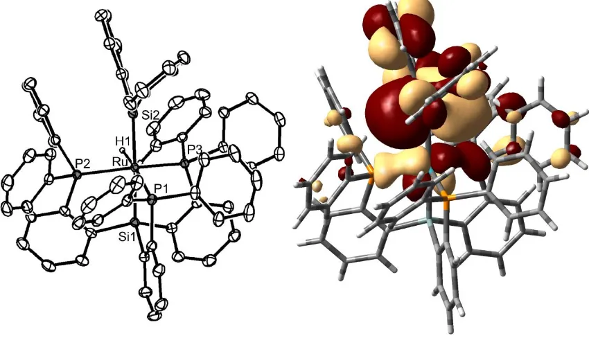
Figure 2.3. Left: Solid-state structure of 2.10a. Right: LUMO of 2.10a. Thermal
ellipsoids are set at 50% probability, and hydrogens on the phenyl rings and
solvent molecules have been removed for clarity. Selected bond lengths (Å) and
angles (°): Ru−Si(2), 2.2842(5); Ru−P(1), 2.3698(5); Ru−P(2), 2.2920(5);
Ru−P(3), 2.3130(5); Si(1) −Ru−Si(2), 175.58(2).
The solid-state structure, shown in Figure 2.3, corroborates this assignment and
reveals a terminal silylene ligand trans disposed to the silyl anchor of the [SiPPh3] −
ligand,
providing a Si1-Ru-Si2 angle of 175.58(2)°. As for the case of the phosphide complex 2.5,
[image:49.612.114.539.167.411.2]hydride ligand can be located in the difference map and resides at a position that is nearly
coplanar with the plane defined by the silylene moiety, providing evidence against direct
Si−H interactions. The Ru−Si bond length between the metal and the silylene moiety is
2.2842(5) Å and is slightly longer than other base-free ruthenium silylene complexes,21 manifesting the trans influence of the silyl donor. The addition of methylphenylsilane to
2.3 similarly results in the facile conversion to the silylene complex
[SiPPh3]Ru(H)(SiMePh) (2.10b), featuring 29Si{1H} resonances at δ = 359 and 101 ppm
(2JSiP = 18 Hz). As in 2.10a, the hydride resonance at δ = −9.21 ppm in the 1H spectrum
shows no coupling with the phosphines. Both 2.10a and 2.10b exhibit a single resonance
in the 31P{1H} NMR spectrum at 22 °C despite being six coordinate, as in 29. We presume that complexes 2.10a and 2.10b result from α-hydrogen migration from a
five-coordinate silyl intermediate, [SiPPh3]Ru(SiHR2), by analogy with the proposed manner
by which several other silylenes derived from silanes are thought to be formed.22
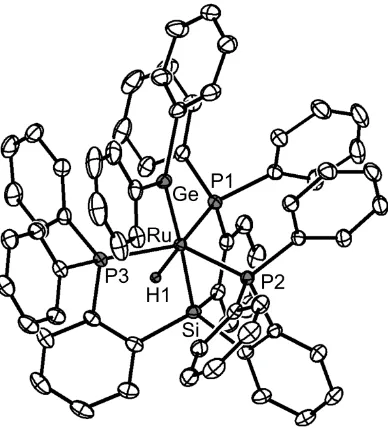
The germylene analogue of 2.10a is similarly obtained through the addition of
diphenylgermane to 2.3 (Scheme 2.4). Such a reaction cleanly affords
[SiPPh3]Ru(H)(GePh2) (2.11). As expected, complex 2.11 exhibits spectroscopic
characteristics closely resembling that of 2.10a, and an XRD study establishes that it is
nearly isostructural. The only significant difference arises from the Ru−Ge bond length of
2.3579(3) Å. This bond length is difficult to compare with other systems due to the dearth
of ruthenium germylene complexes, but is similar to the reported bond length of
2.339(1) Å in the related iridium complex, [PhB(CH2PPh2)3]Ir(H)2(GeMes2).23
Figure 2.4. Solid-state structure of 2.11. Thermal ellipsoids are set at 50%
probability, and hydrogen atoms on phenyl rings and solvent molecules are
removed for clarity. Selected bond lengths (Å) and angles (°): Ru−Ge, 2.3579(3);
Ru−P(1), 2.3709(5); Ru−P(2), 2.2955(5); Ru−P(3), 2.3136(5); Si−Ru−Ge,
[image:51.612.228.422.322.539.2]While bona fide examples of terminal silylene complexes have gained increasing
prominence in the literature,24 those that feature a strongly donating ligand trans to the silylene moiety are quite rare25 and may be expected to be unstable. Typical examples of complexes featuring a strong donor trans to a silylene ligand possess two
heteroatom-stabilized cyclic silylenes opposite one another.26 Accordingly, solutions of 2.10a and 2.10b decompose slowly to unknown products at room temperature over a few days but
are stable in the solid state at −35 °C. For comparison, the related six-coordinate iridium
silylene complexes [PhBPPh3]Ir(H)2(SiR2) (R = Mes, Ph, Et, Me)22,23 are prepared at
elevated temperatures and are appreciably more stable ([PhBPPh3]=[PhB(CH2PPh2)3] −
).
The addition of excess H2 gas to 2.10a affords two products, with the silane adduct
2.9 being the major species present. The minor product is obtained quantitatively via an
independent route through the addition of excess H2 gas to 2.3 and is assigned as the
dihydrogen hydride complex [SiPPh3]Ru(H)(H2) (2.12). Complex 2.12 features a broad
upfield resonance at δ = −4.3 ppm that exhibits coalescence even at −80 °C, making a
specific structural assignment difficult. However, the short T1min value of 33 ms recorded
at 0 °C (500 MHz 1H NMR) is consistent with a dihydrogen/hydride formulation.27,28 The dihydrogen ligand is labile, and 2.12 can hence be converted to 2.8 upon prolonged
exposure to dinitrogen. The formation of 2.12 likely results from silane displacement by
dihydrogen, as exposure of excess H2 gas to 2.9 results in partial conversion of 2.9 to
2.12 with loss of free silane. Addition of approximately 1 equiv of H2 gas to 2.10a further
results in formation of 2.9 with very little concomitant generation of 2.12.
The addition of methyllithium to 2.10a at −78 °C was examined to try to generate a
![Figure 1.2. Example model complexes of the generic formula [SiPiPr3]Fe(NxHy).](https://thumb-us.123doks.com/thumbv2/123dok_us/16391.1203/33.612.131.515.314.558/figure-example-model-complexes-generic-formula-sipipr-nxhy.webp)


![Figure 4.1. Solid-state structures of {[SiPiPr3]M(PMe3)}{BArF4} (M = Co (4.1,](https://thumb-us.123doks.com/thumbv2/123dok_us/16391.1203/107.612.122.530.236.595/figure-solid-state-structures-sipipr-m-pme-barf.webp)


