1 INTRODUCTION 1.1 General
Hardwood timber has been the preferred material for railway sleepers, and the maintenance work on exist-ing timber sleeper tracks continued to be provided by hardwood. Within Australia, the state of Queensland alone has over 8 million timber sleepers in service (Miller 2007). Most of these railway sleepers are de-teriorating and becoming less capable of meeting performance requirements. In order to maintain the track quality to a specified service level and ensure a safe track operation, damaged and deteriorated slee-pers are being replaced with new ones.
Yun & Ferreira (2003) reported that the Australi-an railway industry spends approximately 25-35 per-cent of its annual budget on rail track maintenance. According to Hagaman & McAlpine (1991), sleeper replacement represents the most significant mainten-ance cost for the railways, exclusive of the rail cost. Thus, several railway industries have adopted the spot replacement strategy to lessen the cost of track maintenance. The spot replacement strategy embrac-es the component replacement of failing timber slee-pers with new sleeslee-pers to maintain the railway tracks. A prerequisite of this maintenance strategy is that replacement sleepers should have properties compatible with that of existing timber sleepers.
Hardwood timber continues to be the most widely used sleeper material in a railway turnout (Za-rembski 1993). Turnout is a part of the railway where track crosses one another at an angle to divert
a train from the original track. The special sleepers laid on a turnout are called turnout sleepers. These sleepers have varying lengths and fastening locations (AS1085.14 2003). In a railway turnout, the sleepers are subjected to a combined flexural and shear loads due to the force caused by a crossing train. Because of the special nature of turnout sleepers, its manufac-turing procedure is different from that of mainline sleepers which makes its maintenance more costly. A footprint of every single sleeper to be replaced needs to be pre-measured on the site and then fabri-cated at the factory with accurate bolt holes. Thus, an alternative material with similar usability and de-sign characteristics to that of hardwood sleepers is more suitable.
1.2 Spot replacement of timber sleeper
The interest in replacing timber sleepers in the exist-ing railway track with other materials has been sti-mulated by the increased scarcity of quality timber (Van Erp et al. 2005). Currently, several railway in-frastructure industries are replacing only the deteri-orated sleepers in the railway track (spot replace-ment) to reduce the cost of maintenance. This maintenance practice leads to a situation where in the existing timber sleeper track; the replacement sleeper will be of different material and possibly dif-ferent performance characteristics in service. In a study conducted by Birks et al. (1989), they found out that when steel sleepers are used to replace a de-teriorated timber sleeper, the steel sleepers was
tak-Analysis of a railway turnout system with a spot replacement sleeper
A.C. Manalo, T. Aravinthan & W. Karunasena
Faculty of Engineering and Surveying, University of Southern Queensland, Toowoomba, Australia
ing a much reduced load compared with the adjacent timber sleepers. Higher deflections were also record-ed for the steel sleeper showing a lower support be-ing supplied to the railway track at the steel sleeper installations. They suggested however, that similar rail seat loads and deflections can be achieved by steel sleeper to the adjacent timber sleepers through careful installation procedures and by properly packed ballast. In another study, Kohoutek (1991) found a variation between the performance of con-crete and timber sleepers. He concluded that this var-iation is caused by the different materials of sleepers mixed in the track. Similarly, the differing height of the timber sleeper to that of the concrete resulted in the load not spread evenly among the sleepers. When a fibre composite railway sleeper is used as a re-placement sleeper, it is important that this sleeper closely matches the dimensions and the overall stiff-ness of the existing timber sleepers to minimize the uneven distribution of forces.
In this paper, an investigation on the behavior of a railway turnout system when the most critical slee-per is replaced with a low MOE is investigated. This is conducted to simulate the spot replacement main-tenance strategy and to determine the maximum bending, shear and deflection in the turnout sleepers. Similarly, a comparison of the effectiveness of a fi-bre composites material between a steel and concrete for spot replacement sleeper was conducted.
2 FE MODEL FOR RAILWAY TURNOUT 2.1 Simplified grillage beam analogy
A railway turnout consists of a number of sleepers and rails acting together. In most studies reported on the behavior of sleepers in a railway track, the finite element analyses are implemented using only a sin-gle sleeper (Kohoutek 1991, Shokreih & Rahmat 2007, Ticoalu 2008). However, the presence of at least two sets of continuous rails which connects the sleepers makes the inclusion of the entire turnout es-sential in the analysis. For this reason, the behavior of turnout sleepers should be determined for a group of sleepers instead of a single sleeper, as the contri-bution of the neighboring sleepers should be taken into account due to the joining effects of the rails.
The AS 1085.14 (2003) suggests that the turnout sleepers can be analyzed by a more complex grillage model. However, there has been no reported study on the use of such a model to analyze a railway tur-nout in literature. The commonly available literature on grillage system is in the analysis of slabs, founda-tions and complex structures (Tan et al. 1998, Fuji-kubo 2005). These studies showed that the grillage beam system has been used to analyze complex structures because of its simplicity but still providing reasonable results. A similar model was developed in this study using Strand7 finite element software
package (Strand7, 2005) to investigate the effect of various parameters on the behavior of railway tur-nout sleepers.
2.2 Railway turnout geometry
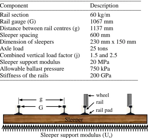
[image:2.595.308.551.327.553.2]A standard 1 in 16 right-hand turnout geometry us-ing 60 kg/m rail and a narrow gauge (1067 mm) rail line commonly used in Queensland, Australia is ana-lyzed. Sleeper dimensions were set at 230 mm x 150 mm in consideration of the replacement of deteri-orating turnout timber sleepers. A combined vertical design load factor, j (including quasi-static and dy-namic) as large as 2.5 is used as recommended by AS1085.14 (2003). The maximum contact pressure at the sleeper-ballast interface for high-quality, abra-sion resistant ballast of 750 kPa based from Austral-ian Standards AS2758.7 (1996) was adopted. Table 1 details the components of the track structure and Figure 1 shows the schematic diagram for a turnout sleeper.
Table 1. Details of the components of the track structure. ______________________________________________ Component Description ______________________________________________ Rail section 60 kg/m
Rail gauge (G) 1067 mm Distance between rail centres (g) 1137 mm Sleeper spacing 600 mm
Dimension of sleepers 230 mm x 150 mm Axle load 25 tons
Combined vertical load factor (j) 1.5 and 2.5 Sleeper support modulus 20 MPa Allowable ballast pressure 750 kPa Stiffness of the rails 200 GPa
[image:2.595.309.543.332.531.2]_____________________________________________
Figure 1. Schematic diagram of a railway turnout sleeper.
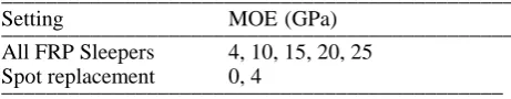
In the numerical simulation, the effect in the beha-vior of turnout timber sleepers when the most critical sleeper is replaced with a lower MOE is investi-gated. Only the load case where the wheel load pro-duces the highest positive bending moment, shear and deflection in the turnout sleepers was consi-dered. In the previous analysis by the authors (Mana-lo et al. 2010), the highest maximum bending mo-ment and shear forces are produced between the switch and the frog. This corresponds to sleeper 68 and 42, respectively. In the spot replacement analy-sis, four higher MOE values for existing timber tur-nout sleepers in the Australian railway lines with the subgrade modulus kept constant at 20 MPa were in-vestigated. A summary of the design parameters is listed in Table 2. In the table, the All FRP sleepers
g G
Sleeper support modulus (Us)
rail wheel
Sleeper
represents the FE model where all the sleepers in the railway turnout system have the same MOE while the spot replacement represents the simulation where only the most critical sleeper in the railway turnout system is replaced with a low MOE.
Table 2. MOE of sleepers in a railway turnout system. ______________________________________________ Setting MOE (GPa)
______________________________________________ All FRP Sleepers 4, 10, 15, 20, 25
Spot replacement 0, 4
_____________________________________________
2.3 Finite element model of the railway turnout
A simplified three dimensional grillage model con-sisting of longitudinal and transverse beam elements has been developed to analyze the behavior of rail-way turnout structure. The model consists of the rails, sleeper plates, sleepers, ballast, and subgrade. The finite element (FE) model considers the rails as long beams continuously supported by equally spaced sleepers. The model consists of a total of 107 sleepers including 10 transition sleepers before the switch and after the longest sleeper in the turnout as shown in Figure 2. The transition sleepers are pro-vided to ensure that the wheel load is sufficiently distributed over several sleepers when the train en-ters and leaves the turnout. Sadeghi (2001) sug-gested that the effects of wheel loads are negligible for sleepers located more than 5 m or 10 sleepers away from the load points, i.e. sleeper number 1 has almost zero bending moment, shear and deflection when the wheel load is directly over sleeper number 11. The sleepers are laid perpendicular to the through tracks with increasing lengths from the switch until two standard length sleepers can be placed under the through and divergent tracks. The overall length of the modeled track is 61.8 m with sleeper lengths varying from 2.30 m to 4.1 m and the sleeper ends having lengths of 0.58 m.
The rails and the sleepers are modeled as a gril-lage beam system with the sleepers resting on an elastic foundation. The effect of irregularities on the track and wheels and the dynamic effects are as-sumed to be represented by the dynamic load factor. A total of 1339 Beam2 elements and 1046 nodes were used in the turnout model. As the exact cross-section of the 60 kg/m rail (AS 1085.1 2002) cannot be defined in Strand7 using only 2D beam element, an approximate steel I-section with an almost equiv-alent moment and torsional inertia was used for the rail. The sleepers were considered as isotropic beams with a homogenous cross section.
The beam elements were used to connect the rail and the sleepers, which were placed at the level of their respective centroids. These beam elements representing the rail pads are modeled with an axial stiffness of 310 x 106 N/mm in compression which is equivalent to that of the 19 mm thick double shoulder level base rolled-steel sleeper plate used for 146 mm rail base (AS1085.3, 2002) and a tension stiffness of 130 x 103 N/mm which is equivalent to the static vertical stiffness of timber screw spikes. Only the equivalent static wheel load acting on the vertical direction is considered with no lateral and longitudinal loads. The 3 sets of wheel load shown in Figure 3 were applied directly to the rails. In this figure, R1 represents the rail seat load at the middle
wheel set while R2 corresponds to the front and the
rear wheel sets. In the calculation of rail seat load, a combined vertical design load factor of 2.5 is applied to rail seat load, R1 while a vertical load factor of 1.5
is applied in the front and the rear seat loads, R2.
[image:3.595.32.263.120.165.2]This loading pattern simulates an axle load of 25 tones for a typical heavy axle load common in most Australian railway lines. These 3 sets of wheel load are moved though the turnout tracks to determine the location of the most critical sleepers.
Figure 2. Geometry of a 1:16 standard right-hand railway turnout system.
0 5 10 15 20 25
32 33 34 35 36 37 38 39 40 41 42 43 44 45 46 47 48 49 50 51 52
B
M
(
k
N
-m)
Sleeper number
BM along turnout sleepers
All_4 All_10 All_15 All_20 All_25
0_10 4_10 4_15 4_20 4_25
3 RESULTS AND DISCUSSION
The behaviour of the turnout sleepers when one of the sleepers in a railway turnout is replaced with a low MOE is presented here. In the numerical simula-tion of the spot replacement sleepers, the most criti-cal sleepers, sleepers 42 and 68 were assigned with a low MOE while keeping the elastic modulus of the other sleepers the same to determine the maximum bending, shear and deflection in the railway turnout sleepers. In the analysis of results, the 10 sleepers before and after sleepers 42 and 68 were included. 3.1 Bending moments in sleepers
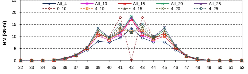
The distribution of maximum bending moment among the sleepers in the railway turnout system is shown in Figure 4. In this figure, All_4, All_10, All_15, All_20, and All_25 represent the railway track supported by turnout sleepers with the same value of MOE. On the other hand, the railway track when the most critical sleeper is replaced by a fibre composite sleeper with an MOE = 4 GPa is desig-nated as 4_10, 4_15, 4_20, and 4_25. The railway turnout supported by MOE = 10 GPa with the most critical sleeper replaced by a very flexible or a dam-aged sleeper (elastic modulus of only 1 MPa) is in-cluded for comparison and is designated as 0_10.
As can be seen from the figure, the behavior of turnout sleepers with the same MOE is almost the same. This is similar to results of the investigation by Ticoalu (2008) wherein she found no significant difference in the maximum bending moment, shear and vertical deflection for turnout sleepers with MOE of 10 GPa or higher and are resting on a sub-grade of 20 to 40 MPa. However, it can be seen from the figure that replacing sleepers 42 with an MOE = 4 GPa has a large influence on the behaviour of the group of turnout sleepers. The results show that the sleeper directly under the rail seat load R1 has the
highest bending moment. In a railway turnout sup-ported by sleepers with the same MOE (All_10, All_15, All_20 and All_25), the magnitude of bend-ing moment in sleeper 42 is around 18 kN-m while in its adjacent sleepers is around 12 kN-m. Similarly, the magnitude of the bending moment in sleeper 42 for railway turnout with MOE of 10 to 25 GPa is
on-ly 20% higher to the bending moment experienced in All_4.
Replacing sleeper 42 with an MOE = 4 GPa leads to a lowering overall stiffness of the railway track and therefore a reduction in the bending moment starts to occur in the sleeper just below the load. A reduction in the magnitude of bending moment of almost 30% was observed for sleeper 42 compared to a railway turnout not mixed with a lower MOE even though R1 is directly over this particular
slee-per. This reduction in the bending moment in sleeper 42 is however distributed to the neighbouring slee-pers as seen by the increase in the bending moment of sleepers 41 and 43. For all the investigated MOE value, there is no significant difference in the bend-ing moment in the spot replacement sleeper but the increase in the bending moment in the adjacent slee-pers can go as high as 20% for higher MOE. On the average, the bending moment in the adjacent slee-pers is 22% higher than that of sleeper 42. This re-sult shows that a fibre composites sleeper is more ef-fective than steel for a spot replacement sleeper. Birks et al. (1989) indicated that a steel sleeper si-tuated immediately below the load source carries an almost 38% lower bending moment compared to the adjacent timber railway sleepers.
[image:4.595.40.551.628.781.2]The increase in the bending moment in the adja-cent sleepers in 4_10, 4_15, 4_20, and 4_25 is sig-nificantly less compared to that of the adjacent slee-pers when the spot replacement sleeper has a very low elastic modulus value (MOE = 1 MPa). Similar-ly, the increase in the bending moment in the adja-cent sleepers in 0_10 compared to the railway tur-nout not mixed with a low stiffness sleeper is around 45%. This is almost similar to the observations by Zhang et al. (2008) when they examined the re-sponse of a railway track with unsupported sleepers. In their numerical investigation, they represented the unsupported sleeper with a zero value for MOE. Their results showed that the calculated bending moment in the neighboring sleepers when the train passes over an unsupported sleeper is almost 40% higher compared with under normal condition. Fur-thermore, the maximum bending moment in the sleepers 41 and 43 for 0_10 is slightly higher than
0 40 80 120 160 200
58 59 60 61 62 63 64 65 66 67 68 69 70 71 72 73 74 75 76 77 78
V
(
k
N
)
Sleeper number V along turnout sleepers
All_4 All_10 All_15 All_20 All_25
0_10 4_10 4_15 4_20 4_25
-10 -8 -6 -4 -2 0
58 59 60 61 62 63 64 65 66 67 68 69 70 71 72 73 74 75 76 77 78
D
e
fl
e
c
ti
o
n
(
m
m
)
Sleeper number
Deflection along turnout sleepers
All_4 All_10 All_15 All_20 All_25
0_10 4_10 4_15 4_20 4_25
that of sleeper 42 in a normal railway track. This should not be the case especially when the sleeper is designed based on the maximum bending moment acting on the sleepers for a track with a constant MOE. This increased bending moment taken by the adjacent sleepers might result in its early in-service failure. Interestingly, the bending moment expe-rience by the spot replacement sleeper is almost sim-ilar to the bending moment in All_4 suggesting a better distribution of load among the sleepers. Thus, it can be said that the fibre composite sleepers can be used not only for spot replacement but also in the to-tal replacement of sleepers in a railway turnout. 3.2 Shear forces on sleepers
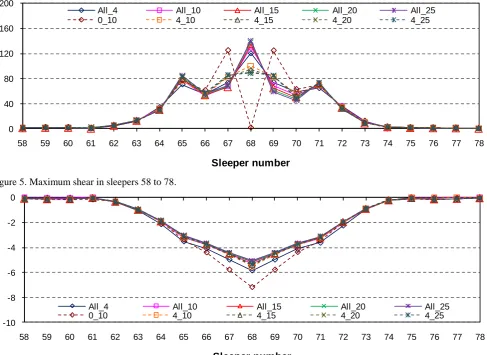
Figure 5 shows that the shear force in sleeper 68 is at its highest value when R1 is directly over this
slee-per. For a railway turnout without a spot replacement sleeper, the magnitude of shear force in sleeper 68 is at 140 kN, which is almost 50% higher than that of the shear force in the adjacent sleepers. Considering the load is directly over sleeper 68, the shear force at the sleepers 67 and 69 are almost same. When slee-per 68 is replaced with an MOE = 4 GPa, the shear force in sleeper 68 decreases to 95 kN while in the adjacent sleepers increases to 85 kN. This represents an over 30% decrease in shear force in the spot re-placement sleeper but only a 20% increase in shear
force in the adjacent sleepers with the shear force among sleepers 67 to 69 differ by only 10%. A slight increase in shear force was also observed in the neighboring sleepers. In the evaluation of Kohoutek (1991) between the performance of a railway track with mixed timber and concrete sleepers, he found out that the distribution is 30% to timber and 35% to the adjacent concrete sleepers when the load is over the timber sleeper but over 60% for concrete sleeper when the load is directly over the concrete sleeper. This result again showed that a fibre composite slee-per distributes the load better to the adjacent sleeslee-pers than a concrete sleeper.
3.3 Vertical deflection of sleepers
[image:5.595.56.544.45.400.2]The maximum vertical deflection in turnout sleeper occurred under the rail seat. In Figure 6, the results show that replacing sleeper 68 with an MOE = 4 GPa did not significantly change the maximum def-lection in the turnout sleepers compared to that of a railway turnout with all the sleepers having the same elastic modulus. The magnitude of vertical deflec-tion in sleeper 68 is well under 6 mm for all the con-sidered MOE. On the other hand, replacing sleeper 68 with a very low elastic modulus (MOE = 1 MPa) would result to an almost 35% increase in the deflec-tion of the adjacent sleepers. This is almost similar to the results obtained by Lundqvist and Dahlberg
Figure 5. Maximum shear in sleepers 58 to 78.
(2005) wherein they found out that the vertical dis-placement of sleepers adjacent to an unsupported sleeper increase by 40%. In the earlier studies by Birks et al. (1989), they have observed a deflection of 9 mm for the inserted steel sleeper compared to only 5 mm for timber when not mixed with a steel sleeper. These results show that a sleeper material with stiffness characteristics similar to that of timber is a more effective spot replacement sleeper for tim-ber sleepers in a railway turnout system than con-crete and steel.
The sleeper deflection under the rail is the main criterion in a railway track analysis (Zakeri & Sa-deghi, 2007). For railway tracks in Australia, the maximum static deflection in a railway structure on ballasted track should be around 6.35 mm to give re-quisite combination for flexibility and stiffness (Jeffs & Tew, 1991). The results indicated that an MOE = 4 GPa is needed for a spot replacement sleeper for the timber sleeper railway turnout track to not ex-ceed the maximum allowable vertical deflection provided that the subgrade modulus is at least 20 MPa or a subgrade of at least good subsoil (gravel). This MOE value for sleeper also satisfies the rec-ommended maximum allowable contact pressure be-tween the sleeper and the ballast of 750 kPa.
4 CONCLUSIONS
A grillage beam model was used to investigate the behaviour of a railway turnout system with a spot replacement sleeper. Based on the results of the FE simulation, the following conclusions can be drawn:
The grillage beam analogy is reasonable to model a railway turnout system as they are producing results comparable to that of other researchers.
A spot replacement sleeper with a lower MOE leads to a lowering overall stiffness of the rail-way track.
The bending moment and shear in the spot re-placement sleeper are 30% lower than sleepers in the railway track with same MOE.
A spot replacement sleeper with an MOE of 4 GPa and support modulus of 20 MPa satisfies the requirement for maximum allowable vertical deflection of 6.35 mm.
A fibre composites spot replacement sleeper is more effective than steel and concrete sleepers in distributing load to the adjacent sleepers.
5 ACKNOWLEDGEMENTS
The technical assistance of Mr. Steve Douglas and Dr. Nick Stevens in the design and analysis of fibre composite turnout railway sleepers is gratefully ac-knowledged.
6 REFERENCES
Birks, F.J., Tew, G.P., & Chitty, G.B. 1989. Narrow gauge track with interspersed steel sleepers. The Fourth Interna-tional Heavy Haul Railway Conference, Brisbane, 297-302. Fujikubo, M. 2005. Structural analysis for the design of VLFS.
Marine Structures 18: 201-226.
Hagaman, B.R. & McAlphine, R.J. 1991. ROA timber sleeper development project. Proc. Eight International Rail Track Conference, Rail Track Association of Australia, 233-237. Jeffs, T. & Tew, G.P. 1991. A review of track design
proce-dures: Volume 2 – Sleepers and ballast, Railways of Aus-tralia, Melbourne, Australia.
Kohoutek, R. 1991. Dynamic and static performance of inters-persed railway track. Railway Engineering Conference, Adelaide, Australia.
Kohoutek, R. & Campbell, K.D. 1989. Analysis of spot re-placement sleepers. The Fourth International Heavy Haul Railway Conference, Brisbane, 316-321.
Lundqvist, A. & Dahlderg, T. 2005. Load impact on railway track due to unsupported sleepers. Journal of Rail and Rap-id Transit 219: 67-77.
Manalo, A.C., Aravinthan, T., Karunasena, W., & Stevens, N. 2010. The effect of modulus of elasticity on the behavior of railway turnout sleepers. Proc. 21st Australasian Conf. on the Mechanics of Structures and Materials (ACMSM21),
Victoria University, Melbourne, Australia. pp. 427-432. Miller, R. 2007. Rail and tramway sleepers: Product
recogni-tion, identification and presentarecogni-tion, viewed 29 May 2008,
www.cqfa.com.au/documents/1181619278_sleepers_fact_s heet.pdf
Sadeghi, J. 2001. Investigation on modeling of railway track system. Scientia Iranica 8(1): 76-79.
Shokrieh, M.M. & Rahmat, M. 2007. Effects of Young’s mod-ulus on response of railway sleeper. Applied Mathematical Modelling 31: 700-711.
AS1085.1-2002. Railway track material, Part 1: Steel rails. Standards Australia, Sydney.
AS 1085.3-2002. Railway track material, Part 3: Sleeper plates. Standards Australia, Sydney.
AS1085.14-2003. Railway track material, Part 14: Prestressed concrete sleepers. Standards Australia, Sydney.
AS2758.7-1996. Aggregates and rock for engineering purposes, Part 7: Railway ballast. Standards Australia, Sydney. Strand7 (2005). Strand7 Release 2.3.7 finite element analysis
system, Sydney, Australia.
Tan, G.H., Brameld, G.H. & Thambiratnam, D.P. 1998. Devel-opment of an analytical model for treating bridge-vehicle interaction. Engineering Structures 20(1-2): 54-61.
Ticoalu, A.N.E. 2008. Investigation on fibre composite turnout sleepers, Master of Engineering dissertation, University of Southern Queensland, Toowoomba, Queensland, Australia. Van Erp, G., Cattell, C., & Heldt, T. 2005. Fibre composite
structures in Australia’s civil engineering market: an anato-my of innovation. Progress in Structural Engineering Ma-terials 7: 150-160.
Yun,W.Y. & Ferreira, L. 2003. Prediction of the demand of the railway sleepers: A simulation model for the replacement strategies. International Journal of Production Economics
81-82: 589-595.
Zakeri, J. & Sadeghi, J. 2007. Field investigation on load dis-tribution and deflections of railway track sleepers. Journal of Mechanical Science and Technology 21: 1984-1996. Zarembski, A.M. 1993. Concrete vs. wood ties: Making the
economic choice. Conf. Maintaining Railway Track: De-termining Cost and Allocating Resources, Arlington, VA. Zhang, S., Xiao, X., Wen, Z., & Jin, X. 2008. Effect of