i
PIEZOELECTRIC STORING CIRCUIT DESIGN
NOREZMI BINTI MD JAMAL
This Report Is Submitted in Partial Fulfilment of Requirements for the Bachelor Degree of Electronic Engineering (Industrial Electronic)
Fakulti Kejuruteraan Elektronik dan Kejuruteraan Komputer Universiti Teknikal Malaysia Melaka
ii
REPORT STATUS VERIFICATION FORM
UNIVERSTI TEKNIKAL MALAYSIA MELAKA
FAKULTI KEJURUTERAAN ELEKTRONIK DAN KEJURUTERAAN KOMPUTER
BORANG PENGESAHAN STATUS LAPORAN PROJEK SARJANA MUDA II
Tajuk Projek : PIEZOELECTRIC STORING CIRCUIT DESIGN Sesi
Pengajian
: 1 2 / 1 3
Saya NOREZMI BINTI MD JAMAL mengaku membenarkan Laporan Projek Sarjana Muda ini disimpan di Perpustakaan dengan syarat-syarat kegunaan seperti berikut:
1. Laporan adalah hakmilik Universiti Teknikal Malaysia Melaka.
2. Perpustakaan dibenarkan membuat salinan untuk tujuan pengajian sahaja.
3. Perpustakaan dibenarkan membuat salinan laporan ini sebagai bahan pertukaran antara institusi pengajian tinggi.
4. Sila tandakan ( √ ) :
SULIT*
*(Mengandungi maklumat yang berdarjah keselamatan atau
kepentingan Malaysia seperti yang termaktub di dalam AKTA
RAHSIA RASMI 1972)
TERHAD**
**(Mengandungi maklumat terhad yang telah ditentukan oleh
organisasi/badan di mana penyelidikan dijalankan)
iii
STUDENT’S DECLARATION
“I hereby declare that this report is the result of my own work except for quotes as cited in the references”
Signature: ……….
Author: NOREZMI BINTI MD JAMAL
iv
SUPERVISOR’S DECLARATION
“I hereby declare that I have read this report and in my opinion this report is sufficient in terms scope and quality for the award of Bachelor of Electronic Engineering
(Industrial Electronic) With Honours”
Signature: ……….
Name: Dr Kok Swee Leong
v
ACKNOWLEDGEMENT
vi
ABSTRACT
vii
ABSTRAK
viii
TABLE OF CONTENTS
PIEZOELECTRIC STORING CIRCUIT DESIGN i
REPORT STATUS VERIFICATION FORM ii
STUDENT’S DECLARATION iii
SUPERVISOR’S DECLARATION iv
ACKNOWLEDGEMENT v
ABSTRACT vi
ABSTRAK vii
TABLE OF CONTENTS viii
LIST OF FIGURES xi
LIST OF TABLES xiii
CHAPTER 1 1
INTRODUCTION 1
ix
1.2 Problem Statement 3
1.3 Objectives 4
1.4 Scope of Project 5
1.5 Report Outline 5
CHAPTER 2 6
LITERATURE REVIEW 6
2.1 Background 6
2.2 Energy Harvesting 7
2.3 Vibration-Based Energy Harvesting 11
2.4 Piezoelectric As Energy Harvester 14
2.5 Energy Storage element 18
CHAPTER 3 21
PROJECT METHODOLOGY 21
3.1Flow Chart of Project 21
3.2Circuit Design and Simulation 22
3.2.1 Circuit Design Theory 22
3.2.2 Circuit Simulation 30
3.2.3 Experimental Setup 33
3.3 PCB Fabrication Process 37
x
ANALYSIS AND DISCUSSION 38
4.1 Introduction 38
4.2 Theoretical and Simulation Result 38
4.3 Experimental Result 49
4.4 Conclusion 58
CHAPTER 5 59
CONCLUSION AND RECOMMENDATION 59
5.1 Conclusion 59
5.2 Recommendation 60
REFERENCES 62
xi
LIST OF FIGURES
Figure 1: Wireless Sensor Node with Energy Harvesting System [16] 9
Figure 2: Vibration power spectra [21] 12
Figure 3: William and Yates Linear Mass- Spring Damper System [4, 22] 12 Figure 4 Electromechanical conversion via piezoelectricity phenomenon [13]. 15 Figure 5 : Types of piezoelectric energy harvesters (a) d31 mode (b) d33 mode [20] 16
Figure 6: Power density versus lifetime for batteries and ambient sources [29] 20 Figure 7: Flow chart of Piezoelectric Storing Circuit Design 21 Figure 8: Block diagram of piezoelectric storing circuit design 23
Figure 9: Bridge Rectifier Circuit 23
Figure 10: Ripple Voltage in Rectifier Voltage 24
Figure 11: Voltage and Power Capacitor with Varying Time 27
Figure 12: Simple Zener Voltage Regulator 28
Figure 13: Multivibrator Circuit 29
Figure 14: Rectifier Circuit Using Multisim 31
Figure 15 Rectifier Circuit Using LTspice 31
Figure 16: Simple Voltage Regulation using Multisim 32
Figure 17: Simple voltage regulation using LTspice 32
Figure 18: Alternate Blinking Circuit Simulation using Multisim 32
Figure 20: Experimental Set-Up 33
Figure 19: Alternate Blinking Circuit Simulation Using LTspice 33
Figure 21: Piezoelectric Transducer 35
Figure 22: IC Bridge Rectifier W005G 35
Figure 23: Super-capacitor as Storage Element 36
xii
Figure 25: Circuit Design using Proteus Software 37
Figure 26: Output Rectifier Waveform using Multisim 39
Figure 27: Output Rectifier Waveform using LTspice 39
Figure 28: Regulated Voltage 4.7V 44
Figure 29: Voltage Capacitor varied with Time 45
Figure 30: First Stage of DC analysis 47
Figure 31: Second Stage of DC Analysis 48
Figure 32: Voltage Generated From Piezoelectric Device 50
Figure 33: Output Voltage Response with Varying Frequency 51 Figure 34: Peak to Peak Input Voltage from Piezoelectric 52 Figure 35: Rectifier Output Voltage without Capacitor Filter 53 Figure 36: Charging and discharging time of varying capacitor 54 Figure 37: Extrapolation of charging and discharging time with varying capacitor 55 Figure 38: Alternate Blinking Using Piezoelectric Source 56
Figure 39: LTC3588 Piezoelectric Energy Harvester 60
xiii
LIST OF TABLES
Table 1 Extrapolated data for estimating the full charging duration of 1mA h 9
Table 2 Characteristics of Typical Energy Harvester 11
Table 3: Characteristics of typical energy storage options 19
Table 4: Rectifier Circuit using 4 diodes 31
Table 5: Simple Voltage Regulation 32
Table 6: Output Rectifier Voltage 40
Table 7: Average Value of Rectifier Voltage 41
Table 8: RMS Value of Rectifier Voltage 42
Table 9: Ripple Factor for Both Simulations 42
Table 10: Regulated Voltage with Varying Input Voltage 43
Table 11: Energy Stored in Capacitor 46
Table 12: Alternate LED Blinking in Simulation 46
Table 13: Current Triggering the BJT Transistor 49
Table 14: The Measured Value of Rectifier Voltage 53
Table 15: Measured and Theoretical Ripple Factor 54
Table 16: Current Flow Trigger Transistor 57
1
CHAPTER 1
INTRODUCTION
1.1 Overview
2
essentially a transducer device which can perform energy conversion from kinetic or mechanical energy into electrical energy
Since energy harvesting is popular among many researchers, the various inventions and applications that related to energy harvesting are created to apply the theoretical. For example, the handheld electronic devices using solar panel or piezoelectric devices, remote wireless sensors using solar panel or RF energy from antenna, remote wireless actuators using thermal energy and others have been created for low cost and more convenient. Energy harvesting sources are usually used to power up electronic applications or devices, which is used in very small amount of power or low-energy needed. Thus, the applications for nowadays have been changed to a more sustainable, resource efficient and low carbon economy. This is because, to protect the earth and to ensure that industrial, climate, energy, environmental and other relevant policies provide consistency, coherence and certainty and create the right conditions for innovation [2].
Then, piezoelectric storing circuit design is proposed as a final year project in order to decrease the cost and for long lasting operability as well as to show the harvested energy can be stored and then will be used such battery-less and event trigger application. Piezoelectric is a transducer that converts mechanical energy to usable electrical energy especially for vibration, which is one of the energy harvesting sources. Any environmental vibrations energy is mechanical energy which is suitable to convert it into electrical energy using piezoelectric for reuse the lost energy that normally occur around most machines and biological systems. The instance of piezoelectric storing circuit design can be applied in the event trigger application or battery charger. A battery charger is a device used to put energy into a cell or rechargeable battery by forcing an electric current through it. Lead-acid battery chargers typically have two tasks to accomplish. The first is to restore capacity, often as quickly as practical. The second is to maintain capacity by compensating for self discharge. In both instances optimum operation requires accurate sensing of battery voltage [3].
3
voltage source, compact of configuration, compatible with micro electromechanical system (MEMS) and high coupling in single crystals with less energy losses. Then, electrical energy that produces from piezoelectric is usually an alternative current mode with an instantaneous peak voltage which is proportional to the level of vibration. In order to create piezoelectric storing circuit design, rectifier is needed for converting the AC power into DC power and other required components in circuit are also needed to fulfil the requirement for harvested energy applications. Therefore, for long lasting operability, super capacitor or rechargeable battery are required to work together with the piezoelectric device as an energy storage element, which is then used to power up the small electronic systems with low power consumption to be operated automatically.
1.2 Problem Statement
Piezoelectric is a device that capable to generate a voltage when a corresponding mechanical stress is applied. The piezoelectric materials are usually fabricated in the form of a cantilever structure. Electrical energy is produced when the cantilever operates in bending mode at resonant frequency [4]. Hence, there are some problems while handling the energy harvesting and some external problem that need energy harvesting to be used, have been stated by following below:
a) The power that produced from piezoelectric is in an AC power which is unregulated and relatively low output voltage [5]. However, in order to use in circuit application such as for low power electronic components, DC power is required.
b) The average harvested power from piezoelectric is too small [6] due to the high internal impedance restricts the amount of output current that can be driven by the piezoelectric source to the micro-amp range [5].
4
components. Therefore the voltage generated from piezoelectric, which proportional to the mechanical stress, should be regulated before being used to power-up electronic devices [7].
d) On the other hand, the use of traditional battery in the low power electronic components is has a limited power or lifespan [8]and expose easily to the pollution due to the chemical use in the battery.
The above problems are addressed in this project by considering several aspects in order to start the piezoelectric storing circuit design. Hence, the first thing to do is by identifying the way to transform AC power to DC power. So, rectifier circuits that are suitable for power conversion with a piezoelectric source will be used [5]. Generally, a bridge rectifier is used as an ac-dc rectifier that has own advantages.
Next, some storage elements are used to store and accumulated the harvested energy for intermittent use since the average power is too little. The use of capacitors as a way to store energy has been considered due to the past research on the power energy harvesting [9] as well as can overcome the problem of traditional battery that as limited power. Then, the protection circuit will be used since inconsistent applied voltage. Therefore, the piezoelectric harvesting circuits for circuit application designs were studied.
1.3 Objectives
There are some objectives of this final year project that need to be achieved due to the following aspects below:
a) To design and analyze of piezoelectric energy harvesting storing circuit b) To construct and demonstrate the application of the piezoelectric storing
5
1.4 Scope of Project
Since there are many issues about piezoelectric as energy harvesting device, so, this project just focus on the following properties below:
a) This project emphasizes on the piezoelectric storing circuit design with maximum input frequency of 300Hz.
b) Piezoelectric material off-the shelf is used in this project and the size of piezoelectric device that is used is 0.51mm T x 31.8 mm W x 63.5 mm L.
c) Output voltage from piezoelectric device is produced up to 3V.
d) Low power electronic components in the range 10mW and 30mW produced from piezoelectric material will be applied to power up low power electronic applications.
1.5 Report Outline
6
CHAPTER 2
LITERATURE REVIEW
2.1 Background
The market sale of low power electronics and wireless technology increase gradually year by year. Nowadays, electronic technologies are being familiar with an embedded system that consist of software and hardware component as well as user friendly especially for intelligent building, home automation, autonomous vehicle and health monitoring. Hence, the embedded system also have been environmental friendly in order to provide green, clean and renewable electrical energy sources with ambient energy sources or wasted energies. Most of the low powered electronics devices rely on the batteries as a power sources to power up the devices. However, the powers of batteries are limited. In short, energy harvesting can overcome the issue of limited lifespan of batteries and the pollutions [10]. Thus, it will reduce the cost and avoid the chemical waste that might harm environment.
7
convert the ambient waste energy into the useful electrical energy. This is according to one of the researchers, to realize the need for power storage circuitry, who speculated the use of piezoelectric materials for harvesting numerous sources of energy around the body, including limb and finger motion [11]. Moreover, there are three basics vibration-to-electric energy conversion mechanism, which are the electromagnetic, electrostatic and piezoelectric transductions [12].
Hence, the piezoelectric transduction has received greatest attention in order to generate electricity from vibrations. Therefore, the vibration based energy can be used in powering up the electronic devices with small amount power. For example, according to the project of piezoelectric generator harvesting bike vibrations energy to portable devices, it has stated that energy harvest from vibration has produced low power with 3.5 mW to power LED-lamp of bicycle. The vibration that has been captured while riding the bicycle was at 5ms-2 and 12.5Hz. Moreover, power that has been transformed by using piezoelectric generator is sufficient to recharge a battery, or to power up the low consumption devices [13].
However, energy-harvesting system designs will address the power uncertainty; so, it will be overcome by incorporating an energy storage element of some kind in the power-management circuitry. In fact, energy storage is essential for dealing the ambient sources especially with piezoelectric converters in applications that do not have strictly periodic movement in converting the mechanical power to electrical power. Having energy storage as part of the important circuitry, therefore, direct application of the piezo-film as a power source is not practical. It is
unavoidable to use a storage device to collect the weak power output for future
usage.
2.2 Energy Harvesting
8
recent years. There are many applications of wireless sensor network that offer an attractive solution such as environmental monitoring, safety, security and military applications, animal tracking and control, built environment and health [14, 15]. So, with energy harvesting, it can enable once device or application be a self powered electronic components as well as can save the cost, low maintenance and reduce the chemical waste resulting from the use and replacement of conventional batteries. Hence, there are a number of general definitions of the term energy harvesting. According to Kompis and Sureka [16], energy harvesting is a means of powering wireless sensor nodes by converting many low grade ambient energy sources such as environmental vibrations, human power, thermal sources, solar power, wind energy and their conversion into useable electrical energy.
9
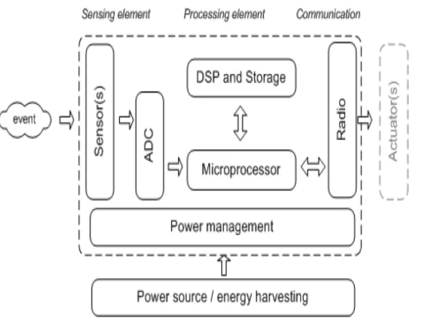
Figure 1: Wireless Sensor Node with Energy Harvesting System [16]
Besides, energy harvesting is the process by which energy readily available from the environment such as solar, vibration, heat, and others is captured and converted into usable electrical energy [17]. So, this energy normally produce in low power signal in which the small maximum power, cannot power our home or power our car, but small power signal, power sensor in car or home or any low power of electronic portable devices. Thus, according to the research on the piezoelectric, solar and thermal energy harvesting for hybrid low-power generator systems with thin film batteries, it has stated that the ambient sources such heat, solar, and vibration can be captured and transformed as well as can be stored in applying the process of charging. Hence, the duration of charging for each ambient source has been shown in Table 1below [18].
Table 1: Extrapolated data for estimating the full charging duration of 1mA h
Thermal Solar Vibration Input Temperature
difference: 31ºC
Irradiance: 223 Wmˉ²
Base acceleration: 0.5g at 56.4Hz Dimensions 30.5mm x33mm x
4.1mm (excluding the sink)
93mm x 25mm
x 0.178mm
(single layer)
[image:22.595.127.511.618.743.2]10
On the other hand, the energy provided by an energy harvesting source depends on how long source is in operation. Generally, energy harvesting suffers from low, variable and unpredictable of available power. The harvester, because of its unlimited energy supply and deficiency in power, can be used as a lifetime extended for a primary battery. Vibration energy harvesting and indoor photovoltaic, yield power levels may appear respectively of mV in typical operating condition. Advantages of energy harvesting is power levels may appear respectively small. Besides, it is normally used in long life primary batteries because the operation of harvesting elements over a number of year. Moreover, there is ability to monitor more closely the amount of energy being used by a system. So, several task power management for in energy harvesting power supplies includes by matching energy harvesting transducer voltage level, by regulating of supply as well as to generate a constant voltage independent of source or load variations and last but not least, the rechargeable battery and the capacitor with high capacitance are required as a storage units [16].
As a result, an energy harvesting system has two key elements include electricity-producing energy converters, and power-management blocks that condition and sometimes store the electrical power for application use. Energy converters can utilize radiant, mechanical, or thermal energy as their source to produce electrical currents and voltages. Converters for each energy type are now available, with more in active development. According to industry analysis IDTechEx, more than 200 organizations in 22 countries are actively involved in energy-harvesting development [19]. For instance, the silicon-based photovoltaic (PV) cell is by far the most well-known and widely available energy converter, harvesting radiant energy in the form of ambient visible light. Then, mechanical energy converters use electromagnetic (EM) or piezoelectric (PZE) effects to turn
Volume 4.13 cm³ 0.414 cm³ 3.49 cm³ Duration of
charging
11
[image:24.595.113.529.292.425.2]movement into electricity. Waste heat can also be a source of power for electronic devices by leveraging the Seebeck effect to produce an electrical current from thermal energy flowing through the generator. Hence, each of these thermal, mechanical, and radiant energy converter approaches to generating system power comes with significant design challenges. Thus, the need arises for the second key element of an energy-harvesting system: the power-management block. The details of this block can vary widely, depending on the type of energy converter in use [19]. Typical output power for real-world energy-harvesting technology is listed in Table 2.
Table 2: Characteristics of Typical Energy Harvester
Energy Source Characteristics Efficiency Harvested Power
Light Outdoor
Indoor
10-25% 100mW/cm2 100µW/cm2
Thermal Human
Industrial
~0.1% ~3%
60µW/cm2 10mW/cm2 Vibration ~Hz-human
~kHz-machine
25~50% 4µW/cm2 800µW/cm2 Radio Frequency (RF) GSM 900MHz
WiFi 2.4GHz
~50% 0.1µW/cm2 0.001µW/cm2
2.3 Vibration-Based Energy Harvesting