UNIVERSITI TEKNIKAL MALAYSIA MELAKA
SLEEPING SENSORING AND ALERTING DEVICES FOR
DRIVERS
This report is submitted in accordance with the requirement of Universiti Teknikal Malaysia Melaka (UTeM) for the Bachelor of Computer Engineering Technology
(Computer Systems) with Honours
By
MUNIRAH BINTI ARSHAD B071210589
910607-09-5054
UNIVERSITI TEKNIKAL MALAYSIA MELAKA
BORANG PENGESAHAN STATUS LAPORAN PROJEK SARJANA MUDA
TAJUK:
SLEEPING SENSORING AND ALERTING DEVICES FOR
DRIVERS
SESI PENGAJIAN: 2015/16 Semester 1
Saya MUNIRAH BINTI ARSHAD
mengaku membenarkan Laporan PSM ini disimpan di Perpustakaan Universiti Teknikal Malaysia Melaka (UTeM) dengan syarat-syarat kegunaan seperti berikut:
1. Laporan PSM adalah hak milik Universiti Teknikal Malaysia Melaka dan penulis. 2. Perpustakaan Universiti Teknikal Malaysia Melaka dibenarkan membuat salinan
untuk tujuan pengajian sahaja dengan izin penulis.
3. Perpustakaan dibenarkan membuat salinan laporan PSM ini sebagai bahan pertukaran antara institusi pengajian tinggi.
4. **Sila tandakan ( )
SULIT
TERHAD
TIDAK TERHAD
(Mengandungi maklumat yang berdarjah keselamatan atau kepentingan Malaysia sebagaimana yang termaktub dalam AKTA RAHSIA RASMI 1972)
(Mengandungi maklumat TERHAD yang telah ditentukan oleh organisasi/badan di mana penyelidikan dijalankan)
( )
Alamat Tetap:
Lot 74, Felcra Lubuk Sireh,
02100 Padang Besar (U),
Perlis.
Tarikh: ________________________
Disahkan oleh:
( )
Cop Rasmi:
Tarikh: _______________________
FAKULTI TEKNOLOGI KEJURUTERAAN
Tel : +606 234 6623 | Faks : +606 23406526
Rujukan Kami (Our Ref) : Rujukan Tuan (Your Ref) :
28 JAN 2015 Pustakawan
Perpustakaan UTeM
Universiti Teknikal Malaysia Melaka Hang Tuah Jaya,
76100 Durian Tunggal, Melaka.
Tuan/Puan,
PENGKELASAN LAPORAN PSM SEBAGAI SULIT/TERHAD LAPORAN PROJEK SARJANA MUDA TEKNOLOGI KEJURUTERAAN KOMPUTER (SISTEM KOMPUTER): MUNIRAH BINTI ARSHAD
Sukacita dimaklumkan bahawa Laporan PSM yang tersebut di atas bertajuk “SLEEPING SENSORING AND ALERTING DEVICE FOR DRIVERS”
mohon dikelaskan sebagai *SULIT / TERHAD untuk tempoh LIMA (5) tahun dari tarikh surat ini.
2. Hal ini adalah kerana IANYA MERUPAKAN PROJEK YANG DITAJA OLEH SYARIKAT LUAR DAN HASIL KAJIANNYA ADALAH SULIT.
Sekian dimaklumkan. Terima kasih.
Yang benar,
________________
Tandatangan dan Cop Penyelia
* Potong yang tidak berkenaan
iv
DECLARATION
I hereby, declared this report entitled “Sleeping Sensoring and Alerting Device for Drivers” is the results of my own research except as cited in references.
Signature :………
Name : ………
v
APPROVAL
This report is submitted to the Faculty of Engineering Technology of UTeM as a partial fulfillment of the requirements for the degree of Bachelor of Computer Engineering Technology (Computer Systems) with Honours. The member of the supervisory is as follow:
vi
ABSTRACT
vii
ABSTRAK
viii
DEDICATIONS
ix
ACKNOWLEDGMENTS
Alhamdulillah and praise to Allah, lord of the universe, and peace be upon Muhammad the prophet; praises befits His might and suffices. His Grace, peace and blessing are upon His generous Messenger, his family and companion, for giving the strength to complete this report.
I would like to express my deeply gratitude and appreciation to few person who help and assisted me through completion of this final year project report. I would like to thanks to my project supervisor Mr Zulhasnizam bin Hasan for his attention, patience, useful comments, advice, and guidance throughout my project.
Solely gratitude and personal appreciation to my family members especially my mother for their patience, advice, support and encouragement for completing my project.
x
TABLE OF CONTENTS
DECLARATION ... iv
APPROVAL ... v
ABSTRACT ... vi
ABSTRAK ... vii
DEDICATIONS ... viii
ACKNOWLEDGMENTS ... ix
TABLE OF CONTENTS ... x
LIST OF FIGURES ... xiv
LIST OF TABLE ... xvi
LIST OF SYMBOLS AND ABBREVIATIONS ... xvii
CHAPTER 1 ... 19
1.0 Introduction ... 19
1.1 Project Overview ... 19
1.2 Problem Statement ... 20
1.3 Objective of Project ... 21
1.4 Scope of Project ... 22
1.5 Introduction of Methodology ... 23
1.6 Thesis Outline ... 24
CHAPTER 2 ... 25
xi
2.2 Defining Sleep ... 26
2.3 Factor of Sleepiness ... 27
2.4 Techniques for Measuring the Sleepiness Driver ... 28
2.5 Related Method Project ... 29
2.5.1 Vehicle Method ... 29
2.5.1.1 Standard Deviation of Lane Position (SDLP)... 29
2.5.1.2 Steering Wheel Movement (SWM) ... 30
2.5.2 Physiological Method ... 31
2.5.2.1 Electrocolugram (EOG) ... 32
2.5.2.2 Electrocardiogram (ECG) ... 34
2.5.2.3 Electroencephalography (EEG) ... 36
2.5.2.4 HRV Analysis for Sleepiness Detection ... 39
2.5.3 Behaviour Method ... 39
2.6 Heart Beat Rate ... 42
2.7 Pulse Sensor ... 43
2.8 Infrared Light Emitting Diode and Photodiode ... 43
2.9 Microcontroller ... 45
2.9.1 PIC (16F877/874A) ... 45
2.10 Comparison with Existing Method ... 47
CHAPTER 3 ... 50
3.0 Introduction ... 50
xii
3.2.1 Project Flow Chart Description ... 53
3.3 Project Design ... 53
3.4 Hardware Implementation ... 56
3.4.1 Circuit Design ... 56
3.4.2 Simulation of the Circuit Design... 58
3.4.3 PIC Microcontroller ... 59
3.4.4 Pulse Sensor, Vibrator, and Buzzer... 60
3.4.5 Liquid Crystal Display (LCD) ... 61
3.4.6 Connection to Microcontroller ... 63
3.4.7 Printed Circuit Board (PCB) Process Design ... 65
3.5 Software Implementation ... 72
3.5.1 PIC Microcontroller ... 72
3.5.2 Proteus 7 Professional ... 73
3.6 Structured Design Implementation ... 74
3.7 Method of Data Collection ... 76
CHAPTER 4 ... 77
4.0 Introduction ... 77
4.1 Hardware Implementation ... 77
4.1.1 PIC Microcontroller Pin Connection ... 78
4.1.2 Connection Relay ... 80
4.2 Software Development and Experimental Work ... 84
xiii
4.3.2 Pulse Wave Analysis ... 87
4.4 Discussion ... 88
4.4.1 Problems Encountered ... 88
CHAPTER 5 ... 90
5.0 Introduction ... 90
5.1 Conclusion ... 90
5.2 Recommendation ... 91
REFERENCES ... 92
xiv
LIST OF FIGURES
Figure 1.1: Flowchart of the project sequences. ... 23
Figure 2.1: Measurements Sleepiness Drivers Types (Liu et al. 2009) ... 28
Figure 2.2: Steering Movement Based Detection ... 30
Figure 2.3: Steering wheel angle for awake and drowsy driver (Ruijia. et al., 2009) ... 31
Figure 2.4: Change of potential electrooculography when looking 30 º to the right (Svensson, 2004). ... 33
Figure 2.5: EOG measures of electrode placement (Kircher 2001). ... 33
Figure 2.6: Theory of infrared sensor on fingertips (murohy et al., 2011). ... 34
Figure 2.7: The generation of bioelectrical current caused by neural activities (Dr. Xiong et al, .2012). ... 35
Figure 2.8: Principle of Induced Current (Dr. Xiong et al, .2012)... 36
Figure 2.9: Electrodes placed on steering wheel (Xun, 2009) ... 38
Figure 2.10: Pulse Sensor... 43
Figure 2.11: Light Emitting Diode and Photodiode ... 43
Figure 2.12: Pinout PIC16F877/87A. ... 46
Figure 3.1: Flowchart Program ... 52
Figure 3.2: Sensor position ... 54
Figure 3.3: Proposed Tiredness detection system ... 55
Figure 3.4: Schematic diagram for pulse sensor operation. ... 57
Figure 3.5: Component test in breadboard. ... 58
Figure 3.6: Pulse sensor ... 60
Figure 3.7: Vibrator and buzzer. ... 61
Figure 3.8: Liquid Crystal Display (LCD) ... 62
Figure 3.9: Connection LCD, buzzer and motor vibrator to microcontroller ... 63
Figure 3.10: PCB design using Ares of top and bottom design. ... 65
Figure 3.11: 3D PCB layout component side ... 66
Figure 3.12: 3D PCB layout solder side ... 66
Figure 3.13: Glossy paper printing circuit using laser printer. ... 67
Figure 3.14: UV Curing Station (laminating) ... 67
Figure 3.15: PCB Developer Chemical Process ... 68
Figure 3.16: PCB Etching Process Station ... 68
Figure 3.17: PCB Etching Process Finished ... 69
Figure 3.18: Photoresist Stripper Process (Remove Chemical) ... 69
Figure 3.19: Real PCB Circuit ... 70
Figure 3.20: PCB Board ... 70
Figure 3.21: PCB Component ... 71
Figure 3.22: PCB Completed Circuit ... 71
xv
Figure 3.25: Top view ... 75
Figure 3.26: Isometric View Design ... 75
Figure 4.1: Connection on Breadboard ... 80
Figure 4.2: Relay operation ... 81
Figure 4.3: NO, NC and COM of Pin Relay………..87
Figure 4.4: Normally Close (NC)………..88
Figure 4.5: Normally Open (NO)………..88
Figure 4.6: PIC connection to Pickit2……….…..89
Figure 4.7: Pulse Wave Schematic……….………...92
[image:15.595.121.525.70.246.2]xvi
LIST OF TABLE
Table 2.1: Previous work done based on physiological approach ... 37
Table 2.2: Behavioral method types. ... 40
Table 2.3: Indicates that approach, parameters, advantages and limitations of techniques. ... 41
Table 2.4: Normal Heart Beat Rate (Morse et, al 2013). ... 42
Table 2.5: PIC (16F877/874A) Specifications ... 47
Table 3.1: PIC Microcontroller Specifications. ... 60
Table 3.2: LCD Features ... 62
Table 4.1: Pic Microcontroller Pin Assignment ... 78
Table 4.2: Pin Connection………..85
xvii
LIST OF SYMBOLS AND ABBREVIATIONS
ADC = Analog to Digital Converter BPM = Beat Per Minute
ECG = Electrocardiogram EEG = Electroencephalography EOG = Electrocolugram
HRV = Heart Rate Variability HPF = High Pass Filter HF = High Frequency
Hz = Hertz
IR = Infra-Red
I/ O = Input/ Output
IDE = Integrated Development Environment LF = Low Frequency
LCD = Liquid Crystal Display LED = Light Emitting Diode
MSSD = Master Synchronous Serial Port PPG = Photo plethysmography
PIC = Peripheral Interface Controller PCB = Printed Circuit Board
xviii
SWM = Steering Wheel Movement SDLP = Standard Lane Position
USART = Universal Synchronous Asynchronous Receiver Transmitter
V = Voltage
VLF = Very Low Frequency <= = Less than or equal
k Ω = Kilo Ohm
19
CHAPTER 1
INTRODUCTION
1.0 Introduction
This chapter will explain about the background and overview of this project. This chapter is include the objective of this project and scope. This chapter also will explain the problem statement for this project.
1.1 Project Overview
Since lately, the number of accidents was increase due to drivers feeling falls asleep while driving especially during the festive or public holidays. Hence, it brings to an increase in road deaths. Due to one careless person, many innocent lives are lost. The purpose of this system is to reduce the number of accidents by using a few methods that will discuss more details.
20 Yawning
Eye blinking frequency Eye gaze moments Head movements Facial expressions Heart Rate
Steering Wheel Movement Lane Position Movement
Taking advantage of these characteristics, computer vision is a viable technology and is perfect for tackling this problem. This study presents a fatigue detection system that detects fatigue by measuring heart rate using the pulse sensor. Counting pulse ticking is no way of knowing the driver's heart rate either sleepy or otherwise.
The goal of this project is to develop algorithms and simulations to detect tired and sleepiness driver. The focus will be on designing and simulation algorithms that will determine the proper heart rate drivers based on the pulse rate taken and will alert (written warning in the case of simulation) in case of detection of driver sleepiness.
1.2 Problem Statement
21
relationship between human bodies’ characteristics. Therefore, design based on the detection of signal will encounter this problem. Therefore, this indispensable tool for us as a driver because it is useful and helps to keep the driver aware of their actions sleepy while driving when sleepy signal is sent to the PIC and the next alarm will be activated if the pulse reaches the level of sleepiness.
1.3 Objective of Project
To ensure that the work of this project goes according to plan, there are several objectives that are to be achieved the goal of this project:
1. To give precaution to driver to rest when they are tired during driving.
2. To develop a system that can reduce the number of accidents from sleep driving of vehicle.
3. To improve safety on the roads.
22
23
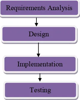
[image:23.595.243.377.205.373.2]The methodology procedure is to conduct the project in order to achieve the objectives are as shown in Figure 1.1. By completing each stage at its targeted time will guarantee that the project could be finished on time.
Figure 1.1: Flowchart of the project sequences.
1. Requirements Analysis - Find a research and literature review about the “Sensoring and Alerting System for Drivers” notification system on the internet, journal and book. From the research, we obtain information about the tools that can be used to complete this project. Watching you tube or video that relates to this project and gain more knowledge.
2. Design - In this stage, design the circuit “Sensoring and Alerting System for Drivers” by using PIC microcontroller and then try to do simulation of the circuit that is designed.
3. Implementation - Construct the hardware used in this project such as pic, IR sensor.
4. Testing - Process that covers all of the system that was designed and explained in this project. For this stage, the system of hardware and software able to operates well. The hardware component would be tested to see the result whether the project has achieve target or not.
Requirements Analysis
Design
Implementation
24
This chapter is separated into three chapters described below:
Chapter 1: Introduction
This chapter presents about the problem statement and objectives of the study together with as overview of the thesis.
Chapter 2: Literature Review
The existing approaches and methods of driver alerting system were discuss details in this chapter.
Chapter 3: Methodology
This chapter explain details about the recommendation method of tiredness detection on the components and equipment needed for the experiment will be presented.
Chapter 4: Result and Discussion
This chapter explain details about the Result and Analysis. The result obtained regarding the performance of the system in universal term and overall systems operation.
Chapter 5: Conclusion