Design and Development of
Non-Conventional Power Train
System
Principle Researcher:
lr .
.
SIVARAO SUBRAMONIAN,
P.ENG
Co-Researcher:
DR. BAGAS WARDONO
•
UNIVERSITI TEKNIKAL MALAYSIA MELAKA
•
ABSTRACT
ACKNOWLEDGEMENTS
the researchers
I
author would like to render his sincere thanks to the top levelmanagement of research and develop?Ient team in University Technical
Malaysia Melaka (UTeM) for funding this short term research project. The
author would also like to extend his sincere thanks to Professor Kadim Bin
Saudi, the Director of Centre f.or Research & Innovation Management (CRIM), Dr. Mohd. Rizal Salleh, the Dean of the Manufacturing Engineering
Faculty for extending their sincere help, guidance and support in completing
this project. Last but not least, the author would like to thank all the faculty
TABLE OF CONTENTS
Abstract
Acknowledgement
Table of Content
List of Figure
List of Table
List of Abbreviation
1. INTRODUCTION
1.1 Problem Statements
1.2 Objectives
1.3 Scopes of the Research
1.4 Hydraulic history and principles
1.4.1 Basic Hydraulic Theory
1.4.2 Basic Hydraulic Power System
1.4.3 Hydraulic accessories
1.5 Overview of the Hydraulic Component
1.5.1 Hydraulic Pump
1.5.1.1 Hydraulic Pump Theory
1.5.2 Hydraulic Motor
1.5.2.1 Factors Involving Hydraulic Motor
1.5.2.2 Selecting the Hydraulic Motor
1.5.2.3 Sizing the Hydraulic Motor
1.5.3 Control Valves
1.5.3.1 Ports and Position
1.5.3.2 Types of Valves
1.5.4 Hydraulic Fluid
1.5.4.1 Influential Factors involving the hydraulic fluid
2. LITERATURE REVIEW
3. METHODOLOGY
3.1 Introduction
3.2 Project Selection
3.3 Develop detail planning
3.4 Preliminary investigation conduct
3.5 Identify Parameters Involve
3.6 Hydraulic system analysis
3.7 Hydraulic circuit design
3.8 Hydraulic Transmission simulation
3.9 Simulation analysis
3.10 Analysis discussion
3.11 Conclusion
4. RESULTS AND DISCUSSION
4.1 Hydraulic Analysis
4.1.1 Hydraulic Transmission System A
4.1.1.1 Discussion on hydraulic transmission A
4.1.2 Hydraulic transmission System B
4.1.2.1 Analysis torque at 3500 Nm and power at 175Hp
4.1.2.2 Analysis on pipe pressure and fluid speed
4.1.2.3 Discussion on Hydraulic Transmission System B
4.1.3 Hydraulic Transmission System C
4.1.3.1 Analysis on torque at 5000Nm and power at 241Hp
4.1.3.2 Analysis at pipe pressure and fluid speed
4.1.3.3 Discussion on hydraulic transmission System C
4.1.4 Observation
4.2 Hydraulic Circuit design
4.2.1 Idling time
4.2.2 Forward motion
4.2.3 Reverse motion
4.2.4 Hydraulic equipments
4.3 Circuit analysis
5. CONCLUSION
5.1 Conclusion
5.2 Recommendation
REFERENCES
v
65
65
66
LIST OF FIGURES
1.1 Bernoulli's Principle 4
1.2 Figure example on how to calculate the force acting on pistons 5
1.3 Basic Hydraulic Power System 7
1.4 The head loss theory based on ping pong balls 12
1.5 Graph showing the relationship between pressure and flow rate in a
centrifugal pump. (Courtesy of The Warfighter Encyclopedia) 13 1.6 Basic pump characteristic curve of pressure head versus velocity head.
(Courtesy of The Warfighter Encyclopedia) 14
1.7 Graph shows the characteristic of a pump when speed is increased.
(Courtesy of The Warfighter Encyclopedia) 14
1.8 Graph shows the pressure versus flow rate in parallel operation.
(Courtesy of The Warfighter Encyclopedia) 15
1.9 Characteristic curve Vs velocity. (Courtesy of The Warfighter
Encyclopedia) 15
1.10
Ks
y
s
characteristic graph. (Courtesy of The Warfighter Encyclopedia) 16 1.11 Graph shows the pump operating curves with increasing hotwelllevel. (Courtesy of The Warfighter Encyclopedia) 17
1.12 The operation inside a impeller of the hydraulic pump 18 1.13 Schematic shows simple circuit to control cylinder extension and
retraction using a 4-port, 3-position spool valve 23
1.14 This cutaway view of a multiple-spool stack valve shows main
directional spools, internal flow passages, and auxiliary valves 24 1.15 Subbase-mounted valves simplify mounting and replacement
of valves because they can be removed and replaced without
disturbing system plumbing 25
3.1 Process flow diagram 39
4.1 The Hydraulic Transmission System A 47
4.2 Pipe pressure and fluid speed control 48
4.3 Hydraulic transmission system at 3500 Nm and 174Hp 50
[image:7.529.41.497.45.718.2]4.5 Hydraulic transmission system at 5000 Nm and 241Hp 54
4.6 Pipe pressure and fluid speed control 55
4.7 Hydraulic Transmission Circuit Design 59
4.8 The hydraulic transmission system in Idling time 60
4.9 The hydraulic transmission system in forward motion 61
4.10 The hydraulic transmission system in reverse motion 62
LIST OF TABLES
1.1
Table showing the classification and types of pumps 113.1
Table Equipment required for the Hydraulic Transmission system42
3.2
Gantt chart PSM I44
3.3
Gantt chart PSM II45
4.1
Hydraulic parameters value and observations57
[image:9.529.37.504.41.761.2] [image:9.529.54.509.44.637.2]LIST OF ABBREVIATIONS, SYMBOLS, SPECIALIZED
NOMENCLATURE
LBt Pound force
PSI Per square inch
ft2 feet square
. 2
m square inches
HL Head loss
PH Pressure Head
VH Velocity head
EH Elevation head
TH Total Head
NPSH- net positive suction head
Ksys system operating curve
Vs Velocity head
RPM
-
revolution per minuteMFP
-
main feed pumpMCP
-
main condensate pumpHP horse power
BFPA British Fluid Power Association
CHAPTER!
INTRODUCTION
Hydraulics is a topic of science and engineering dealing with the mechanical properties of liquids. Hydraulics is part of the more general discipline of fluid power. Fluid mechanics provides the theoretical foundation for hydraulics, which focuses on the engineering uses of fluid properties. Hydraulic topics range through most science and engineering disciplines, and cover concepts such as pipe flow, dam design, fluid control circuitry, pumps, turbines, hydropower, computational fluid dynamics, flow measurement, river channel behavior and erosion.
Hydraulic system is defined as force that is applied at one point is transmitted to another point using an incompressible fluid (Marshall Brain, 2000). Hydraulic system uses many liquids such as petroleum oils, synthetic oils and water. The first hydraulic fluid to be used was water because it is readily available. However, water has many deficiencies. It is already freezes, a relatively poor lubricant and tends to rust metal components. Hydraulic oils are far superior and hence are widely used in lieu of water.
In hydraulic system, it is consists of hydraulic pump, hydraulic motor and directional valves. These equipments are essential and provide the muscle to do the desired work. The hydraulic pump exhibit the fluid to be transmitted to the hydraulic motor where the motor will produces a torque resulting in a rotary motion. Hydraulic can provide a huge forces and torque to drive loads with utmost accuracy and precision. The interesting thing in hydraulic systems is the ability to apply force multiplication.
torque converter and a set of planetary gearsets to provide a range of torque multiplication, it operates the predominant form of the transmission system (Wikipedia, 2006). The multitude of parts, along with the complex design of the valve body, originally made of the automatic hydraulic transmissions much more complicated and expensive to build and repair than manual transmissions. Mass manufacturing and decades of improvements have reduced the cost. The automatic transmission system also needs high in fuel consumption and high in engine maintenance. Furthermore, once the gearbox is damaged, it is needs a high cost for repairing them due to the expensive parts and services.
The purpose of this project is to create a transmission system which only consists of hydraulic system. By removing the mechanical system in the transmission system,
we will only use the hydraulic system to provide movement and speed to the car.
The application that will be used to design the hydraulic transmission system will be fulfill the hydraulic system. It is known as hydrostatic transmission that has replaced the mechanical transmission system but the application only can used in heavy vehicles such as track; a type of tractor and the transmission needs a larger engine to be run. With the development of the hydraulic transmission system, maintenance cost can be reduced and a smaller yet compact engine can be developed. Hence it can reduce the cost of making an engine.
The selection of the hydraulic pump and motor will be studied and considered essentially to this project in order to find the suitable horsepower and torque which are equivalent to the automatic transmission system, suitable parameters are to be investigated and calculated. Furthermore, the fluid properties used as a medium to transmit the power to the motor also will be studied and included in this project.
1.1
Problem Statement
Based on the problems occurs in a present hydraulic transmission system and mechanical transmission of an automobile, there are few problems that contribute to implement this project. The problem statements as below:
(a) To create higher speed torque, greater engine capacity is required. For this, new designs are being developed to increase the engine capacity in order to meet the demand.
(b) Bigger engine require more space and critical economic consideration to save fuel consumption.
(c) It incurs higher cost in engine and attachment production.
(d) The mechanical transmission consist many mechanical associates which produces louder noise and power loss.
1.2
Objectives
The objectives for this project are:
(a) Simulate a transmission system circuit which is fully operated by hydraulic system.
(b) Observe and analyze the hydraulic capability in transmitting the power base on the existing system.
(c) To analyze the suitable parameters for the hydraulic transmission system. (d) Suggestion for development.
1.3
Scope of Research
1.4
Hydraulic History and Principles
Fluid power technology came on its own in the 17th century with the discovery of
Pascal's Law and in the 18th century with the discovery of Bernoulli's Principle.
These two findings form are the basic principles behind modern hydraulic power.
Pascal's Law- Pressure applied to a confined fluid is transmitted undiminished in all
directions. Pascal made this determination when he rammed a cork into a jug
completely full of wine and the bottom was broke out. Pascal deduced the pressures
were equal at the top and bottom of the jug. However, since the jug had a small area
at the top and a large area at the bottom, the bottom experienced a greater total force
due to its larger area.
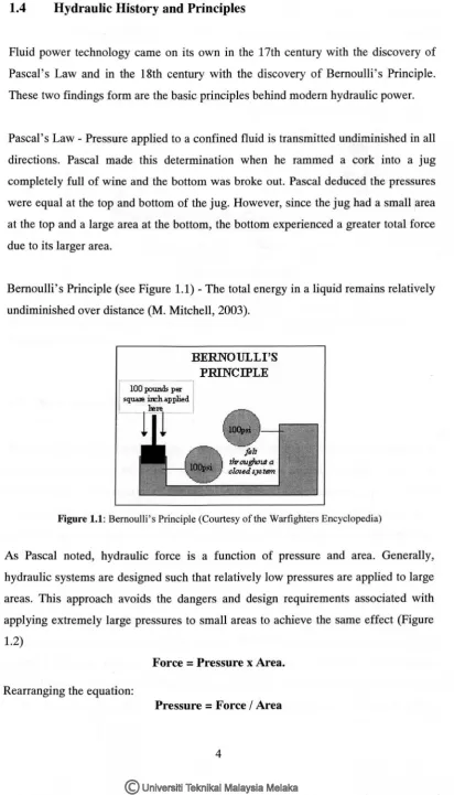
Bernoulli's Principle (see Figure 1.1)- The total energy in a liquid remains relatively
undiminished over distance (M. Mitchell, 2003).
lOOIXJWl,dsper squall! :ireh a.pplied
[image:14.527.71.484.54.776.2]BERNOULLI'S PRINCIPLE
Figure 1.1: Bernoulli's Principle (Courtesy of the Warfighters Encyclopedia)
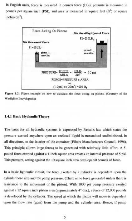
As Pascal noted, hydraulic force is a function of pressure and area. Generally,
hydraulic systems are designed such that relatively low pressures are applied to large
areas. This approach avoids the dangers and design requirements associated with
applying extremely large pressures to small areas to achieve the same effect (Figure
1.2)
Force
=
Pressure x Area. Rearranging the equation:Pressure
=
Force I AreaIn English units, force is measured in pounds force (LBt); pressure is measured in pounds per square inch (PSI), and area is measured in square feet (ft2) or square
inches (in2).
Force Acting On Pistons
The Rsslllling Upward Force
F1=20LBt
F2=200LBf
pisto:n2 2
a>ea=alin
PRESSURE= FORCE = 20L~ = 1 0 psi
AREA 2in2
FORCE=PRESSURE x AREA so.
( 1 Opsi) X ( 20in2) =200 lht
Figure 1.2: Figure example on how to calculate the force acting on pistons. (Courtesy of the
Warfighter Encyclopedia)
1.4.1 Basic Hydraulic Theory
The basis for all hydraulic systems is expressed by Pascal's law which states the pressure exerted anywhere upon an enclosed liquid is transmitted undiminished, in all directions, to the interior of the container (Filters Manufacturers Council, 1996). This principle allows large forces to be generated with relatively little effort. A 5-pound force exerted against a l-inch square area creates an internal pressure of 5 psi. This pressure, acting against the 10 square inch area develops 50 pounds of force.
[image:15.530.62.486.48.758.2]delivery is 1 gallon per minute (231 cu.in./min.) the cylinder piston will move at a
rate of 20 in.min. (231 cu.in./12 cu.in./min.).
The simplest hydraulic circuit consists of a reservou, pump, relief valve, 3-way
directional control valve, single acting cylinder, connectors and lines. This system is
used where the cylinder piston is returned by mechanical force. With the control
valve in neutral, pump flow passes through the valve and back to the reservoir. With
the valve shifted, oil is directed to the piston side of the cylinder, causing the piston
to move, extending the rod. If the valve is returned to neutral, the oil is trapped in the
cylinder, holding it in a fixed position, while the pump flow is returned to the
reservoir. Shifting the valve in the opposite direction permits the oil to pass through
the valve back to the reservoir. The relief valve limits the system pressure to a pre-set
amount.
A hydraulic system uses a double acting cylinder and a 4-way valve differs from the
single acting cylinder system in that the cylinder can exert force in both directions.
With the control valve in neutral, flow is returned to the reservoir. When shifted in
one direction, oil is directed to the piston side of the cylinder, causing the cylinder to
extend. Oil from the rod side passes through the valve back to the reservoir. If the
valve is shifted to neutral, oil in the cylinder is trapped, holding it in a fixed position.
When the valve is shifted in the opposite position, oil is directed to the rod side of the
cylinder, causing the cylinder to retract. Oil from the piston side passes through the
valve back to the reservoir. Cylinder extend force is a result of the pressure (psi)
times the piston area. Retract force is a result of the pressure (psi) times the area
difference between the piston minus the rod diameter.
Rotary hydraulic motor circuits are basically the same as cylinder circuits. Systems
may be uni-directional or bi-directional. The amount of rotary force (torque)
available from the motor is a function of pressure (psi) and motor size. Speed is a
function of flow and motor size.
All ·the systems described above are open center systems due to the oil flowing
through the control valve back to tank. Most systems are this type. Closed center
systems use control valves with the inlet port blocked and variable displacement
pumps. With the control valve in neutral, the pump is "de-stroked" to zero flow.
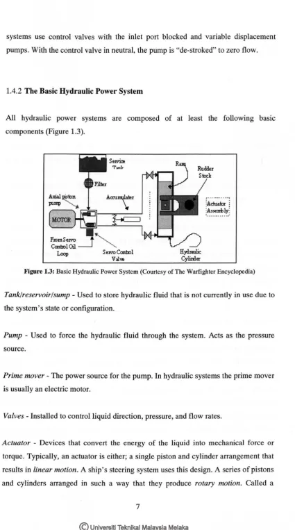
1.4.2 The Basic Hydraulic Power System
All hydraulic power systems are composed of at least the following basic
components (Figure 1.3).
S erro Conb:ol Valve
Rudder Steck
:Actuator ~
[image:17.527.70.496.9.773.2]:~~~~~(
Figure 1.3: Basic Hydraulic Power System (Courtesy of The Warfighter Encyclopedia)
Tank/reservoir/sump - Used to store hydraulic fluid that is not currently in use due to
the system's state or configuration.
Pump - Used to force the hydraulic fluid through the system. Acts as the pressure
source.
Prime mover - The power source for the pump. In hydraulic systems the prime mover
is usually an electric motor.
Valves- Installed to control liquid direction, pressure, and flow rates.
Actuator - Devices that convert the energy of the liquid into mechanical force or
torque. Typically, an actuator is either; a single piston and cylinder arrangement that
results in linear motion. A ship's steering system uses this design. A series of pistons
hydraulic motor, many of our gun mounts and missile launchers use these pumps to
train the gun or launcher.
Piping- Used to contain and direct hydraulic fluid from one point to another.
1.4.3 Hydraulic Accessories
In addition to the basic hydraulic power system components discussed, hydraulic systems may require additional control components:
Filters/strainers- Used to remove foreign particulate matter from hydraulic fluid that
could damage (by scratching close tolerance components) or clog the system.
Pressure regulator - A device that vents off or unloads hydraulic fluid from the high
pressure side (pump outlet) when the pressure in the system exceeds set point (design pressure). The unloaded fluid usually is returned to the low pressure side of the system or the sump. By unloading hydraulic fluid, pressure is reduced. When hydraulic pressure returns to set point, the regulator stops unloading. By constantly loading or unloading, the pressure regulator maintains the pressure at set point.
Accumulator - A device that acts as a hydraulic shock absorber for the system. It is basically consists of a container, divided into two sections by a flexible divider or membrane. One section is open to the hydraulic system's liquid and the other section contains a gas (often nitrogen) under an appropriate pressure. It is used to store a certain volume of hydraulic fluid under pressure. The liquid side experiences the same pressures as the fluid in the hydraulic system. When the hydraulic system experiences a sudden pressure increase, the effect is reduced or dampened by fluid in the accumulator compressing the gas on the other side of the membrane. When the system experiences a sudden pressure decrease, the gas forces fluid out of the accumulator to increase system pressure. The accumulator is designed to handle brief system transients, not system casualties or long term degradations.
Relief valve - A device that protects systems from excess pressure. A relief valve is
much the same as a pressure regulator in that it unloads excess pressure. However, a relief valve has a higher set point than the pressure regulator and only operates under abnormal conditions such as a failure in the pressure regulator.
Check valve - A device that permits flow in only one direction.
Sequence valve - A device that controls the sequence of operation of one or more other components.
Servo - A device that measures output or state such as the rotation of a motor or the
distance of travel of a piston in a cylinder. The servo's output is compared to a standard or other output signal. The results of the comparison are used to control a system's state or actions.
1.5
Overview on The Hydraulic Equipment
Before the implementation of the project, it is better to understand the equipments that will be needed for the transmission system. The basic hydraulic equipments will be introduced to get a better understanding on its function. These equipments are essential in order to generate the whole hydraulic circuit.
1.5.1
Hydraulic
PumpThere are two broad classifications of pumps as identified by the fluid power
industry:
(a) Dynamic pumps (non-positive displacement).
This type of pump generally used for low-pressure, high volume flow
applications. Because they are not capable with standing high pressures, only a
little is use in the fluid power field. Normally their maximum pressure capacity is
limited from 250 - 300 psi. This pump is primarily used for transporting fluids
from one location to another. There are 2 types of dynamic pumps which are the
centrifugal and the axial flow propeller pumps.
(b) Positive Displacement pumps.
This pump universally used for fluid power systems. As the name implies, a
positive displacement pump affects a fixed amount of fluid into the hydraulic
system per revolution of pump shaft rotation. Such pump is capable of
overcoming the pressure resulting from the mechanical loads of the system as
well as the resistance to flow due to friction. These are two features that are
desired of fluid power pumps. These pumps have the following advantages over
non-positive displacement pumps:
1. High-pressure capability (up to 12,00 psi)
n. Small, compact size
iii. High volumetric efficiency
iv. Small changes in efficiency throughout the design pressure range.
v. Great flexibility of performance.
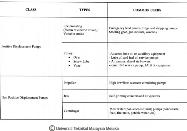
Table 1.1: Table showing the classification and types of pumps. (Courtesy of The Warfighter Encyclopedia)
CLASS TYPES COMMON USERS
Reciprocating
Emergency feed pumps, Bilge and stripping pumps (Steam or electric driven)
Variable stroke Steering gear, gun mounts, winches
I
Positive Displacement Pumps I
Rotary: -Attached lube oil on auxiliary equipment
•
Gear -Lube oil and fuel oil service pumps•
Screw Lobe -Air pumps, diesel air blowers•
Vane -some JP-5 service pump, AC & R equipment.Propeller High low/flow seawater circulating pumps
Non Positive Displacement Pumps Jets Self-priming eductors and air ejectors
1.5.1.1 Hydraulic Pump Theory
Hydraulic pump used the energy transfer as a method to show how the hydraulic pump works. In order to understand the energy transfer, some fundamental terms need to be explained. They are the head loss, pressure head, velocity head, elevation head, and total head.
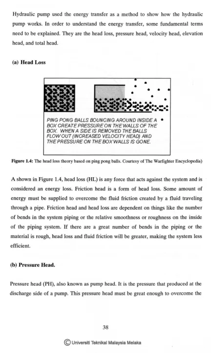
(a) Head Loss
•
[image:22.528.54.486.71.792.2]PING PONG BALLS EDUNCING AROUND INSIDE A • BOX CREATE PRESSURE ON THEWALLS OF THE BOX. WHEN A SIDE IS REMOVED THE BALLS FLOW OUT (INCREASED VELOCITY HEAD) AND THE PRESSURE ON THEBOXWALLS IS GONE.
Figure 1.4: The head loss theory based on ping pong balls. Courtesy of The Warfighter Encyclopedia)
A shown in Figure 1.4, head loss (HL) is any force that acts against the system and is considered an energy loss. Friction head is a form of head loss. Some amount of energy must be supplied to overcome the fluid friction created by a fluid traveling through a pipe. Friction head and head loss are dependent on things like the number of bends in the system piping or the relative smoothness or roughness on the inside of the piping system. If there are a great number of bends in the piping or the material is rough, head loss and fluid friction will be greater, making the system less efficient.
(b) Pressure Head.
Pressure head (PH), also known as pump head. It is the pressure that produced at the discharge side of a pump. This pressure head must be great enough to overcome the
head losses acting against it if the pump is going to move the fluid. Pressure head is
inversely proportional to velocity head.
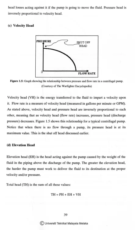
(c) Velocity Head
PRE SURE ~ SHUTOFF
~ ~HEAD
[image:23.527.53.497.39.792.2]FLOW RATE
Figure 1.5: Graph showing the relationship between pressure and flow rate in a centrifugal pump.
(Courtesy of The Warfighter Encyclopedia)
Velocity head (VH) is the energy transferred to the fluid to impart a velocity upon
it. Flow rate is a measure of velocity head (measured in gallons per minute or GPM).
As stated above, velocity head and pressure head are inversely proportional to each
other, meaning that as velocity head (flow rate) increases, pressure head (discharge
pressure) decreases. Figure 1.5 shows this relationship for a typical centrifugal pump.
Notice that when there is no flow through a pump, its pressure head is at its
maximum value. This is the shut off head discussed earlier.
(d) Elevation Head
Elevation head (EH) is the head acting against the pump caused by the weight of the
fluid in the piping above the discharge of the pump. The greater the elevation head,
the harder the pump must work to deliver the fluid to its destination at the proper
velocity and/or pressure.
Total head (TH) is the sum of all these values:
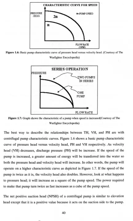
CHARACTERISTIC CURVE FOR SPEED
PRESSURE (FS!G)
n=PUMP SPEED
FLOWRA1E
[image:24.527.63.496.45.763.2](GPM)
Figure 1.6: Basic pump characteristic curve of pressure head versus velocity head. (Courtesy of The
Warfighter Encyclopedia)
PRESSURE
SERIES OPERATION
~WOPUIIAPS
IN SERIES
NE PUMP
FLOW RATE
Figure 1. 7: Graph shows the characteristic of a pump when speed is increased( Courtesy of The
Warfighter Encyclopedia)
The best way to describe the relationships between TH, VH, and PH are with
centrifugal pump characteristic curves. Figure 1.6 shows a basic pump characteristic
curve of pressure head versus velocity head, PH and VH respectively. As velocity
head (VH) decreases, discharge pressure (PH) will be increase. If the speed of the
pump is increased, a greater amount of energy will be transferred into the water so
both the pressure head and velocity head will increase. In other words, the pump will
operate on a higher characteristic curve as depicted in Figure 1.7. If the speed of the
pump is twice as it is, the velocity head also doubles. However, look at what happens
to pressure head; it will increase as a square of the pump speed. The power required
to make that pump turn twice as fast increases as a cube of the pump speed.
The net positive suction head (NPSH) of a centrifugal pump is similar to elevation
head except that it is a positive value because it acts on the suction side to the pump.