UNIVERSITI TEKNIKAL MALAYSIA MELAKA
LED BENDING MACHINE FIXTURE
Thesis submitted in accordance with the requirements of the
Universiti Teknikal Malaysia Melaka for the Degree of
Bachelor of Engineering Manufacturing (Robotics & Automation)
By
BEH TEIK SEONG
APPROVAL
This thesis submitted to the senate of UTeM and has been accepted as partial fulfillment of the requirements for the degree of Bachelor of
Manufacturing Engineering (Robotic & Automation).
The members of the supervisory committee are as follow:
………. Main Supervisor
DECRALATION
I hereby, declare this thesis entitled “LED Bending Machine Fixture” is the results of my own research
except as cited in the reference.
Signature :
Author’s Name : BEH TEIK SEONG
DEDICATION
ACKNOWLEDGEMENTS
I would like to offer thanks and deepest gratitude from the bottom of my heart for all the support, encouragement and inspirations I obtained through out the duration of this project. The help rendered to me priceless, be it from the smallest of its kind to the
largest. They include;
My supervising lecturer, En. Taufik of which we had a good working relationship, and who offered tremendous help and encouragement,
My family, who inspired me weather through the storm and carry on, My beloved, who kept me through it all,
Lecturers, and relevant personnel who helped in one way or
other;
ABSTRACT
This thesis represents a case study in designing a new machine fixture for the electronic industry. Of the various electronics component, the machine fixture will only focus on the LED sector. The new machine fixture would act as a ‘holder’ to hold the LED securely in the required position for the machine operation. In addition, it would be able to perform the bending and cutting operations simultaneously. By using the machine fixture, the user would be able to bend and cut the LED pin connector to the required shape and length. This design differs from the previous designs because it is able to perform the various tasks/operations on a short duration time. This machine fixture would vastly reduce the cycle time for producing LED’s in the current situation. Besides that, it has a higher precision, which directly means better quality in the product produced. The machine fixture would also help reduce the manufacturing cost for each LED. Since the machine fixture is semi-automated, we can reduce a substantial sum in the labor cost. The expenditure spent on quality control for part components can be reduced because the machine fixture would produce LED’s, which is of a standard quality range. Other than that, semi-skilled workers can be used to replace the skilled-workers whom are previously irreplaceable using this machine fixture. This fixture would also yield a higher production rate compared to the previous method. Finite element analysis that I use to analyze the structure of the machine fixture include Cosmos Xpress, Festo Pneumatic Software and Machine Design Tool
ABSTRAK
TABLE OF CONTENT
Abstract i
Abstract (Malay Version) ii
Dedication iii
Acknowledgement iv
Table of Content v
List of Table vi
List of Figure vii
CHAPTER I INTRODUCTION
1.1 Overview 1-3
1.2 Problems Statement 3-4
1.3 Objectives 5
1.4 Scope of Project 5-7
1.5 Thesis Outline 7-8
CHAPTER II LITERATURE REVIEW
2.1 Fixture
2.1.1 Definition 9
2.1.8 Advantages Of Fixtures 14-15 2.2 Fluid Power System 15-16 2.2.1 Pneumatic System 16-17 2.2.2 Electro-Pneumatic System Structure and Signal Flow 17-18 2.2.3 Pneumatic Cylinder 19-22
2.2.4 Valve 23-24
2.2.5 Flow Control Valve 25 2.3 Computer Aided Design (CAD) 26
2.3.1 SolidWorks 27-28
2.4 Programmable Logic Controller 28-31 2.4.1 PLC Programming 31-33 2.4.1.1 Logic Instruction 33-34 2.4.1.2 Graphic Programmer 34 2.5 Rolling Contact Bearings 35-37 2.6 Linear Motion Guide Slide 37-39 2.7 Mohr’s Circle 40-41
CHAPTER III METHODOLOGY
3.1 Introduction 42-43
3.2 Description of the Methodology 44-47
CHAPTER IV RESULT & DISCUSSION 48-49
4.1 Description of the Machine Fixture Design 450
4.7 Detail Drawing Stage 61-62 4.7.1 Detail Drawing of LED Bending Machine Fixture 62-63 4.7.2 Photo Galley of the LED Bending Machine Fixture 54-65 4.8 Documentation Stage 665 4.8.1 Mechanical Standard Part List 65-66 4.8.2 Electrical Standard Part List 67 4.8.3 Operation Flow Chart 68 4.8.4 Displacement Step Diagram 69 4.8.5 Electro-Pneumatic Diagram 69 4.8.6 PLC I/O Assignment 70 4.8.7 Electrical Wiring Diagram 71-73 4.8.8 Ladder Diagram 74
4.8.1 Mnemonic Code 75
4.8.2 Machine Operation Sequence 76-78 4.8.9 Machine Costing 78-79
4.9 Fabrication, Assembly and Verification Stage 80 4.10 Failure Analysis 80
CHAPTER V MACHINE FIXTURE ANALYSIS
5.1 Stress and Deformation Analysis 82-83 5.1.1 Design of A Critical Base Plate Analysis 83-85 5.1.2 Combined Stress and Mohr’s Circle 85-87 5.1.3 COSMOSXpress Analysis 87-90 5.2 Column Analysis 90-93 5.3 Pneumatic System Analysis 94 5.3.1 Cylinder Force 94-95
5.3.2 Load Ratio 95
Pneumatic Software 98-99 5.4 Operation Cycle Time Analysis 100-101 5.5 Executive Summary 102
CHAPTER VI SUGGESTION & CONCLUSION
6.1 Improvement at Machine Fixture 103-106
6.2 Conclusion 106-107
REFERENCE 108-109
APPENDICES
A Assembly & Part Drawing B Reference Table
LIST OF TABLES
Table 2.1 Input / output specification of KV series 31 Table 2.2 Recommended design life for bearing 37 Table 2.3 Data Specification of RSR-7N LM guide 39 Table 4.1 Mission Statement of LED Bending Machine Fixture 49 Table 4.2 Step in the design process 50
Table 4.3 Mechanical standard part list 65-66 Table 4.4 Electrical standard part list 67 Table 4.5 Programmer Logic Controller input/output assignment 70 Table 4.6 Total Machine Costing for LED Bending
LIST OF FIGURE
Figure 1.1 Size of LED for this project 6 Figure 1.2 Dimension requirement of the LED 7
Figure 2.1 Various aspect of fixture design 12 Figure 2.2 The various level from a control path for signal flow
From the signal ( input ) side to the work ( output ) side 18 Figure 2.3 Type of linear actuator 20 Figure 2.4 Data specification Pneumatic actuator that used in
LED Bending Machine Fixture 20-21 Figure 2.5 Mini pneumatic 5/2 way double solenoid 24
Directional control valve
Figure 2.6 Data specification of the solenoid valve 24 Figure 2.7 Data Sheet of the one way flow control valve 25 Figure 2.8 KV series programmable logic controller 31 Figure 2.9 Example of ladder diagram that programming 33
By OMRON CX programmable
Figure 2.10 Example Mnemonics code 34 Figure 2.11 Graphics programming console 34 Figure 2.12 Rolling element for ball and roller bearing 36 Figure 2.13 Data specification roller contact bearing 37 Figure 2.14 Construction of the LM guide 38 Figure 2.15 Load rating of the LM guide 39
Figure 4.4 Concept design 1 of the LED bending machine fixture 58 Figure 4.5 Main structure of the LED Bending Machine Fixture
(Concept Design 1) 58 Figure 4.6 Sliding mechanism (Concept Design 1) 58 Figure 4.7 Concept design 1 of the LED bending machine fixture 59 Figure 4.8 Main structure of the LED Bending Machine Fixture
(Concept Design 2 ) 60 Figure 4.9 Sliding mechanism (Concept Design 2) 60 Figure 4.10 Front view and side view of the LED Bending
Machine Fixture 62
Figure 4.11 Overall View of the LED Bending Machine Fixture 63 Figure 4.12 Main mechanism of the Machine Fixture 63 Figure 4.13 Overall View of the LED Bending Machine Fixture 64 Figure 4.14 Main mechanisms for bend and cut the LED pin
[image:14.612.99.475.71.708.2]Connector (Left), Wiring system inside control box (Right) 64 Figure 4.15 Bottom sides of the main base 65 Figure4.16 Operation Flow chats 68 Figure 4.17 Displacement step diagram 69 Figure 4.18 Electro Pneumatic Diagram 69 Figure 4.19 Electrical wiring diagram-Main diagram 71 Figure 4.20 Electrical wiring diagram-PLC Input 72 Figure 4.21: Electrical wiring diagram-PLC Output 73 Figure 5.1 Free body diagram of the critical part component 84 Figure 5.2 Result of the combined stress and Mohr’s circle
CHAPTER I
INTRODUCTION
1.1 Overview
The cost of designing and fabricating fixtures can amount to 10-20% of the total manufacturing system costs. To reduce manufacturing costs, a fixture system is designed to be competent in fixture as many work pieces as possible. In mass volume production, this can be achieved by fixture a large quantity of the same kind of work pieces. In low-to-medium volume production, however, improvement of the flexibility of fixture systems becomes a favorable way to reduce the unit cost of product. On modern manufacturing is able to achieve high productivity and to reduce unit cost. This necessitates work-holding devices to be efficient to increase the rate of loading and unloading to speed up the manufacturing cycle time. [4]
The employment of machine fixtures is an important aspect in workshop engineering, as their application on all but the simplest type of production smaller orders and tool room work. Fixtures are applicants this used in the manufacture or assembly to facilitate the operation to which they are applied. A fixture is the device that used to holds the work piece securely in the correct position great respect to machine/cutter during the operation. There is something a provision for setting that tool with respect to work piece /fixture but the tool is not guided as in Jig. Fixtures are often clamped on the machine table. From here, we also can add some operation functional such drilling, cutting or bending process on fixture devices to increase the production rate of the manufacturing process.
The name of this topic: Case Study in Designing a machine Fixture for
Electronic Industry. Of the various electronics component, the machine fixture will only
focus on the LED sector. The new machine fixture would act as a ‘holder’ to hold the LED securely in the required position for the machine operation. In addition, it would be able to perform the bending and cutting operations simultaneously. The project is started from initial stage which comes out with sketching design concept of the machine fixture following by the detail drawing of the machine fixture to determine the flexibility and stability of the machine structures and the structure of the machine fixture will be completed at the final stage. By using the machine fixture, the user would be able to bend and cut the LED pin connector to the required shape and length. This design differs from the previous designs because it is able to perform the various tasks/operations on a short duration time.
This machine fixture would vastly reduce the cycle time for producing LED’s in the current situation. Besides that, it has a higher precision which directly means better quality in the product produced. The machine fixture would also help reduce the manufacturing cost for each LED. Since the machine fixture is semi-automated, we can reduce a substantial sum in the labor cost. The expenditure spent on quality control for part components can be reduced because the machine fixture would produce LED’s which is of a standard quality range. In addition, the usage of machine fixture saves operator labor through simplifying operation process and makes possible the replacement of skilled workforce with semi-skilled labor, hence effecting substantial saving in labor cost which also translates into enhanced production rate. Furthermore, the use of well-structured machine fixtures with higher locating and clamping rigidity would allow for increase in bending and cutting speeds and feeds, thereby reducing time, hence improving production rate. Besides improving the productivity in terms of the rate of production it also decreases expenditure on quality control of part component as machine fixture facilitates uniform quality in manufacturing.
There are several important roles that should be considered for this project and they include:
a) Machine design
b) Design of machine element
c) Process manufacturing of the machine parts components
d) Applications of the electro-pneumatic system in machine fixture
e) Applications of the PLC to control the actuator and sequence process on machine fixture.
During implementation of the project, knowledge in mechanical, manufacturing and electrical engineering should be applied. During research, design and development of the machine, many factors will affect the alignment, mechanism and strength of material of machine. These factors must be detected and eliminated to make sure the machine function well. Several factors also must be taken into consideration, such as design for assembly (DFA) and design for manufacturing (DFM).
1.2 Problems Statement
Nowadays manufacturing plays an important role in achieving high productivity and reducing unit cost. This necessitates machine fixture to be efficient to increase the rate of loading and unloading or automated the machine fixture to speed up the manufacturing cycle time. To improve production rate, which also means reducing the cycle time of the manufacturing process, we need to analyze the machine fixture operated by operator to lower manufacturing lead-time and reduce the jam and breakdown time of the production. From here, the aim of this project is to study the machine fixture operative in electronic industry. So the responsibility on this project is to come out with a new design concept of the machine fixture to increase the productivity of LED components. From here, a new design with the concept of the LED
bending machine fixture, which is able to increase the productivity of the PCB board manufacturing industry, is going to produce.
Before producing the LED component as shown in figure below, operator needs a long cycle time to proceed, by using the jig fixture by manually to bend and cut the length of pin connector for LED component. The cycle time for complete process to produce LED as requirement below is more than 1 minute and operation sequence process by using that jig fixture is quite complex. From here, all of this phenomenon will reduce the production rate of the production and also the thorough time of the manufacturing process. This will contribute to low production quantity, which is below 50 000 unit per year.
Besides that, skilled worker must operate this jig fixture because only they can bend the shape of pin connector on requirement dimension. This situation will cause an increase in direct skilled labor required to operate the fixture. From here it will indirectly increase the production cost of the production because the factory needs to pay the skilled workers.
Other than that, LED produced manually by operator will increase the expenditure on quality control of part component as fixtures facilitate uniform quality in manufacturing. Sometimes operator cannot produce the shape of the LED as required and will damage the LED due to part defects. Therefore it will increase the production cost and affect the following processes.
If the jig and fixture is handled manually, it will damage the part easily. This is because of the human errors such as friction between the part and the machine elements. Therefore it will increase the maintenance cost. As a result the unit cost will be increased.
1.3 Objectives
• To design a flexibility machine fixture system that used to speed up the
manufacturing cycle process and to reduce the manufacturing cost of each LED.
• To bend and cut the LED pin connector to the required shape and length and able
to perform the various tasks/operations on a short duration time.
• To save operator labor through simplifying operation process and makes possible
the replacement of skilled workforce with semi-skilled labor.
• To decrease expenditure on quality control of machined parts as fixtures
facilitate uniform quality in manufacturing
1.4 Scope of Project
A structure of LED Bending machine fixture will be generated at the end of this project. It was designed based on requirement from PCB board electronic industry which bends and cuts the length of the LED pin connector in desired shape and dimension. Beside that this machine fixture needs to complete all sequence process in a fixed duration. The machine consists of three main mechanisms, which include: LED holding devices, bending mechanism and cutting mechanism. These three mechanisms will be combined to provide the function operation process to produce the LED on high production rate.
• The cycle time to complete process is lower than 20 sec per unit and production
quantity is 100,000 units per year.
• The machine fixture should meet all governments and industries safety standards.
The machine fixture must provide the safety cover and emergency stop button for safety requirement.
• This machine fixture must have low operating and maintenance cost with average time to clear the break down and the time to restart the operation process must lower than 10 minute.
• The LED bending machine fixture must easy to operate which simplifying
operation process and makes possible the replacement of skilled workforce with semi-skilled labor.
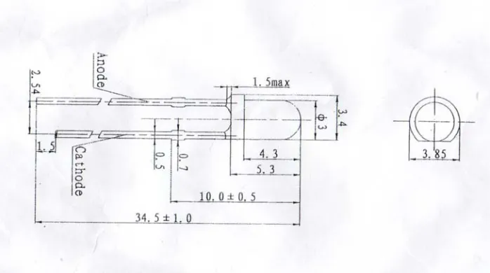
[image:23.612.139.488.440.635.2]• The machine fixture can only be used to bend and cut the specification size of LED below. If this fixture is used on another size of LED, we need to change the LED holding devices and make some adjustment of the mechanism.
Figure 1.1: Size of LED for this project
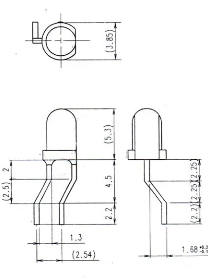
• The machine fixture is able to bend and cut the length of LED pin connector in
[image:24.612.205.410.151.425.2]requirement shape and dimension below.
Figure 1.2: Dimension requirement of the LED
1.5 Thesis Outline
This paper summarizes the latest studies in the electronic field of flexible LED bending machine fixture design and automation. First, chapter one (1) will describe a brief introduction on this research area that included discuss an overview of the project, problem statement, the content of this thesis and also the main objective of doing this project. Secondly, chapter two (2) where compound all information about jig and fixture, the design consideration of the LED Bending machine fixture, introduction of PLC (Programmable Logical Control), and mechanical devices that used in machine fixture