UNIVERSITI TEKNIKAL MALAYSIA MELAKA
Design and Development of Grass Cutting
Machine using DFMA Methodology
Thesis submitted in accordance with the requirements of Universiti Teknikal
Malaysia Melaka for the Bachelor’s degree in Manufacturing Engineering
(Manufacturing Design) with Honours
By
MOHD ISHAMMUDIN BIN MOHD YUNUS
Faculty of Manufacturing Engineering
UTeM Library (Pind.1/2007)
SULIT
TERHAD
TIDAK TERHAD
(Mengandungi maklumat yang berdarjah keselamatan atau kepentingan Malaysia yang termaktub di dalam AKTA RAHSIA RASMI 1972)
(Mengandungi maklumat TERHAD yang telah ditentukan oleh organisasi/badan di mana penyelidikan dijalankan)
(TANDATANGAN PENULIS) Alamat Tetap:
NO 453,Jln Hj Adnan, Kg Gching, 43900,Sepang, Selangor Darul Ehsan
Tarikh:
BORANG PENGESAHAN STATUS TESIS* UNIVERSITI TEKNIKAL MALAYSIA MELAKA
JUDUL:
_______________________________________________________________ _______________________________________________________________ SESI PENGAJIAN : _______________________
Saya _____________________________________________________________________
mengaku membenarkan tesis (PSM/Sarjana/Doktor Falsafah) ini disimpan di Perpustakaan Universiti Teknikal Malaysia Melaka (UTeM) dengan syarat-syarat kegunaan seperti berikut:
1. Tesis adalah hak milik Universiti Teknikal Malaysia Melaka.
2. Perpustakaan Universiti Teknikal Malaysia Melaka dibenarkan membuat salinan untuk tujuan pengajian sahaja.
3. Perpustakaan dibenarkan membuat salinan tesis ini sebagai bahan pertukaran antara institusi pengajian tinggi.
4. **Sila tandakan (√)
Design and Development of Grass Cutting Machine using DFMA Methodology
2007/2008
MOHD ISHAMMUDIN BIN MOHD YUNUS
(TANDATANGAN PENYELIA) Cop Rasmi:
DECLARATION
I hereby, declare this thesis entitled “Design and Development of Grass Cutting Machine using DFMA Methodology” is the results of my own research
except as cited in the reference.
Signature : ……..……….
Author’s Name : ………
Date : ………
APPROVAL
This thesis submitted to the senate of UTeM and has been accepted as fulfillment of the requirement for the degree of Bachelor of Engineering Manufacturing (Design). The
members of the supervisory committee are as follows:
………
Main supervisor
ABSTRACT
ABSTRAK
DEDICATION
ACKNOWLEDGEMENTS
First and foremost, I would like to express my highest appreciation to my supportive academic supervisor, Mr.Zolkarnain B. Marjom. His supervision and support that gave me truly helps during the period of conducting my thesis. His never-ending supply of valuable advice and guidance has enlightens me and deeply engraved in my mind.
Next, I would like to dedicate my thankfulness to the helpful of Mr. Saifudin, for his enthusiastic support and supervision of the thesis revision. I’m also happy to present my
gratefully acknowledge to Machinery laboratory technicians, who has been so warmth and kind to provide sincere assistance and good cooperation during the training period. Their co-operation is much indeed appreciated. In addition, I would like to convey thanks to FKP lecturers, for their assistance, which really spends their time to teach me a lots of knowledge regarding to the design development.
TABLE OF CONTENTS
Abstract……….i
Abstrak ………ii
Dedication………...iii
Acknowledgements……….iv
Table of Contents……….v
List of Figures……….ix
List of Tables………...xi
List of Sign and Symbol………xii
1. INTRODUCTION………...1
1.1General Introduction………...1
1.2Problem statement………2
1.3Objective………..3
1.4Scope of study………..3
2. LITERATURE REVIEW………...4
2.1Introduction………..4
2.2Design for Manufacturing and Assembly (DFMA)……….5
2.3Boothroyd Dewhurst DFA method………..7
2.4The Lucas DFA method………...8
2.4.1Functional Analysis………..10
2.4.2Handing Analysis………...10
2.4.3Fitting Analysis………...12
2.5The Guidelines of DFA………...13
2.5.1A DFA guideline………...13
2.5.3Design Guidelines for Insertion and Fastening……….14
2.6Types of Assembly………15
2.7DFA Process………..16
2.8Design for Manufacture Guidelines………...17
2.8.1General Principles of manufacturability………...17
2.9TeamSET………...19
2.10 Application of DFMA in industry………...21
2.10.1 Application of DFMA in aerospace industry……….21
2.10.2 Application of DFMA in automotive industry………...24
2.10.3 Application of DFMA in medical instrument industry………..26
3. METHODOLOGY………27
3.1Method of Study………27
3.2TeamSET process flow………..29
3.3TeamSET database process………....30
3.4DFA analysis for existing product……….34
3.4.1 Flow chart of existing product………...34
3.4.2 Flow chart of base part………...34
3.4.3 Flow chart of upper tunnel part………..35
3.4.4 Flow chart of lower tunnel part………..36
3.4.5 Detail drawing of existing product………37
4. RESULT AND ANALYSIS………...39
4.1Introduction of analysis………..39
4.2Draw design using SolidWork software………40
4.2.1 Detail drawing of first redesign……….40
4.2.2 Detail drawing of second redesign……….41
4.3Analysis using TeamSET software………42
4.3.1 DFA analysis for first redesign………..42
4.3.1.1Flow chart of first redesign………44
4.3.1.2Flow chart of upper tunnel part after first redesign………...44
4.3.1.3Flow chart of lower tunnel part after first redesign………...45
4.3.1.4Flow chart of base part after first redesign………46
4.3.1.5TeamSET analysis for first redesign………..47
4.3.2 DFA analysis for second redesign………...48
4.3.2.1Flow chart of second redesign………...49
4.3.2.2Flow chart of base structure part………...49
4.3.2.3Flow chart of cylinder blade part………...50
4.3.2.4Flow chart of tunnel part………50
4.3.2.5Flow chart of pulley system part………51
4.3.2.6TeamSET analysis for second redesign……….51
4.4Material and process selection……….53
4.4.1 Shaft blade and shaft connector……….53
4.4.2 Cylinder blade………54
4.4.3 Base structure……….55
5. DISCUSSION……….57
5.1Comparison of existing design with first and second redesign………..57
5.2Safeguards for prevent from mechanical hazards………..59
6. CONCLUSION & FUTURE WORKS ………...61
6.1Conclusion……….61
6.2Future works………..62
REFERENCES………63
APPENDIX
A Gantt chart for PSM 1 & 2
LIST OF FIGURE
1.1 The grass cutting machine 2
2.1 Flow chart of Lucas Hull method 9
2.2 Show DFA analysis 20
2.3 Show view of Longbow Apache Helicopter 23
2.4 Explode view of existing design of overhead luggage rack 24 2.5 Explode view of new design of overhead luggage rack 25
2.6 BagEasy III 26
3.1 Flow chart of Planning of the Study 28
3.2 The process flow in developing TeamSET database 29 3.3 The product maintaining projects, products and design scenarios 30
3.4 Product Breakdown Structure 31
3.5 Assembly Window 32
3.6 DFA analysis for assembly parts 33
3.7 A flow chart of existing product main part 34
3.8 A flow chart of base part 35
3.9 A flow chart of upper tunnel part 36
3.10 A flow chart of lower tunnel part 36
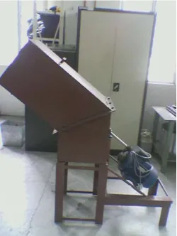
3.11 View of the existing product 37
3.12 TeamSET analysis for existing product 38
4.1 View of first redesign 40
4.2 View of second redesign 41
4.3 A flow chart of first redesign main part 44
4.6 A flow chart of base part 46
4.7 TeamSET analysis for improvement design 47
4.8 A flow chart of final design main part 49
4.9 A flow chart of base structure part 49
4.10 A flow chart of cylinder blade part 50
4.11 A flow chart of V-belt part 51
4.12 TeamSET analysis for second redesign 52
4.13 Drawing of shaft blade and shaft connector 53
4.14 View of cylinder blade 54
4.15 View of base structure 55
4.16 Cross section view of tunnel 56
4.17 Isometric view of tunnel 56
5.1 Part for accessories 59
5.2 View of the second redesign after installation accessories 60
6.1 Shows the comparison between existing product and second redesign
LIST OF TABLE
2.1 Lucas DFA method - Manual Handling Analysis 11 2.2 Lucas DFA method - Manual Fitting Analysis 12 2.3 Pilot's Instrument Panel Estimate Summary 23
4.1 Quantity List of a first redesign 43
4.2 Quantity List of a second redesign 48
LIST OF SIGN & SYMBOL
DFMA - Design for Manufacturing and Assembly DFA - Design for Assembly
DFM - Design of Manufacturing PDS - Product Design Specification QFD - Quality Function Deployment MA - Manufacturing Analysis
FMEA - Failure Modes and Effects Analysis DTC - Design to Target Cost
ASF - Assembly Flowchart
IPD - Integrated Product Development PEP - Engineering and Planning
IEFAB - Improved Extended Avionics Bay CAD - Computer Aided Design
CHAPTER 1
INTRODUCTION
1.1 General Introduction
Product lifecycle is being reduced drastically due to rapid changes in technology and customers requirements. The global marketplace is changing so rapidly that industrialist needs to adopt new strategies to respond customer’s requirement and in order to satisfy the market needs more efficiently and quickly. Many companies especially in Japan, USA and Europe have already started to implement techniques and tools that would enable them to respond more quickly to consumer’s demand in delivering high quality product at reasonable costs. The delay in time-to-market can be interpreted as a loss in profit (Alan F & Jan Chal, 1994).
Currently, the implementation of Design for Manufacturing and Assembly (DFMA) methodology are applied either manually or computer-aided. Most of the applied interested in implementing DFMA are hindered by lack of clear guidelines or procedures and no integration of isolated design and manufacturing teams. The advantages of the integration are to decrease the number of part design and indirectly to reduce cost and time. At the same time, it fulfills customer’s requirement. In this project, DFMA has been
1.2 Problem statement
[image:18.612.198.448.363.695.2]1.3 Objective
The main objective of this project is using DFMA methodology to design the new grass cutting machine and compare with the existing product. Beside that, other specific objectives include:
a) to develop the grass cutting machine; b) to design and analysis of original design;
c) to purpose grass cutting machine using DFMA method and TeamSET software;
d) to determine the optimum manufacturing and assembly method for low cost production with short production time.
1.4 Scope of study
a) Case study
A grass cutting machine has been selected as a case study for this project and had the potential to be redesign by applying the Design for Manufacturing and Assembly (DFMA) methodology. The tool selected for drawing the grass cutting machine is SolidWork. User can easily generate drawing from a model. Photorealistic rendering and animation that allow communicating how future products will look and perform early in the development cycle.
b) Design for Assembly (DFA)
CHAPTER 2
LITERATURE REVIEW
2.1 Introduction
2.2 Design for Manufacturing and Assembly (DFMA)
Design for Manufacturing and Assembly (DFMA) is a design philosophy used by designers when a reduction in part counts, a reduction in assembly time, or a simplification of subassemblies is desired. It can be used in any environment regardless of how complex the part is or how technologically advanced this environment may be. DFMA encourages concurrent engineering during product design so that the product qualities reside with both designers and the other members of the developing team (D-ESPAT, 2007).
According to Geoffrey Boothroyd, Professor of Industrial and Manufacturing at the University of Rhode Island, the practices now known as Design for Assembly (DFA), and Design for Manufacture (DFM) had their start in the late 1970's at the University of Massachusetts. Of all the issues to consider, industry was most interested in Design for Assembly. When developing a product, the maximum potential cannot be achieved without considering all phases of the design and manufacturing cycle. DFMA meets this demand by addressing key assembly factors before the product goes on to the prototype stage. These key factors are the product appearance, type, the number of parts required in the product, and the required assembly motions and processes (D-ESPAT, 2007).
The Term “DFMA” comes with the combination of DFA (Design for Assembly) and
then the design team will make revises as soon as possible at the early stage of the design period according this feedback information and determine the most satisfied design and technology plan.
The three goals in DFM are:
1. Increase the quality of new produces during the development period, including design, technology, manufacturing, service and so on.
2. Decrease the cost, including the cost of design, technology, manufacturing, delivery, technical support, and discarding.
3. Shorten the developing cycle time, including the time of design, manufacturing preparing, and repeatedly calculation.
DFA is considering and resolving the possible problems in the assembly process at the early stage of the design which can make sure the part will be assembled with high speed, low cost and productivity. DFA is a kind of design paradigm with which, the engineer use all kinds of methods such as analyze, estimating, planning and simulating to consider all the factors that will affect the assembly process during the whole design process; revise the assembly constructions to satisfied the characteristics and functions of the final products; and meanwhile, lower the cost as most as possible.
2.3 Boothroyd Dewhurst DFA method
In the history of DFMA, Ford and Chrysler use the DFM philosophy in their design and manufacturing process of the weapons, tanks and other military products. Dr. Geoffrey Boothroyd and Dr. Peter Dewhurst who founded the Boothroyd Dewhurst, Inc (BDI) in 1982 are the first persons doing the research job in this new technology at the beginning in the early 1970’s. Actually, the “DFMA” is a trademark of their company. They created
and developed the DFMA concept which is used in developing the products of their company --- DFMA software system. Currently these programs are used to help the design in almost all the industrial fields including circuit boards (G. Boothroyd & W. Knight, 1993), with manual assembly, with robotic assembly, and with machining. They also do a lot of work examining the economic justification of each design revision (G. Causey, 1999).
They created and developed the DFMA concept which is used in developing the products of their company such as DFMA software system. Currently these programs are used to help the design in almost all the industrial fields including circuit boards, with manual assembly, with robotic assembly, and with machining. They also do a lot of work examining the economic justification of each design revision.
2.4 The Lucas DFA method
Although the Boothroyd-Dewhurst method is widely used, it is based on timing each of the handling and insertion motions. Although tables of data are available, the most accurate numbers are compiled through time studies in particular factories.
The basic construction of Lucas DFA is very similar to the DFA of BDI, it is the result of the cooperation of Lucas Organization and the University of Hull in U.K. Now, the logic of Lucas DFA has been integrated in the engineering analysis software “TeamSet” which