SMART AUTOMATED HOME
MEGAT IZZUDDIN BIN MEGAT AB MANAP
“I hereby declared that I have read through this report and found that it has comply the partial fulfillment for awarding the degree of Bachelor of Electrical Engineering
(Control, Instrumentation & Automation)‖
Signature : ………
Supervisor’s Name : Jurifa Bt Mat Lazi
SMART AUTOMATED HOME
MEGAT IZZUDDIN BIN MEGAT AB MANAP
This Report Is Submitted In Partial Fulfillment of Requirements for the Degree of Bachelor in Electrical Engineering (Control, Instrumentation & Automation)
Faculty of Electrical Engineering Universiti Teknikal Malaysia Melaka
DECLARATION
―I hereby declared that this report is a result of my own work except for the excerpts that have been cited clearly in the references.‖
Signature : ………
DEDICATION
ACKNOWLEDGEMENTS
First of all, I would like to express my thankfulness to Allah S.W. T who has given me the strength, knowledge and capability to implement and complete my Projek Sarjana Muda and also to complete this report.
I would like to express my highest and foremost gratitude to my project supervisor, Puan Jurifa Bt Mat Lazi for her guidance, help and advices to complete this project. Next, I would like to thank Malaysian Coal Integrated Engineering Services (MCIE), the company which I had my industrial training attachment with for their sponsorship of equipments and devices which I used for my project. I would also like to thank the Faculty of Electrical Engineering (FKE), Universiti Teknikal Malaysia Melaka (UTeM) for giving me the opportunity to implement and complete my project.
ABSTRACT
ABSTRAK
TABLE OF CONTENTS
CHAPTER CONTENTS PAGE
TITLE PAGE i
DECLARATION ii
DEDICATION iii
ACKNOWLEDGEMENTS iv
ABSTRACT v
ABSTRAK vi
TABLE OF CONTENTS vii
LIST OF FIGURES xiii
LIST OF TABLES xv
LIST OF APPENDICES xvi
LIST OF ABBREVIATIONS xvii
1 INTRODUCTION
1.1 Project Background 1
1.2 Problem Statement 3
1.2.1 General Problem Statement 3 1.2.2 Detailed Problem Statement 4
1.3 Project Objective 4
1.4 Project Scope 5
2 LITERATURE REVIEW
2.1 Case study 7
2.1.1 The Home Depot Smart Home 7 2.1.2 The purpose of building the Home Depot Smart 8
Home at Duke
2.1.3 The Duke Smart Home Program 9 2.1.4 Benefits of the Duke Smart Home Program 10 2.1.5 Accessibility in The Home Depot Smart Home 12 2.1.6 Cooling Systems for The Home Depot Smart 12
Home
2.1.7 Daylighting 12
2.1.8 Fire Safety 13
2.1.9 Geothermal Pump 13
2.1.10 Indoor Air Quality Monitoring 13 2.1.11 Leadership in Energy and Environmental Design 13
(LEED)
2.1.12 Media-on-Demand 14
2.1.13 Photovoltaic System Design 14 2.1.14 Protecting Public Health – UV Disinfection 14
of Drinking Water
2.1.15 Recycling 15
2.1.16 Retractable Roof 15
2.1.17 RFID Technology 15
2.1.18 Security 16
2.1.19 Soundproofing and Acoustic Suggestions 16 2.1.20 Water Catchment, Purification/ Rainwater 16
Harvesting
Noise Filtering
2.1.22 Facial Recognition 17 2.1.23 Advanced HVAC Control and Artificial 17
Intelligence Controllers
2.1.24 LED Lighting 17
2.1.25 Residential Piezoelectric Energy Sources 17
2.1.26 Sensor Platform 18
2.1.27 Shower Heat Recovery 18
2.1.28 Sleep Monitoring 18
2.1.29 Home Automation 19
2.2 Conclusion 19
3 METHODOLOGY
3.1 Overview 20
3.1.1 Literature review 20
3.1.2 Design the modules and circuits 20
3.1.3 Simulate circuits 20
3.1.4 Redesign circuits 21
3.1.5 Purchase components 21
3.1.6 Assemble circuits 21
3.1.7 Test operation 21
3.1.8 Troubleshoot 21
3.1.9 Assemble the modules 22
3.1.10 Test operation 22
3.1.11 Improvements, modifications and additions 22
3.1.12 Analysis 22
3.1.13 Connect the assembled modules 22
3.1.14 Test operation 23
3.2 Flowchart 24
3.3 Gantt chart 26
4 PROJECT BACKGROUND
4.1 Introduction 27
4.1.1 Smart Home 27
4.1.1.1 Functions of smart home system 28 4.1.1.2 Benefits of smart home system 29
4.2 Project Background 30
4.2.1 Indoor Lighting 30
4.2.1.1 Overview 30
4.2.1.2 Design 30
4.2.1.3 Circuit 32
4.2.1.4 Hardware and software 33
4.2.2 Outdoor Lighting 34
4.2.2.1 Overview 34
4.2.2.2 Design 34
4.2.2.3 Circuit 35
4.2.2.4 Hardware and software 38
4.2.3 Indoor Ventilation 39
4.2.3.1 Overview 39
4.2.3.2 Design 39
4.2.3.3 Circuit 41
4.2.3.4 Hardware and software 42
4.2.4 Garbage disposal 44
4.2.4.1 Overview 44
4.2.4.2 Design 45
4.2.4.4 Hardware and software 46 4.2.5 Garage and car park 50
4.2.5.1 Overview 50
4.2.5.2 Design 50
4.2.5.3 Circuit 53
4.2.5.4 Hardware and software 53
4.2.6 Events alert 58
4.2.6.1 Overview 58
4.2.6.2 Design 58
4.2.6.3 Circuit 59
4.2.6.3.1 Water Level Sensor 59 4.2.6.3.2 Heat Sensing 61 4.2.6.3.3 Smoke Sensor 62 4.2.6.3.4 Buzzer Interval 64 4.2.6.4 Hardware and software 65
4.2.7 Garden Management 68
4.2.7.1 Overview 68
4.2.7.2 Design 68
4.2.7.3 Circuit 69
4.2.7.4 Hardware and software 70
4.3 Components 71
4.3.1 Programmable Logic Controller (PLC) 71 4.3.1.1 Introduction to PLC 71
4.3.1.2 Features of PLC 72
4.3.1.3 Comparing PLC with other control 73 systems
4.3.1.4 Programming 75
4.3.2 Omron ZEN 76
4.3.2.2 Programming 76
4.3.2.3 Functions 77
4.3.2.4 Expansion 77
4.3.2.5 Support software 78 4.3.3 Integrated circuit (IC) 79
4.3.3.1 Introduction 79
4.3.3.2 History of ICs 79
4.3.3.3 Advantages of ICs 80 4.3.3.4 Popularity of ICs 80 4.3.3.5 Classifications of ICs 80
4.3.4 555 Timer IC 81
4.3.4.1 Introduction 81
4.3.4.2 Inputs of 555 83
4.3.4.3 Outputs of 555 84
4.3.4.4 555 Astable 84
4.3.5 741 Op-Amp IC 85
4.3.5.1 Introduction 85
4.3.5.2 Definition of 741 pin functions 86 4.4 Project Costs & Expenses 87
5 RESULT & DISCUSSION
5.1 Result 89
5.2 Discussion 90
5.2.1 Problems & Challenges 90
6 CONCLUSION & RECOMMENDATIONS
6.1 Recommendations 92
REFERENCES 94
APPENDICES 95
LIST OF FIGURES
FIGURE TITLE PAGE
1.1 Block Diagram of control system using PLC and IC 1
2.1(a) The Home Depot Smart Home 7
3.2 Project flow chart 24
3.3 Gantt chart 26
4.1(a) A smart home system 28
4.2.1(a) Block diagram for Indoor Lighting 30 4.2.1(b) Assembled circuit for the Indoor Lighting 32 4.2.1(c) Light dimmer circuit using PWM control method 32 4.2.2(a) Block diagram for Outdoor Lighting 34 4.2.2(b) Assembled circuit for the Outdoor Lighting 35 4.2.2(c) IC 555 Timer pin allocations 35 4.2.2(d) Internal circuit for IC 555 Timer 36 4.2.2(e) Light/dark sensing circuit for Outdoor Lighting 36 4.2.3(a) Block diagram for Indoor Ventilation 39
4.2.3(b) Wheatstone Bridge 40
4.2.3(e) 12VDC CPU fan rated at 0.13A 43
4.2.3(f) Temperature display unit 43
4.2.4(a) Block diagram for garbage disposal 45 4.2.4(b) Concept diagram for garbage disposal 45 4.2.4(c) Ladder diagram for overall Garbage Disposal module 48 4.2.4(d) Inductive proximity sensor used for platform position 48 4.2.4(e) AC Synchronous motor used for platform rotation 49 4.2.5(a) Concept diagram for garage and car park 50 4.2.5(b) Block diagram for garage and car park 51 4.2.5(c) Limit switch and triangular marker 52
4.2.5(d) Rotating platform 52
4.2.5(e) Optical distance sensor 54
4.2.5(f) Ladder diagram for garage door 56 4.2.5(g) Ladder diagram for rotating platform 57 4.2.6(a) Block diagram for Events Alert 58 4.2.6(b) Assembled circuit for Water Level Sensor 59 4.2.6(c) Water Level Sensor circuit for Events Alert 60 4.2.6(d) Assembled circuit for Heat Sensing 61 4.2.6(e) Heat Sensing circuit for Events Alert 61 4.2.6(f) Assembled circuit for Smoke Sensor 62 4.2.6(g) Smoke Sensor circuit for Events Alert 63 4.2.6(h) Assembled circuit for Buzzer Interval 64 4.2.6(i) Buzzer Interval circuit for Events Alert 64 4.2.7(a) Block diagram for Garden Management 68 4.2.7(b) Ultrasonic pest repellant circuit for Garden Management 69 4.3.1(a) PLC and input/output arrangements 71
4.3.1(b) Control Panel with PLC 72
4.3.2(a) Multi function and space saving features 76
4.3.2(b) Programming the Omron ZEN 76
4.3.2(c) Expansion units 77
4.3.3 Integrated circuit 79
4.3.4(a) Actual pin arrangements 81
4.3.4(b) Example circuit symbol 83
4.3.4(c) 555 Astable output, a square wave 84
4.3.4(d) 555 Astable circuit 85
4.3.5 741 Op Amp pin functions 86
5.1 Completed project 89
LIST OF TABLES
TABLE TITLE PAGE
LIST OF APPENDICES
APPENDIX TITLE PAGE
A UTeMEX poster 96
LIST OF ABBREVIATIONS
ABBREVIATIONS MEANING
CCTV Closed circuit television
DC Direct current
AC Alternating current
IC Integrated circuit
LCD Liquid crystal display
LDR Light dependant resistor
LED Light emitting diode
PLC Programmable logic controller
PIC Programmable interface controller
PWM Pulse Width Modulation
NO Normally open
NC Normally close
CHAPTER 1
1.1 Project Background
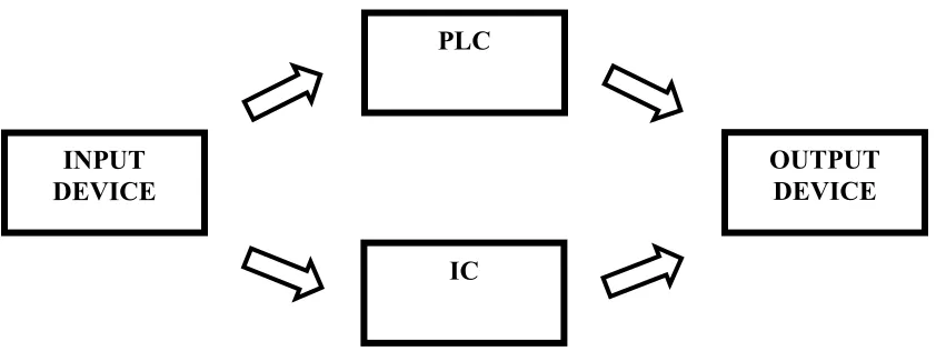
[image:20.612.88.509.204.362.2]This chapter provides the necessary background for this project, which explains the basic principle of PLC and IC control system.
Figure 1.1: Block Diagram of control system using PLC and IC
To create a control system, it must have 3 basic components which are input, process and output. The process consists of the PLC and IC which acts as input signal processing device to control the output. A brief introduction to the concept of application is given to provide basic understanding of this project.
The input device comes in the form of ordinary on/off limit switches, push buttons, variable resistors, photo-electric sensors, proximity sensor, light dependent resistors (LDR) and thermistors. These devices provide the activation signal in the form of analog or digital signal to the control unit.
The controller part which is the PLC and the IC acts as the primary control unit for this project. In this system, the PLC controller used is the Omron ZEN micro PLC unit. The input signals are transmitted digitally into the PLC and an appropriate
INPUT DEVICE
PLC
IC
―decision‖ will be made by the PLC according to the programmed ladder logic diagram. The PLC will then produce a digital signal in the form of relay output. The PLC is chosen over PIC to provide control for this project due to its multiple inputs and output arrangements and also its easy and user friendly programming using ladder logic diagram. The key feature for the PLC that is used is the built in daily, weekly and monthly timer capability which provides useful control for time controlled operation.
The IC is used for analog signal processing which involves decision making through logic gates combination and comparing two or more sets of input signals. There are two main advantages of ICs over discrete circuits which is the cost and performance. Cost is low because the chips, with all their components, are printed as a unit by photolithography and not constructed a transistor at a time. Performance is high since the components switch quickly and consume little power, because the components are small and close together.
For this project, the control is divided into two control devices which are the PLC and the IC. The purpose for this design is to fully utilize the advantages of both devices. The PLC has the advantage of easy programming, multiple relay outputs and enables systematic & organized wiring to be implemented. The IC on the other hand has the advantage of miniature size, low costs and provides tons of function according to the circuit it is connected. By combining two forms of these widely used devices, a good and reliable control system can be created to cater the project’s needs.
The output device will be in the form of relays, buzzer, DC motors, tweeter, lights, LEDs and fans. These devices receive activation signal from the PLC, IC or directly from the input device and perform various functions including illumination, cooling and etc.
This project like all others is created to solve problems that we humans encounter everyday. Upon completion of this project, the problems that we face will hopefully be solved or at least reduced. To make it easier to explain regarding the problem statements, they are divided into two parts, which is general aspect and detailed according to the system arrangements
1.2.1 General Problem Statement
There is no training kit that emphasizes the combination between PLC and electronics based circuits.
Most training kit available focuses on industrial system but not home automation system.
Available home automation has limited control over devices/system and costly.
1.2.2 Detailed Problem Statement
For the indoor lightings, the lights switches are located far away, not easily to access locations and the lights cannot be dimmed.
The outdoor lights needs to be turned on and off manually at day & night and sometimes the occupant forgot to turn them off. This causes wastage in electricity bills.
The temperature inside (indoor) are hot and unpleasant. The hot/warm air is trapped inside house due to poor ventilation
The occupant missed the weekly garbage collection time and the garbage spilled when bringing it outside the house. Furthermore, the odor from the garbage attracts flies & disease.
Plants at the garden die due to lack of watering and the gardens are infected by pests.
Accidentally hit the garage wall/children while reversing the vehicle and sometimes the occupant forgets to close the garage door
House does not have fire and flood warning system.
1.3 Project Objective
The objective of this project is to design & construct a control system
which consists of home automation and lighting control that can be used for various purpose especially teaching & learning and home application.
The lighting control is used to control the illumination and brightness for
1.4 Project Scope
Scope and limitations for this project:
Design and construction of a control system consist of home automation and lighting control.
Constructed using PLC, Electronic circuits, DC motors, sensors, switches, relays etc.
The model design & construction consists of small scale model that represents the connection and function of the system.
System powered by DC source through switching power supply and voltage regulators.
Lighting i. Indoor ii. Outdoor Home automation
i. Ventilation (Indoor) ii. Garbage disposal iii. Garden management iv. Garage/car park