‘I admit that read this thesis and in my opinion this thesis was satisfied from the aspect of scope and quality for the purpose to be awarded Bachelor of Mechanical
engineering (Automotive)’
Signature : ……… Name of Supervisor 1 : ……… Date : ………
DESIGN AND FABRICATE CHASSIS FOR PERSONAL ELECTRIC VEHICLE FOR UTEM
MOHD. FAISAL BIN ABDUL MANAS
The PSM (Projek Sarjana Muda) report is considered as one of the essential for student to compete their bachelor program in Mechanical (Automotive)
Faculty of Mechanical Engineering Universiti Teknikal Malaysia Melaka
ii
“I hereby declare that the work in this report is my own except for summaries and quotations which have been duly acknowledged”
iii
ACKNOWLEDGEMENTS
Firstly, my deepest gratitude to Allah S.W.T because of His will, I have done for study and conduct Projek Sarjana Muda and completely finish this thesis. A special gratitude is forwarded to my parents and family whose supports and prayers have been endless during a long period of my studies.
I would like to offer my heartfelt thanks to my academic supervisor, Dr. Muhammad Zahir bin Hassan for unmatched guidance; invaluable advice and knowledge during the course of this project and contributed a great amount of time and effort for making this Projek Sarjana Muda successfully done.
My sincere thanks to my group members of personal electric vehicle project; Omar bin Rozani, Muhammad Aizuddin bin Othman and Muhammad Hazwan bin Md Jamal whom always working together, sharing the knowledge and help me along the project period. My deepest appreciation is forwarded to my housemates here in Melaka, and to all my classmates in 4 BMCA for the great time as final year students.
iv
ABSTRACT
v
ABSTRAK
vi
TABLE OF CONTENT
DECLARATION ii
ACKNOWLEDGEMENT iii
ABSTRACT iv
TABLE OF CONTENTS vi
LIST OF TABLES ix
LIST OF FIGURES x
LIST OF SYMBOLS xii
LIST OF ABREVIATIONS xiii
LIST OF APPENDICES xiv
CHATER 1 INTRODUCTION 1
1.1 Overview 1
1.2 Problem Statement 2
1.3 Aim, Objective and Scope 3 1.4 Organization of Thesis 4
CHAPTER 2 LITERATURE REVIEW 5
2.1 Introduction 5
2.2 Historical Background of Electric Vehicle 5
2.2.1 The Early Years 5
2.2.2 The Middle Years 7
2.2.3 Developments towards the End of 20th 8 Century
vii
2.4 Chassis of Electric Vehicle 10 2.4.1 Chassis Requirement 11 2.4.2 Chassis Strength and Rigidity 12 2.4.3 Chassis/Body Stability 14
2.4.4 Chassis Design 14
2.4.5 Suspension 15
2.5 Handling System 15
2.6 Chassis Material 16
2.6.1 Steel Material 17
2.7 Finite element analysis 19
2.8 Summary 19
CHAPTER 3 METHODOLOGY 21
3.1 Flow Chart of the Project 21 3.2 Research for Chassis Design and Material 23
Selection
3.3 Designing Process 24
3.5 Small Scale Modeling 25
3.6 Fabricating Process 26
CHAPTER 4 ANALYSIS AND RESULT 27
4.1 Finite Element Analysis 27
4.1.1 Define Load 28
4.1.2 Bending Stress Analysis 29
4.1.3 Analysis Result 30
4.2 Final Result 33
CHAPTER 5 DISCUSSION 37
5.1 Design Modification 37
viii
CHAPTER 6 CONCLUSION AND RECOMMENDATION 50
6.1 Conclusion 50
6.2 Recommendation 51
REFERENCES 52
ix
LIST OF TABLES
CHAPTER 2
Table 2.1 Comparison of Material (tectonproducts.com) 17 Table 2.2 Carbon Percentage and Properties (ejsong.com) 18 Table 2.3 Carbon Percentages in Various Steel Applications 18
(ejsong.com)
CHAPTER 4
Table 4.1 Material Properties of Low Carbon Steel 28
Table 4.2 Result of analysis 32
CHAPTER 5
x
LIST OF FIGURES
CHAPTER 2
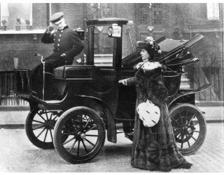
Figure 2.1 New York taxi cab in about 1901, a battery 6 Electric vehicle (Larminie and Lowry, 2003)
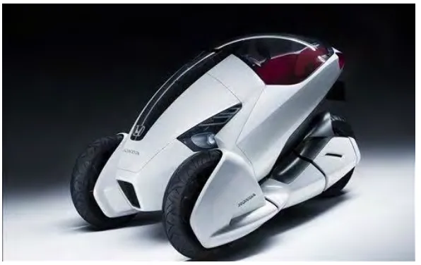
Figure 2.2 The Honda 3R-C three wheeled battery electric 9 (dieselstation.com, 2010)
Figure 2.3 Meredian Energy and Mitsubishi New Zealand 10 embarked on a nationwide trial of the iMieEV
electric vehicle from January to April 2009 (gm-volt.com, 2009)
Figure 2.4 A hollow cylinder under torsion and bending 12 loads (Larminie and Lowry, 2003)
CHAPTER 3
Figure 3.1 Flow chart of the whole project 22 Figure 3.2 3-wheeler (Wikipedia, 2006) 23 Figure 3.3 Final drawing of chassis 24
Figure 3.4 Small scale model 25
Figure 3.5 Chassis after welding process 26
CHAPTER 4
Figure 4.1 Location of applied load and constraint 29 for bending stress analysis
xi
CHAPTER 5
Figure 5.1 Seat illustration 38
Figure 5.2 Rendering drawing 38
Figure 5.3 Side view and perspective drawing of PEV 39 Figure 5.4 Chassis for 3-wheeled PEV 39 Figure 5.5 Assembly drawing of 3-wheeld PEV 40 Figure 5.6 Chassis design for 4-wheeled PEV 40 Figure 5.7 Complete drawing of 4-wheeled PEV 41
Figure 5.8 Sketching 42
Figure 5.9 Chassis design for new design of 3-wheeled PEV 43 Figure 5.10 Final design of chassis of PEV 44 Figure 5.11 Bending stress analysis of chassis 45 Figure 5.12 Zone of maximum von misses stress occurs 46 Figure 5.13 Graph of applied load against maximum von 48
misses stress
xii
LIST OF SYMBOLS
σ Maximum bending stress
w Uniform weight/length
L Length
𝑟₀ Radius
I second moment of area
δ Maximum deflection
E Young’s modulus
T Torque
J Polar second moment of area
xiii
LIST OF ABREVIATIONS
2D two-dimensional 3D three-dimensional
AISI American Iron and Steel Institute BEV battery electric vehicle
EV electric vehicle
FEA Finite Element Method FEA Finite Element Analysis
iMiEV Mitsubishi Innovative Electric Vehicle PEV personal electric vehicle
Fe Iron
xiv
LIST OF APPENDICES
Appendix A Sketching of the PEV 57
Appendix B Gantt chart PSM 1 58
Appendix C Gantt chart PSM 2 59
1
CHAPTER 1
INTRODUCTION
1.1
Overview
Electric vehicles (EV) enabled by high-efficiency electric motors and controllers and powered by alternative energy sources provide the means for a clean, efficient, and environmentally friendly urban transportation system. Electric vehicles have no emission, having the potential to curb the pollution problem in an efficient way (Husain, 2003). EVs were designed to do whatever was wanted in the past and can be designed and refined to do whatever is needed in the future (Leitman and Brant,2009).
There are many types of electric vehicles that used today, but this project is focused on the battery electric vehicle type. Deeply, this thesis points to design and fabricate the chassis and body of the electric vehicle. To design an electric vehicle, we should know what the major parts are in an electric vehicle. The battery electric vehicle has the propulsion system that contains electric battery, electric motor and controller; which combined with the body and chassis (Leitman and Brant, 2009).
2
researching, sketching, 3D software drawing, software prototyping and so on before the design is able to fabricated.
1.2
Problem Statement
Environmental as well as economical issues provide a compelling impetus to develop clean, efficient, and sustainable vehicles for urban transportation. Environmental technology or green technology is the application of the environmental science to conserve the natural environment and resources, and to curb the negative impacts of human involvement. One of focus area in green technology is energy and that includes the development of the alternative fuel or recycles energy. When people continue to exploit the earth for natural resources, they are increasingly aware of the damage caused by their actions. In the last century, people increasingly realize how serious environmental damage due to their actions and this makes them increasingly trying to rectify this situation. Since 70% of the sources of air pollution caused by fossil fuel use, it is logical for people to limit consumption of fossil fuels, particularly oil.
One of the main reasons the oil is excavated from the earth is to use as fuel of transportation vehicles. Apart from pollution sources, fuel oil is available in limited amounts. That would be up at a moment when the earth will run out of oil and this will cause problems to the transport system. Scientists and researchers are realizing that transportation vehicles such as trucks and cars do not need oil alone, but there are other fuel options. Due to this, various fuel options have been developed to replace oil. Among the fuels that have the opportunity to be developed as bio-fuel, electricity and hydrogen.
3
another with the aid of the motoring vehicle. This will require more time and energy to those who had walked. In the case, an eco-design mobility that can help the movement from one place to another place in faster and save energy should be created.
The best solution for these problems is to design and fabricate the first personal electric vehicle (PEV) for UTeM. As a summary, the problem statements for this project are:
i. The need of green technology ii. Efficiency
iii. Eco-design iv. Mobility device
1.3 Aim, Objectives and Scope
The overall aim of this project is to develop the first UTeM’s personal electric vehicle (PEV). In brief, this project is focus on design and fabricates the chassis of the personal electric vehicle. It focus on the study of chassis design, materials selection for chassis, chassis fabrication and finally to conduct Finite Element Analysis (FEA).
The main objectives for this project are as follow:
i. To design and fabricate UTeM’s first personal electric vehicle chassis.
ii. To choose material to manufacture chassis.
4
The project of personal electric vehicle for Universiti Teknikal Malaysia Melaka is doing in group of 4 members. The other members of the group are focusing on brake system, propulsion system and vehicle simulation.
1.4 Organization of Thesis
The remainder of this thesis is compromised of 3 further chapters as summarized below.
Chapter 2: A review of literature relevant to the present study comprising the general study of electric vehicle, chassis design, materials for the chassis and Finite Element Analysis.
Chapter 3: The methodology, comprising the process of conducting the project from the beginning till the end of the project.
Chapter 4: Result and analysis of this project.
Chapter 5: Discussion about the result and whole project.
5
CHAPTER 2
LITERATURE REVIEW
2.1 Introduction
The subject of electric vehicle chassis design has generated a considerable volume of literature which includes a number of theories that have been formulated. Studies on electric vehicle chassis design involve two major areas of study; which are chassis components and materials selection. The chapter begins with the introduction of electric vehicle, to give overview about the electric vehicle before go further to the chassis design studies which has more explanation of information and theories. This chapter also including the literature of the materials and finally and a summary of the existing approaches is provided together as the guideline in design process of the personal electric vehicle.
2.2 Historical Background of Electric Vehicle
2.2.1 The Early Years
6
through steam power, because the laws of electromagnetic induction, and consequently, electric motors and generators, were yet to be discovered. Faraday demonstrated the principle of the electric motor as early as in 1820 through a wire rod carrying electric current and a magnet, but in 1831 he discovered the laws of electromagnetic induction that enabled the development and demonstration of the electric motors and generators essential for electric transportation.
[image:21.595.208.431.379.553.2]The first electric vehicles of the 1830s used non-rechargeable batteries. Half a century was to elapse before batteries had developed sufficiently to be used in commercial electric vehicles. By the end of the 19th century, with mass production of rechargeable batteries, electric vehicles became fairly widely used. Private cars, though rare, were quite likely to be electric, as were other vehicles such as taxis. An electric New York taxi from about is shown in Figure 2.1 (Larminie and Lowry, 2003).
Figure 2.1 New York taxi cab in about 1901, a battery electric vehicle (Larminie
7
2.2.2 The Middle Years
At the start of the 20th century electric vehicles must have looked a strong contender for future road transport. The electric vehicle was relatively reliable and started instantly, whereas internal combustion engines were at the time unreliable, smelly and needed lighting and the thermal efficiency of the engines was relatively low (Larminie and Lowry, 2003). With oil and gasoline prices again approaching their 1970s levels, everyone lost interest in electric vehicles, and the capital coffers of the smaller electric vehicle manufacturers were simply not large enough to weather the storm. Even research programs were affected. From mid-1983 until the early 1990s, it was as if everything having to do with electric vehicles suddenly fell into a black hole; there were no manufacturers, no books, not even many magazine articles (Leitman and Brant, 2009).
According Larminie and Lowry (2003), the reasons for the greater success to date of internal combustion engine vehicles are easily understood when one compares the specific energy of petroleum fuel to that of batteries. The specific energy of fuels for internal combustion engines varies, but in around 9000 Whkg-1, whereas the specific energy of a lead acid battery is around 30 Whkg-1. Besides that, some major problem that arises with batteries is the time it takes to recharge them. Even when adequate electrical power is available there is a minimum time, normally several hours, required to recharge a lead acid battery, whereas 45 litres of petrol can be put into a vehicle in approximately one minute. Yet another limiting parameter with electric vehicles is that batteries are expensive.
8
2.2.3 Developments Towards The End of The 20
thCentury
During the latter part of the 20th century there have been changes which may make the electric vehicle a more attractive proposition. Firstly there are increasing concerns about the environment, both in term of overall emissions of carbon dioxide and also the local emissions of exhaust fumes which help make crowded towns and cities unpleasant to live in. secondly there have been technicals developments in vehicle design and improvements to rechargeable batteries, motors and controllers. In addition, batteries which can be refueled and fuel cells, first invented by William Grove in 1840, have been developed to the point where they are being used in electric vehicles. Environmental issues may well be the deciding factor in the adoption of electric vehicles for town and city use. Leaded petrol has already been banned, and they have been attempts in some cities to force the introduction of zero emission vehicles (Larminie and Lowry, 2003).
2.3
Types of Electric Vehicle in Use Today
9
2.3.1 Battery electric Vehicles
The concept of the battery electric vehicle is essentially simple, which consists of an electric battery for energy storage, an electric motor, and controller. The battery is normally recharged from mains electricity via plug and a battery charging unit that can either be carried onboard or fitted at the charging point. The controller will normally control the power supplied to the motor, and hence the vehicle speed, in forward and reverse.
[image:24.595.172.470.427.615.2]There is a range of electric vehicles of this type currently available on the market. At the simplest there are small electric bicycles and tricycles and small commuter vehicles. In the leisure market there are electric golf buggies. There is a range of full sized electric vehicles, which include electric cars, delivery trucks and buses. Figure 2.2 and Figure 2.3 show these types of electric vehicle that ever designed nowadays.
Figure 2.2 The Honda 3R-C three wheeled battery electric vehicle.