A STUDY OF AGV DRIVES MECHANISM
ZULKIFFLI FAHMI BIN AMBIA
B051010219
UNIVERSITI TEKNIKAL MALAYSIA MELAKA
A STUDY OF AGV DRIVES MECHANISM
This report submitted in accordance with requirement of the Universiti Teknikal Malaysia Melaka (UTeM) for the Bachelor Degree of Manufacturing Engineering
(Robotic and Automation) (Hons.)
by
ZULKIFFLI FAHMI BIN AMBIA B051010219
880321-08-5227
DECLARATION
I hereby, declared this report entitled “A Study of AGV Drives Mechanism” is the results of my own research except as cited in references
Signature :
Author’s Name : ZULKIFFLI FAHMI BIN AMBIA
APPROVAL
This report is submitted to the Faculty of Manufacturing Engineering of UTeM as a partial fulfillment of the requirements for the degree of Bachelor of Manufacturing Engineering in Robotics & Automation (Hons.). The member of the supervisory is as follow:
ABSTRACT
AGV drives mechanisms are consist of a drive unit to make movement and a steering unit to control movement of robot. This project aims to examine the extent to which the impact drives mechanism on the design of AGV itself. Previously, AGV construction got problems, which is occur "slip" on the tires and balance problems while tow the trolley. The concept found in an AGV is similar to a mobile robot system. Therefore, the use of a mobile robot is suitable applied in this project based on system specification and implementation of a small-scale prototype model. A mobile robot with multi-functional features is developed, in which a mobile robot can be modified the structure into 3 forms drive mechanism such as front drive, rear drive and center drive. Several experiments are identified in accordance with the research to be implemented, where this experiment, divided into two parts that are actual (practical) and the graphical simulation software using SolidWork. There are a number of variables used in this experiment, which is the rate of consistency, speed, time taken, distance, angular velocity, and center of mass (COM). All the data will be recorded on the evaluation form and subsequently plotted graphically for analysis. Based on this research, the rear drives mechanism is the best option to meet the specifications of the AGV. In the industry, this concept can be applied and help developers in selecting structures of the AGV, in accordance with the application in the factory. In the market, there are many other forms of drive mechanisms can be studied and explored as an example, the concept of omnidirectional drives and holonomic drives. Both of these mechanisms, it is quite unique and can be used in future research.
ABSTRAK
AGV mekanisme pemacu adalah terdiri daripada unit drive untuk membuat pergerakan dan satu unit stereng untuk mengawal pergerakan robot. Projek ini bertujuan mengkaji sejauh mana kesan rekabentuk mekanisma pemacu terhadap AGV itu sendiri. Pembinaan AGV sebelum ini mengalami masalah dimana berlaku “slip” pada tayar dan masalah keseimbangan badan robot semasa menarik troli. Konsep yang terdapat pada sebuah AGV adalah hampir serupa dengan sistem robot mudah alih. Oleh itu, penggunaan robot mudah alih amat sesuai diaplikasi di dalam projek ini berdasarkan spesifikasi sistem dan perlaksanaan model prototaip berskala kecil. Sebuah mobile robot yang mempunyai ciri-ciri pelbagai fungsi dibangunkan dimana mobile robot ini boleh diubahsuai struktur binaan mekanisma pemacu kepada 3 buah bentuk seperti pemacu depan, pemacu belakang dan pemacu tengah. Beberapa ujikaji dikenalpasti bersesuaian dengan penyelidikan yang ingin dijalankan dimana ujikaji ini, dibahagikan kepada 2 bahagian iaitu secara sebenar (praktikal) dan secara grafik simulasi mengunakan perisian SolidWork. Terdapat beberapa pembolehubah yang digunakan di dalam ujikaji ini antaranya ialah kadar konsistensi, kelajuan, masa yang diambil, distance, angular velocity, dan center of mass (COM). Segala data yang diperolehi akan direkodkan di dalam “evaluation form” dan seterusnya diplotkan ke bentuk graf untuk dianalisa. Berdasarkan kajian yang dijalankan, mekanisma pemacu belakang menepati spesifikasi yang terbaik untuk sesebuah AGV. Di industry, konsep ini boleh digunapakai dan membantu pemaju dalam memilih struktur binaan AGV bersesuaian dengan aplikasi di dalam kilang. Di pasaran, terdapat banyak lagi bentuk mekanisma pemacu yang boleh dikaji dan diterokai sebagai contoh konsep omnidirectional drive dan holonomic drive. Kedua-dua mekanisma ini, agak unik dan boleh dijadikan penyelidikan pada masa akan datang.
DEDICATION
Very special and love appreciation to my lovely father and mother, family and my special person that be an internal spirit and continual support to gives a big and deep effects to me when this project were held. Thanks for your caring and loving.
ACKNOWLEDGEMENT
All Praise to Allah S.W.T, the Lord of every creatures, and prayers and peace be upon Prophet Muhammad S.A.W, His servant and messenger. Alhamdulillah, with Allah blessing and guidance, I’ve completed this Final Year Project I and II successfully even though there are a lot of hardships and problems occurred. Gratitude to my supervisor, Mr. Mahasan Bin Mat Ali for all willingness to help, criticism, encouragement, guidance and valuable advice to complete this final year project. His constant guidance and support along completing this report has an invaluable contribution to achieve the objective of this project.
Not to forgot to En. Muhamad Asari Bin Abdul Rahim, technician of mechatronics lab which has sacrificed a lot in providing the necessary equipment and machines. Besides, they also have spent almost of their time stay up late in night to accompany the students doing their final year project. Millions of thanks to those who have sacrificed much especially to all Manufacturing Department’s Lecturer that have guide me in completing this project report. All the knowledge and experiences that have been shared will be very important assets for me in the future. Appreciate to my friends who support and share knowledge while working to resolve all problems that occur in completing this project. Hopefully, only Allah can repay you all good.
Last, but certainly not least, deeply thanks also goes to others who have provided assistance and various occasions whether direct or indirectly in the completion of this project.
TABLE OF CONTENTS
Abstrak i
Abstract ii
Dedication iii
Acknowledgement iv
Table of Contents v - vii
List of Tables viii
List of Figures ix - x
List Abbreviations, Symbols and Nomenclatures xi - xii
CHAPTER 1: INTRODUCTION 1
1.1 Overview 1 - 2
1.2 Problem Statement 3
1.3 Project Aim 3
1.4 Objective 3
1.5 Project Scopes 4
CHAPTER 2: LITERATURE REVIEW 5
2.1 Mobile Robot Locomotion 5 - 6
2.1.1 Mobile Robot legged (walking machines) 6 - 7
2.1.1.1 Leg Configurations 8 - 9
2.1.2 Tracked Vehicles 9 - 10
2.1.3 Mobile Robot Wheels 10 - 11
2.1.3.1 Wheel Design & Geometry 11 - 12
2.1.4 Drive Systems 12 - 13
2.1.4.1 Synchro Drive 14
2.1.4.2 Differential Drive 15
2.1.4.3 Other Locomotion Concepts 16
a) Tracked Slip/Skid Concept 16 b) Walking Wheel Concept 17 - 20
2.2 Mobile Robot Kinematic 21
2.2.1 Kinematic Model & Constraint 21 - 23
2.2.2 Kinematic Model 24 - 25
2.2.3 Wheel Kinematic Constraint 25
a) Castor Wheel 26
b) Swedish Wheel 27 - 28
2.3 Parameters &Variables 29
CHAPTER 3: METHODOLOGY 30
3.1 The Study Process Flow 30 - 31
3.2 Concept Expansion 32
3.2.1 Project Research 33
3.2.2 Research Objective 33
3.2.3 Research Hypothesis 34
3.2.4 Research Design 35
3.2.5 Sampling Plan 35
3.2.6 Instrument Development & Pilot Testing 36 3.2.7 Data Collection & Analysis Test 37 - 38
3.2.8 Limitation of the Study 38
3.2.9 Conclusion & Recommendation 39
CHAPTER 4: DESING & DEVELOPMENT 40
4.1 Mechanical Design by Use Engineering Software 40 – 43 4.2 Development & Fabrication of Mobile Robot 44
4.2.1 Electronic & Programming Development 44 – 45 4.2.2 Installation of Mechanical Parts 46 - 49
CHAPTER 5: RESULT & ANALYSIS 50 5.1 Modification Drives Mechanism of Mobile Robot 50 - 51 5.2 Experimental Setup (Actual situation) 52
5.2.1 Experiment 1: The consistency of robot to follow
predetermined path 52 – 56
5.2.1.1 Data Evaluation & Result Analysis (Experiment 1) 57 – 62 5.2.2 Experiment 2: The speed of robot for different drives 63 – 64 5.2.2.1 Data Evaluation & Result Analysis (Experiment 2) 65 – 66 5.2.3 Experiment 3: The speed of robot for different drives
with trolley 67 – 68
5.2.3.1 Data Evaluation & Result Analysis (Experiment 3) 69 – 70 5.3 Experiment Setup (Virtual / simulated situation) 71 – 75
5.3.1 Experiment 4: Angular velocity (deg/sec) 76 5.3.1.1 Data Evaluation & Result Analysis (Experiment 4) 76 – 78 5.3.2 Experiment 5: Center of mass (cm) 79
5.3.2.1 Data Evaluation & Result Analysis (Experiment 5) 79 – 80 5.4 Evaluation Based on Experimental Performed 81 – 82
5.5 Discussion 83
CHAPTER 6: CONCLUSION & RECOMMENDATION 84
6.1 Conclusion 84 – 85
6.2 Recommendation 86
REFERENCES 42 – 43
APPENDICE 89
A) Experiment Session 89 – 91
B) Programming 92
C) Mechanical Design 93 – 95
LIST OF TABLES
2.0 Types of walking machine. 7
2.1 Advantages and disadvantages of walking machine. 8 - 9 2.2 Advantages and disadvantages of tracked vehicles. 10
2.3 Drive System Requirement. 12
2.4 Types of omnidirectional drive system. 13
2.5 Advantages and disadvantages of differential drive concept. 15 2.6 Wheel configurations for rolling vehicles. 18 - 19
3.0 Evaluation forms. 38
4.0 Specification of parts is used. 42 - 43
5.0 Comparison the types of drive mechanism. 51
5.1 Design of drive system by using SolidWork and block diagram. 72 5.2 The procedure of Motion Analysis by using SolidWork software. 74 - 75
5.3 Measurement data collected. 80
LIST OF FIGURES
1.0 Automated Guide Vehicle (AGV) towing trolley 2
2.0 Two examples of legs with three degrees of freedom 8 2.1 Packbot Scout Robot by using track vehicle concept 9
2.2 There are four basic wheel types 11
2.3 Synchro drive structures 14
2.4 Configuration for synchro drives 14
2.5 Differential drive configurations 15
2.6 Nanokhod, developed by Hoerner and Sulger GMBH and the Max Planck
Institute 16
2.7 Shrimp (EPFL) 17
2.8 The global reference frame and the robot local reference frame 21 2.9 The mobile robot aligned with a global axis 22 2.10 A differential drives mobile robot in its global reference frame 23
2.11 A castor wheel and its parameters 26
2.12 A Swedish wheel and its parameters 27
3.0 FYP 1 & 2 Gantt chart 31
3.1 Flow Chart 32
3.2 Hypothesis concept 34
3.3 Measurement equipments 36
3.4 Example model that created in SolidWork software. 37
4.0 Block diagram process to design the mobile robot. 41 4.1 The whole structure of the mobile robot and labeled. 41
4.2 System overview. 44
4.3 Whole circuit diagram. 45 4.4 The installation and the position of each part. (Step 1) 46 4.5 The installation and the position of each part. (Step 2) 47 4.6 The installation and the position of each part. (Step 3) 48 4.7 The installation and the position of each part. (Step 4) 48
4.8 Design of trolley (additional). 49
5.0 (a) Comparison lines measurement & (b) Position of marker pen at robot. 52
5.1 Path planning for mobile robot. 53
5.2 Evaluation forms for experiment (rear drives). 54 5.3 Evaluation forms for experiment (front drives). 55 5.4 Evaluation forms for experiment (center drives). 56 5.5 Data evaluation, the consistency of robot (rear drives). 57 5.6 Data evaluation, the consistency of robot (front drives). 59 5.7 Data evaluation, the consistency of robot (center drives). 61 5.8 Evaluation forms for speed of drives system. 64 5.9 Data evaluation, the speed of robot for difference drives. 65 5.10 Position of the robot with trolley and load. 67 5.11 Evaluation forms speed of robot for difference drives with trolley. 68 5.12 Data evaluation, the speed of robot for difference drives with trolley. 69
5.13 Path planning (distance: 540cm). 73
5.14 Final step to produce desired graph. 75
5.15 Data evaluation, graph angular velocity (rear drives). 76 5.16 Data evaluation, graph angular velocity (front drives). 77 5.17 Data evaluation, graph angular velocity (center drive). 78 5.18 Data evaluation, graph center of mass (COM) for difference drives. 79
LIST OF ABBREVIATIONS, SYMBOLS AND
NOMENCLATURE
AGV - Automated Guided Vehicle Amp - Ampere (current unit) PC - Personal Computer u - Volume Velocity t - Time Variable
r - Reflection Coefficient or Radius
τ - Tau
ASSE - The American Society of Safety Engineers Ltd - Limited
e.g - exempli gratia (latin phrase)/example COG - Centre of Gravity
N - The number of possible events
k - The number of legs (walking machine)
DOF - Degree of Freedom
EPFL - The École Polytechnique Fédérale de Lausanne Bogie - A wheeled wagon or trolley
COM - Centre of Mass
MIT - Massachusetts Institute of Technology
𝑋𝐼 𝑌𝐼 - refer to an arbitrary inertial basis on the plane from origin 𝑂: {𝑋𝐼,𝑌𝐼}
l - Length
φ - Spinning speed of each wheel
𝜔𝐼 - Rotational velocity
P - Power consumption
Etc - et cetera, a Latin expression meaning "and other things" or "and so on"
SOP - Standard Operating Procedures PIC - Person in charge
V - Volt (voltage unit) RPM - Rotation per minute Nm - Newton meter WL - With load NL - None load
CHAPTER 1
INTRODUCTION
This chapter is about introducing the beginning of the project that should be completed to fulfill the final year project as fourth year student before graduation. The title "A Study of AGV Drives Mechanism" is about research and analysis that concerning AGV drives mechanisms and thus to improve the existing system to be more appropriate to the needs of consumers. The objective and scope of this project also will be briefed in this chapter.
1.1 Background
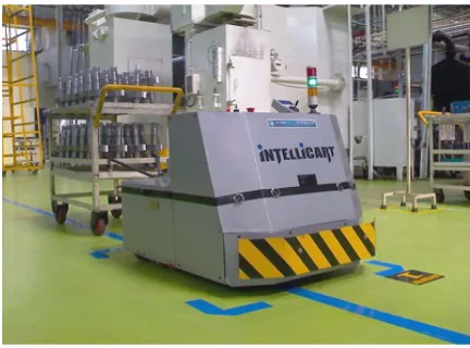
The inventions of Automated Guided Vehicle (AGV) have been around since the 1950’s and the first technology was constructed by Barret Electronics from Grand Rapids, Michigan. Then followed by the Europeans in the 1970’s and nowadays AGV can be found everywhere. One of the first AGV was a towing vehicle that pulled a series of trailers between two locations, and presently there are many functions in AGV can found and have a high potential to go far away in future. Several definitions of AGV have different understanding based on perspective respectively and one of them from The American Society of Safety Engineers (ASSE) that defines AGV as vehicles that are attached with sensing guided system (navigation devices) and can following prescribed paths and it is driverless system that are need to pre-programmed to function perfectly. Figure 1.0 shows the example of AGV applications at industrial environment.
AGV systems can be used mostly throughout the production process and offer many advantages compare to other types of handling systems, including:
a) Predictable, reliable, automatic operation b) Automated interfaces with other systems
c) Reduced handling damage through improved positioning d) Reduced operating and maintenance cost of material handling e) Efficient long-distance movements
f) Flexibility to changes in material handling requirements g) Creates an ergonomic, safe environment
h) Easily expandable layout and system capacity for maximum flexibility
[image:18.595.220.436.455.615.2]Considering the potentials and advantages of the Automated Guided Vehicle (AGV) in everywhere especially in workplace, it is valuable to do this research, as it also will be the first step towards the inventions of more intelligent technology or system. Develop a mobile robot involves the combination of different rules that includes kinematics, signal analysis, information theory, artificial intelligent and probability theory.
Figure 1.0: Automated Guide Vehicle (AGV) towing trolley. (Designed by: Hi-Tech Robotic
Systemz Ltd, India).
(Source: http://genericembedded.com/ge/robotics/agv-automated-guided-vehicle/)
1.2 Problem Statement
This AGV is designed to towing 300 kg trolley for Johnson Control Automotive Company at Alor Gajah. Previously, the trolley is used to carry part body of car by fully manual control using manpower. For that reason, the AGV system is used to improvise conventional system into fully automatic to enhance the productivity. Basically, a drive mechanism of the AGV consists of a drive unit to make movement and a steering unit to control movement of robot. An addition, several factors need to be taken into account in producing a good drive mechanism such as trolley weight, stability, motion planning, and structure design, which mostly will be influence the function of AGV itself. For example, excess load weight on trolley towed by a level capable of causing "slip" condition on the AGV, meaning that the tires turn but could not move in accordance with the instructions given. In other situations, the AGV will be lifted when an imbalance occurs between the AGV and the burden incurred. Knowing the right torque values in the motor used is very important so that the burden of affordable able towed by AGV. In this research included identify the factors involved, analyze the data obtained and improve the drives system for AGV that must be implemented.
1.3 Project Aim
The purpose of this project is a study about AGV drive mechanism and based on all the data and knowledge gained, trying to develop a system suitable and best for an AGV itself. The overall system includes how to solve the problem, generate the idea related with project and improvement method to make the best AGV ever. 1.4 Objective
The objective of this project that needs to be achieved is to evaluate as regards the drives mechanism of Automated Guided Vehicle (AGV) applications in manufacturing environments.
1.5 Project Scope
In building a good mobile robot or AGV, a few things need to be complied with and have a strong knowledge of the fundamentals of mobile robot consisting of locomotion, sensing, localization and motion planning. In order to attain the project objective, the following scopes are identified and determined:
a) Review AGV drive mechanisms include aspects of research through reliable sources, collect data, make comparisons, analyze the data in a suitable manner and further improvements are needed to produce the best AGV and work according to the instructions given.
b) Build a mobile robot at a small-scale prototype to be used as the experimental part in which the concept is used in the AGV is similar to other mobile robots such as Line Following robot. In this study, a total of 3 drive systems developed as front drive systems, rear drive systems, and center drive system. The purpose of each experiment is to see the differences and the resulting impact on the mobile robot during the experiment.
c) Identify the factor that influence AGV drives mechanism and based on that, prove it with data collected and simulated by using proper software to support the research.
d) The comparison among actual testing data that collected and result from simulation process by using software are implemented to determine the best solution in develop the AGV where that follow the desired criteria and functioning smoothly.
CHAPTER 2
LITERATURE REVIEW
Whole of this study focuses on the technology of mobility especially to drive mechanism of AGV: How can a mobile robot make a movement without supervision through real-world environments to fulfill its work? The challenge is about that locomotion itself and related with maneuverability it. What is it about a particular locomotion mechanism that makes it the best to become alternative locomotion mechanisms? The human can implements localization and cognition activities, but depends on the robot’s control scheme itself to provide motion control. Designing a mobile robot such as AGV involves the integration of different disciplines that includes software and hardware design considerations, related technologies, algorithmic techniques, kinematics, signal analysis, information theory, artificial intelligence and probability theory.
2.1 Mobile Robot Locomotion
Locomotion is about mechanism that used to move such as wheel, track and leg. It also known as physical interaction between vehicle and environment where should be consider terrain, control and mechanical complexity. According to Siegwart and Nourbakhsh (2004), had describes there are varieties of possible ways to move, and the selection of a robot’s locomotion is an important aspect of mobile robot design. Regarding locomotion rules, the environment is constant and the robot moves by deliver force to the environment. Based on the scientific basis, the study of
actuators that generate interaction forces among each other, and mechanisms that implemented require kinematic and dynamic properties. Both of them thus share the same basic attribute in terms of stability, contact characteristics, and environmental type:
a) Stability criteria included number and geometry of contact points, centre of gravity (COG), static/dynamic stability, and inclination of terrain.
b) Characteristics of contact are divides into three main part, contact point/path size and shape, angle of contact, and friction.
c) Type of environments included structure and medium (e.g. water, air, soft or hard ground). (Siegwart and Nourbakhsh, 2004).
2.1.1 Mobile Robot Legged (walking machines)
Legged locomotion is characterized by series of point contacts between the robot and the ground. Legged robot locomotion mechanisms are often inspired by biological systems, which are very successful in moving through a wide area of harsh environments. A legged robot is well suited for rough terrain; it is able to climb steps, to cross gaps which are as large as its stride and to walk on extremely rough terrain where, due to ground irregularities, the use of wheels would not be feasible. At least three legs are required to achieve stability in walking machine concept. It is becomes unstable with fewer legs and due the situation where some legs are lifted during walking. For static walking, it requires at least six legs in stability condition. See table 2.0, shown examples of walking machine in the market currently.
Table 2.0: Types of walking machine
Pictures Name Types
Toyota’s one legged robot Uniped
Honda Asimo Biped
WowWee Robotics Tripod or three legged robot
Sony Aibo Quadruped
Pentapod Robot Five legged robot
Hexapod Six legged robot
(Source: Mobile Robot Locomotion & Positioning System, Dr. Alaa Khamis, SMIEEE, 2012.)
2.1.1.1 Leg configuration
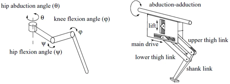
[image:24.595.116.518.241.388.2]To move a leg forward at least two degrees of freedom are required, one for lifting and one for swinging. Most legs have three degrees of freedom; this makes the robot able to travel in rougher terrain and to do more complex manoeuvres. Figure 2.0 shown attribute the leg that has three degrees of freedom. In general, adding degrees of freedom to a robots leg means increasing the manoeuvrability of the robot, the range of terrain on which it can travel and the ability to travel in a variety of gaits.
Figure 2.0: Two examples of legs with three degrees of freedom. (Siegwart and Nourbakhsh, 2004).
If the robot has more than one leg there is the issue of leg coordination for locomotion. The total number of possible gaits in which a robot can travel depends on the number on legs it has. The gait is a periodic sequence of lift and release events for each leg. The number of possible events N for walking machine with k legs and in explained in equation below.
Table 2.1: Advantages and disadvantages of walking machine
Advantages
i. Adaptability and maneuverability in rough terrain. Because only a set of point contacts is required, the quality of the ground between those points does not matter so long as the robot can maintain adequate ground clearance.
ii. The potential to manipulate objects in the environment with great skill. An excellent insect example, the dung beetle, is capable of rolling a ball while locomotion by way of its dexterous front legs.