This is a repository copy of
Piezoelectric sensors to monitor lubricant film thickness at
piston-cylinder contacts in a fired engine
.
White Rose Research Online URL for this paper:
http://eprints.whiterose.ac.uk/94623/
Version: Accepted Version
Article:
Mills, R.S., Avan, E.Y. and Dwyer-Joyce, R.S. (2013) Piezoelectric sensors to monitor
lubricant film thickness at piston-cylinder contacts in a fired engine. Proceedings of the
Institution of Mechanical Engineers, Part J: Journal of Engineering Tribology , 227 (2). pp.
100-111. ISSN 1350-6501
https://doi.org/10.1177/1350650112464833
eprints@whiterose.ac.uk https://eprints.whiterose.ac.uk/
Reuse
Unless indicated otherwise, fulltext items are protected by copyright with all rights reserved. The copyright exception in section 29 of the Copyright, Designs and Patents Act 1988 allows the making of a single copy solely for the purpose of non-commercial research or private study within the limits of fair dealing. The publisher or other rights-holder may allow further reproduction and re-use of this version - refer to the White Rose Research Online record for this item. Where records identify the publisher as the copyright holder, users can verify any specific terms of use on the publisher’s website.
Takedown
If you consider content in White Rose Research Online to be in breach of UK law, please notify us by
Piezo-electric sensors to monitor lubricant film thickness at
piston-cylinder contacts in a fired engine
R. S. Mills
1,2, E. Y. Avan
1, R. S. Dwyer-Joyce
11The Leonardo Centre for Tribilogy
The University of Sheffield Mechanical Engineering Department
Mappin Street, Sheffield, S1 3JD, UK 2Corrispondance author, email:robin.mills@shef.ac.uk
May 2012
Abstract
The contact between the piston ring and cylinder liner is the most important sealing interface in an automotive engine. Understanding the contact interactions and lubricant film formation at this interface is crucial for the development fuel efficient and low emission engines. This paper outlines the development of an ultrasonic approach to enable non-invasive measurement of the lubricant film thickness formed between piston and cylinder wall of a fired engine.
The sensor system consisted of a series of small, low cost piezoelectric elements which were bonded to the external surface of a four-stroke, single cylinder engine. Each element could be individually energised with a short duration voltage pulse and reflections from the cylinder inner bore recorded. By using high frequency pulsing and data capture it proved possible to image individual ring and skirt contacts at full engine speeds. These captured reflections were processed to give lubricant film thickness directly and without the need for independent calibration. The results show high repeatability between cycle sets at specific running conditions. The lubricant films at each of the ring contacts can be measured at sufficient resolution such that individual rails of the oil control ring can be monitored. In addition, the film generated at the skirt was measured, the results from which, suggest the occurrence of ’piston slap’ and highlight the potential for this ultrasonic method to enable indirect measurements of piston secondary dynamics.
Introduction
The interfaces between the piston and cylinder are ar-guably the most complex in an internal combustion engine. The capability of these contacts to provide optimal seal-ing and thrust support whilst minimisseal-ing frictional losses and lubricant consumption directly affects parasitic en-ergy loss and associated emissions. As computational ca-pabilities increase, there is a strong desire for much of the development of the piston assembly to be carried out using software, but the complex dynamics and transient nature of an engine requires robust empirical data be available to
provide validation for such codes.
based [20]. Each of these techniques has had varying de-grees of success [16], however all are invasive, requiring penetration of the cylinder wall and significant modifica-tion of the cylinder and for this reason tend not to be used outside of the laboratory.
This paper outlines the application of an ultrasonic method [6] to measure lubricant film formation between the piston assembly and cylinder wall of a fired engine. The approach is based on transmitting discrete ultrasonic pulses through the cylinder wall using externally mounted sensors and recording reflections from the lubricated con-tact as the piston passes. It has thus proved possible to monitor the lubricant film, without requiring cylinder pen-etration and with minimal modification to the external surface of the cylinder. The method is fully capable of running externally to a test cell environment and has the potential to be used during the ’field test’ of a production vehicle. The use of ultrasound for measurement of tribo-logical films has been successfully applied to cases both in laboratory conditions [6], [8], [21] and machine elements [2], [14] and highlights the versatility of the the technique.
Measurement system and
method-ology
The Engine Unit
[image:3.595.306.531.79.440.2]The engine used during this work was a 5hp, single cylin-der, four-stroke Briggs and Stratton Quantum unit. The benefits of this engine included its small size and portabil-ity as well as its air-cooled design, enabling simple sensor application to the external surface of the cylinder. The engine was mounted on a wheeled platform and operated outside the lab, highlighting the freedom of the technique from the constraints of a test cell (see figure 1a and table 1).
Table 1: Briggs and StrattonQuantum engine information
No. Cylinders 1
Capacity 190cc
Stroke 52mm
Bore 68mm
Compression Ring Width 1.54mm
Fuel Mixing Carburetor
(a)
(b)
Figure 1: (a) Photograph of engine unit and acquisition apparatus, (b) Schematic showing engine instrumentation
Mechanical Instrumentation
A simple loading mechanism consisting of a hydraulic disc brake coupled through a load cell was constructed. A ro-tary encoder was mounted to the end of the crank shaft to provide shaft speed. This system was able to function as a rudimentary dynamometer, applying a measurable resis-tive torque as well as recording engine speed thus giving an approximate measure of developed shaft power (see figure 1b).
The Sensor Array
Figure 2: Engine section depicting contacts being investigated
(see figure 2) however this was the only structural modifi-cation that had to be performed.
Principally, the technique uses a piezoelectric element bonded to the exterior surface of the contact to gener-ate an ultrasonic pulse when excited with a short dura-tion voltage signal. This sound wave propagates through to the interface where some of the energy is lost through the contact before being reflected back to the element. This energy loss depends partly on the thickness of the fluid film, changing the condition of the reflection and it is this effect that is exploited in these measurements. The particular piezoelectric transducer configuration used in this work is often referred to as the ’pulse-echo’ method, whereby the same transducer acts as the emitter (send-ing the pulse) and receiver (sens(send-ing the reflection). The transducers used for this system were made from low cost, off the shelf 10MHz piezoelectric discs formed from high sensitivity Lead Zirconate Titanate (PZT). The nominal diameter and thickness of the piezo-elements was 7.1mm and 0.2mm respectively and came pre-sputtered with wrap around electrodes of silver. The spatial resolution of the measurements depends partially on the geometry of the sensors. If used in the disc form, the sensing area would have been approximately 5 times that of the thickness of the ring. As a consequence, the disc elements were mod-ified to form strips, 7.1mm long and 1.5mm wide, com-parable to the width of the compression ring, providing a much narrower sensing area.
To obtain measurements at a series of locations down the axis of the cylinder, an array of 7 sensors was bonded to the modified region of the cylinder; shown in figure 3, using a high temperature adhesive (Vishay M-bond 610). Unfortunately, due to the arrangement of the head clamp-ing bolts, it was not possible to place a sensor at the TDC position of the compression ring where the minimum film might be expected.
Figure 3: schematic showing (a) sensor position on bore, (b) ring position on piston and (c), photo of sensor array
The Acquisition Equipment
[image:4.595.313.558.242.488.2]Figure 4: Schematic overview of system
Ultrasonic Signal Generation and
Acquisi-tion
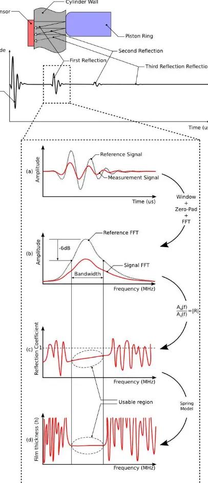
To recap, the ultrasonic wave generated by the PZT ele-ments propagates towards the internal surface of the bore at which point a portion of the wave is reflected back to the transducer. The amplitude and frequency content of the reflected portion of the signal, in part, is governed by the conditions of the contact. However this ultrasonic wave will undergo a series of additional reflections as it bounces between the internal and external cylinder sur-face (shown schematically in figure 5) and the PZT ele-ment will sense these multiple ’echoes’. While the wave propagates, energy is lost through three main main mech-anisms; the degree of acoustic coupling at the interface surfaces (governed by the conditions of the oil film), the geometric dispersion of the wave and attenuation within the carrying media (in this case the cylinder wall). As a consequence the first reflection was captured (correspond-ing to the cylinder-r(correspond-ing contact) to maximise the signal-to-noise ratio, being extracted from the rest of the signal using a simple rectangular window. This method had the additional benefit of reducing the rate of data being stored enabling the pulse rate to be maximised (see figure 5).
Figure 5: Signal processing sequence showing a schematic of the A-scan produced from an interface. (a) Time domain signal for an air interface (reference) and oil film, (b) Time signals transformed into the fre-quency domain, (c) Reflection coefficient obtained by the division of film FFT by reference FFT.
Analysis Procedure
[image:5.595.44.335.68.210.2]consid-ered a total internal reflection of the sound wave as ap-proximately 99.99% of the incident acoustic energy is re-flected under such conditions. By generating local refer-ences for each engine cycle, any drift in sensor response (due to temperature changes etc.) could be removed.
Mathematically processing the data to obtain oil film thickness is now well documented in many articles, [7], [5] and is explained only briefly here. This ultrasonic tech-nique is inherently based on physical principles of the sys-tem meaning that a calibration as such is not required. Instead, experiments to determine the validity of the pro-cess steps have been carried out [21]. Excellent agreement was documented for the quasi-static spring model tech-nique.
Initially, the reflected signals (reference and measurement) are processed using the fast Fourier transform and a frequency-wise division is performed to give a frequency dependent reflection coefficient. The frequency range within the -6dB bandwidth of the sensor was then pro-cessed using the quasi-static spring model proposed in [12] with the mean film calculated from the frequencies con-tained within the specified bandwidth. As an overview, the reflection coefficient|R|(ω) can be related to the stiff-ness of the lubricant layer by equation 1.
R=(z1−z2) +iω(z1z2)/K (z1+z2) +iω(z1z2)/K
(1)
z1 and z2 are the acoustic impedance values of the
cylin-der wall and piston component, formed from the the prod-uct of the speed of sound, c and the density, ρ. ω is the specific angular frequency of the ultrasound under consid-eration (within the bandwidth of the sensor). To obtain the acoustic properties of the cylinder and piston compo-nents, a small piece of the cylinder (removed from part of a cooling fin) and the compression ring were analysed. The density of each was found and speed of sound mea-sured using the ’time of flight’ method, whereby the time required for an ultrasonic wave to pass through a section of known thickness was recorded. The product of these two quantities give the materials’ acoustic impedance and are given in table 2.
The stiffness, K, can be related to the properties of the lubricant layer by equation 2.
K= B
h (2)
WhereBis the bulk modulus of the lubricant andhis the thickness of the lubricant layer. Measuring bulk modulus poses a challenge, however it can be related to the speed of sound and density of the fluid as in equation 3.
K=ρc
2
h (3)
The bulk modulus of oil (and correspondingly speed of sound) is highly dependant on temperature. To charac-terise the oil, the same ’time of flight’ principle was em-ployed by passing a pulse through a channel of oil with a known separating gap at different temperatures (22 to 100◦C) and characterised by linear regression, the fit of which is given in table 2. It is prudent to highlight that the bulk modulus is also dependant upon pressure, but poses a more significant challenge to measure, particu-larly in the contact. For the content of this paper, the properties of the fluid within the contacts was assumed to be equivalent to those at ambient pressure. Various com-putational simulations have been performed to estimate maximum hydrodynamic pressures within the ring-liner contact, with results ranging from 8MPa to 50MPa [1], [13]. If such higher pressures are assumed to exist (prob-ably unlikely in engine used within this work and even if so, only over a very localised region of the ring), equa-tion 3 suggests that the film may be under-measured as an increased bulk modulus for a constant film thickness will increase the propensity for the ultrasound pulse to be transmitted through the contact and will lower the ob-served reflection coefficient. An error of the order of 10-15% in film measurement (estimated from data within [6]) could be possible, given such film pressures. This clearly highlights implications of the assumption the validity of which is the subject of current work.
By combining and rearranging equations 1 and 3, the oil film thickness as a function of reflection coefficient is given by 4.
h= ρc
2
ωz1z2
s
|R|2(z
1+z2)2−(z1−z2)2
1− |R|2 (4)
Table 2: Engine structure and lubricant acoustic proper-ties Engine components Acoustic impedance (MRayl) Bulk modulus (GPa) Aluminium Cylinder and Piston 17.3 76 Cast Iron
Piston Ring 34.7 169
Lubricant Density (Kg/m3
Speed of sound (m/s) 15W40
motor oil 890
c=
−3.238T+1519
at any given measurement. For situations where the film at the piston skirt was being measured, resulting in an aluminium-oil-aluminium system, equation 4 could be simplified to equation 5 as z1 andz2were equal.
h= 2ρc
2
ωz
s
|R|2
1− |R|2 (5)
Cycle sequence analysis
Under the described set up it was not possible to obtain an absolute measure of crank angle for each ultrasonic pulse, but there were sufficient differences in signal structure over the four strokes to identify individual cycles. To separate and extract cycle sets from the film data, an algorithm was written to take a ’master’ cycle; identified by the user, and cross-correlate it with the entire data set to identify similar matching sub-sequences. To overcome the lack of absolute crank position and locally varying speed of the engine, the ’master’ sequence was stretched and cross correlated itera-tively to respond more robustly to locally faster and slower cycles (resulting from the fluctuating engine speed). The array of identified cycle sets was then analysed to extract the average minimum oil film thickness (MOFT) at the dif-ferent sensor positions for the compression ring and skirt. During this process, the appropriate material boundary conditions were applied according to the piston position and the local temperature of the oil was accounted for.
Results and Discussion
A set of test runs were performed involving idle and loaded conditions. The throttle of the engine was set manually, but the shaft speed was metered by an inertial governor and meant that specific load/speed combinations could not be set.
Visualisation of oil film
The engine throttle was set to approximately 90 percent of its range and allowed to stabilise for a short period. A load was applied to the brake disc and manually con-trolled to maintain a torque of 7Nm however, due to brake heating and subsequent fluid expansion, fluctuations of
±1Nm were observed. This loading produced a mean en-gine speed of 2,230 rpm corresponding to a measured shaft power of approximately 1.6kW. Data was captured over a period of 5 seconds for each sensor and contained approx-imately 90 full engine power strokes.
Figure 6 shows shows the measured film from a set of four full cycles of the engine at sensor position 6, with each of the data sets plotted in a different colour. Of note is the
degree of repeatability between the cycle sets, particularly at each of the rings. The lower portion of figure 6 shows how the measurements relate to the movement of the pis-ton with the highlighted line passing through sensor 6 on the barrel.
Figure 7 focuses on the expansion stroke. Each of the rings is well defined including the twin rails of the oil scraper ring despite each rail having a width of 0.8mm. The lands of the piston were not visible as the diameter was ap-proximately 500 microns smaller than the bore (at room temperature), meaning that the thickness of the oil film would have been outside the functional range of the spring model. It should be noted that the measured profile of the ring observed in the film thickness data does not directly correspond to the true geometric shape of the ring. The observed curvature is the result of the ring passing the observation window of the sensor which is 2/3 the width of the compression ring. In the current form, it is only the minimum point of the dip that provides a meaning-ful measure of film thickness as away from this point, the processed data applies to a partial overlap of the ring and observation window, appearing as a thicker film.
Film thickness at the compression ring
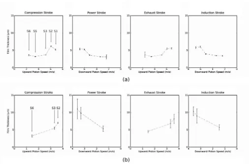
MOFT data has been plotted in figure 8 and for clarity, the individual strokes of the cycle have been isolated with each data point formed from the mean of a series of cy-cle sets. The standard deviation is plotted to indicate the degree of variation between cycle sets. The local piston speed has been inferred from the local rotational speed of the engine, relative position of the sensor and geometry of the piston.
During loaded conditions (figure 8a), all strokes show that the MOFT increases with piston speed typically from 3.2 microns at 2.2m/s to 5.8 microns at 7m/s. This suggests that a hydrodynamic wedge is forming at the interface, increasing surface separation with increasing lubricant en-trainment speed. The data shows good consistency tween cycle sets, with the standard deviation generally be-ing below 0.3 microns, though some fluctuation occurred at BDC following the combustion stroke. Little variation between strokes suggests that the compression ring is not supporting a greatly varying load from combustion pres-sure. Comparing measurements with work by other au-thors ([17], [18]) gives measurements of similar magnitude erring on the lower side, however it should be noted that the work in both these papers was performed using large diesel engines rather than a small, single cylinder gasoline unit.
oper-Figure 6: Superimposed oil film traces from sensor 6 as the piston moves through the four strokes of a cycle, with passage of the piston highlighted
ation that the engine would ’hunt’ erratically during idle conditions due to the feedback from the speed dependent throttle governor. Only measurements from sensors 2, 3 and 6 only are plotted as those from 4 and 5 were trou-blesome to pin-point. Future simultaneous measurements of ultrasonic data with crank position would provide a means of geometrically isolating the position at which the compression ring should be visible.
Film thickness at the skirt
By the nature of the experimental set up, the crank po-sition during each sensor’s measurement period was dif-ferent for each of the rings and the skirt. Consequently,
the speed of the piston at each measurement position was different for the skirt and compression ring (as shown in figure 9). In addition to this, the relative length of the skirt meant that it was ’visible’ to the sensor over a large portion of the stroke during which time there would have been a significant change in piston speed. Consequently the MOFT data has been plotted against the mean speed of the skirt within the measurement region, given the ro-tational speed of the engine.
[image:8.595.97.507.53.507.2]Figure 7: Plot showing expansion stroke from sensor 6
7 and 22.5 microns (at the very extremity of the thickness that can be measured). This result correlates reasonably well with the findings documented in [11] where canting of the piston during the power stroke was observed. The pumping strokes suggest that the film is thicker when the piston is slower, an effect that may be the result of sec-ondary motions of the piston which is also suggested by the large variance at each data point. The compression stroke shows an interesting arched MOFT which may be the result of the pressure building within the cylinder, af-fecting the local orientation of the piston, though further investigation is warranted to substantiate this hypothesis.
Evaluation of the applicability of the
ultra-sonic technique
The findings contained within this paper suggest that the ultrasonic technique has the potential to provide a min-imally invasive route to obtain oil film thickness infor-mation at the piston-cylinder interface. However the au-thors think it prudent to outline current limitations of the method.
• The bulk modulus of the oil: A key assumption, eluded to previously in the text, is that the pres-sures within the contact are low enough not to have an effect on the bulk modulus of the oil. Simulations of ring-cylinder contacts however, suggest this may not be the case and so the validity of this assump-tion is the focus of ongoing research. In addiassump-tion to the effect of pressure, the presence of contaminants (such as soot) and dissolved air is of interest.
• Spatial resolution of sensors: The size of the sen-sor in relation to the contact will limit the ability to resolve the true minimum film, particularly at
the ring contact. This issue is also present in other techniques, however improvements are being made miniaturise the sensors and improve signal process-ing techniques.
• Data acquisition: The equipment used in this test limits the acquisition rate to between 80K and 100K measurements per second which is lower than that of other techniques such as capacitative measurements where 200K measurements per second are being ac-quired [17]. Hardware improvements are always be-ing made and would have the potential to increase this limit thus improving resolution particularly at higher engine speeds. However a physical limit (with the current methodology) will exist due to the finite speed of sound of the cylinder material, whereby the echo sequence from a pulse will not have decayed suf-ficiently before a subsequent pulse is initiated, how-ever this limit is unlikely to be a problem for the speed range of most engines.
• Sensor robustness: This set of experiments has shown that the piezoelectric elements can operate at elevated temperatures, having been placed on the exterior surface of an air-cooled engine and subjected to temperatures in excess of 100◦C.
Conclusions
Figure 8: Mean film thickness occuring at compression ring during (a) loaded conditions, (b) idle conditions
1. A highly flexible system has been constructed to monitor MOFT within the piston-cylinder contact during combustion with minimal modification to the base engine. The approach has demonstrated the ability to operate without the constraints of dedi-cated test cell conditions and highlights the potential for installation within road going vehicles.
2. The intermittent nature of the signal observed at each sensor enable compensation routines to be ap-plied, ensuring any response drift due to thermal effects or otherwise can be accurately removed on a cycle to cycle basis.
3. It has been shown that the rings and skirt can be imaged with a high degree of clarity.
4. The high capture rate of the sensors has shown an interesting oscillation at the skirt of the piston dur-ing the expansion stroke. This may be the result of ’piston-slap’ though more work is required to verify this idea.
5. Results show that MOFT can be measured at the ring-pack and skirt with low data variance when the piston is loaded. An increase in MOFT with speed was observed at the compression ring (though little difference between strokes) varying between
3.2 and 5.8 microns during loaded conditions. The skirt MOFT was much smaller during the expan-sion stroke ( 4 to 7 microns) though during pump-ing strokes the film reduced with increaspump-ing speed. The large variance in data however, suggests that secondary piston motions may be the cause.
Acknowledgements
The work carried out in this paper has been financed in part by the Encyclopaedic consortium set up by the EP-SRC. The authors would like to express their gratitude to the funding agency and to the academic and industrial partners in the consortium for help and support.
References
[1] O. Akalin and G.M. Newaz. Piston ring-cylinder bore friction modeling in mixed lubrication regime: part i -analytical results. Journal of tribology, 123:211, 2001.
Figure 9: Mean film thickness occuring at skirt during loaded conditions
of clearance on friction, lubrication and squeaking in large diameter metal-on-metal hip replacements. Journal of Materials Science: Materials in Medicine, 19(4):1575–1579, 2008.
[3] JS Courtney-Pratt and GK Tudor. An analysis of the lubrication between the piston rings and cylinder wall of a running engine. ARCHIVE: Proceedings of the Institution of Mechanical Engineers 1847-1982 (vols 1-196), 155(1946):293–299, 1946.
[4] TA Dow, CA Schiele, and RD Stockwell. Technique for experimental evaluation of piston ring-cylinder film thickness. Journal of lubrication technology, 105(3):353–360, 1983.
[5] RS Dwyer-Joyce. The application of ultrasonic NDT techniques in tribology.Proceedings of the Institution of Mechanical Engineers, Part J: Journal of Engi-neering Tribology, 219(5):347–366, 2005.
[6] RS Dwyer-Joyce, BW Drinkwater, and CJ Donohoe. The measurement of lubricant-film thickness using ul-trasound. Proceedings of the Royal Society of Lon-don. Series A: Mathematical, Physical and Engineer-ing Sciences, 459(2032):957, 2003.
[7] R.S. Dwyer-Joyce, D. Green, S. Balakrishnan, P. Harper, R. Lewis, P. King, and H. Rahnejat. The measurement of liner-piston skirt oil film thickness by an ultrasonic means. 2006.
[8] RS Dwyer-Joyce, P. Harper, and BW Drinkwater. A method for the measurement of hydrodynamic oil films using ultrasonic reflection. Tribology Letters, 17(2):337–348, 2004.
[9] S. Furuhama and T. Sumi. A dynamic theory of piston-ring lubrication: 3rd report, measurement of oil film thickness. Bulletin of JSME, 4(16):744–752, 1961.
[10] GM Hamilton and SL Moore. Comparison between measured and calculated thicknesses of the oil-film lu-bricating piston rings. ARCHIVE: Proceedings of the
Institution of Mechanical Engineers 1847-1982 (vols 1-196), 188(1974):262–268, 1974.
[11] M. Kamiya, T. Kobayashi, Y. Mihara, and T. Someya. Measurement of Piston Skirt Oil-film Pressure under Piston Slap. 2007.
[12] J. Krautkramer and H. Krautkramer. Ultrasonic test-ing of materials. Springer- Verlag New York, Inc. 1977, 667 p(Book)., 1977.
[13] M. Priest, D. Dowson, and CM Taylor. Theoret-ical modelling of cavitation in piston ring lubrica-tion.Proceedings of the Institution of Mechanical En-gineers, Part C: Journal of Mechanical Engineering Science, 214(3):435–447, 2000.
[14] T. Reddyhoff, R. Dwyer-Joyce, and P. Harper. Ul-trasonic measurement of film thickness in mechanical seals. Sealing Technology, 2006(7):7–11, 2006.
[15] T. Seki, K. Nakayama, T. Yamada, A. Yoshida, and M. Takiguchi. A study on variation in oil film thick-ness of a piston ring package: variation of oil film thickness in piston sliding direction. JSAE Review, 21(3):315–320, 2000.
[16] I. Sherrington and EH Smith. Experimental meth-ods for measuring the oil-film thickness between the piston-rings and cylinder-wall of internal combustion engines.Tribology international, 18(6):315–320, 1985.
[17] S.J. S¨ochting and I. Sherrington. The effect of load and viscosity on the minimum operating oil film thickness of piston-rings in internal combustion en-gines. Proceedings of the Institution of Mechanical Engineers, Part J: Journal of Engineering Tribology, 223(3):383, 2009.
[19] LL Ting. Development of a laser fluorescence tech-nique for measuring piston ring oil film thickness. J. Lubr. Technol, 102:165–171, 1980.
[20] RD Wing and O. Saunders. Oil film temperature and thickness measurements on the piston rings of a diesel engine. ARCHIVE: Proceedings of the
Institu-tion of Mechanical Engineers 1847-1982 (vols 1-196), 186(1972):1–9, 1972.