This is a repository copy of A comparison of wear behaviour of heat resistant steel engine valves and TiAl engine valves.
White Rose Research Online URL for this paper: http://eprints.whiterose.ac.uk/149307/
Version: Accepted Version Article:
Lai, F., Qu, S., Qin, H. et al. (4 more authors) (2019) A comparison of wear behaviour of heat resistant steel engine valves and TiAl engine valves. Proceedings of the Institution of Mechanical Engineers Part J: Journal of Engineering Tribology. ISSN 1350-6501
https://doi.org/10.1177/1350650119872093
Lai, F., Qu, S., Qin, H. et al. (Accepted: 2019) A comparison of wear behaviour of heat resistant steel engine valves and TiAl engine valves. Proceedings of the Institution of Mechanical Engineers Part J: Journal of Engineering Tribology. SAGE Publications, ISSN 1350-6501.
[email protected] https://eprints.whiterose.ac.uk/
Reuse
Items deposited in White Rose Research Online are protected by copyright, with all rights reserved unless indicated otherwise. They may be downloaded and/or printed for private study, or other acts as permitted by national copyright laws. The publisher or other rights holders may allow further reproduction and re-use of the full text version. This is indicated by the licence information on the White Rose Research Online record for the item.
Takedown
If you consider content in White Rose Research Online to be in breach of UK law, please notify us by
1 / 30
A comparison of wear behaviour of heat resistant steel engine valves
and TiAl engine valves
Fuqiang Lai1,2, Shengguan Qu1*, Haidi Qin1, Roger Lewis2, Tom Slatter2, Xiaoqiang Li1, Huahuan Luo3
1. Guangdong Key Laboratory for Advanced Metallic Materials Processing, School of Mechanical and Automotive
Engineering, South China University of Technology, Guangzhou 510640, Guangdong, China
2. Department of Mechanical Engineering, The University of Sheffield, Mappin Street, Sheffield, UK, S1 3JD
3Huaiji Dengyun Auto-parts (Holding) CO., LTD. Huaiji County 526400, Guangdong, China
Abstract:
The increasingly demand for higher performance internal combustion engines (ICEs) has led to
higher temperatures in the combustion chamber. As a result, TiAl valves have been investigated
with a view to their use in a natural gas fuelled diesel ICE, taking advantage of their low density
and good high temperature resistance. In this work, comparison bench tests for traditional steel
valves and TiAl valves were carried out through the use of specially designed wear testing
apparatus. Compared to the traditional valves made from heat resistant steel (X60, X85), the
TiAl valves have 50 % lower mass, leading to a decrease in the impact seating forces during the
engine operation. With the reduction of the inertia of engine valve movement, the dynamic
characteristics of the engine valve train system can be optimized. Each contact pair of valve and
seat insert was tested for 3 million impact cycles. Compared to the austenitic exhaust valves
(X60) tested at 700 °C, the TiAl valve had better wear resistance and the wear loss decreased by
24.8 %. The predominant wear mechanism is considered to be a combination of oxidative wear
2 / 30
and adhesive wear. However, for the intake valves tested at 400 °C, the wear loss of the TiAl
valve was three times higher than the martensitic intake valves (X85). The predominant wear
mechanism can be identified as abrasive wear and adhesive wear. It is therefore concluded that
the TiAl exhaust valve is a potential solution for a natural gas fuelled diesel.
Key words: engine valve; TiAl alloy; wear test; wear behaviour
1. Introduction
The valve and valve seat insert are critical components of the valve train, which is in turn the
most important system in an internal combustion engine (ICE), as it controls the gas flow and
the timing of the engine [1, 2]. One of the main design objectives for an ICE is an increase in the
specific power output, however, this often leadsto higher combustion chamber temperatures that
cause premature failure of exhaust valves, in particular.Meanwhile, lightweight design is one of
the most important development trends of the engine industry, due to the increasingly high
requirements of fuel efficiency and strict emission regulations. Many new materials and designs
have been developed for engine valves. However, it was difficult to obtain substantial weight
reductions through the use of traditional heat resistant steel or nickel-base or cobalt-base super
alloys. Thus, TiAl alloy is becoming a potential material with its low density and excellent
mechanical properties at elevated temperatures, albeit with higher raw material and
manufacturing costs [3]. TiAl alloys are considered as important candidate materials for
advanced applications in aerospace, as well as the automotive industry [4, 5].
Engine valves are the products of mass-production with high precision. The valves made from
traditional heat resistant steel are generally manufactured by hot forming and machining.
3 / 30
TiAl valves by hot forming. Research has already been carried out, however, to produce a TiAl
valve with low cost and high production efficiency through different manufacturing methods [5,
6]. Other work has reported that centrifugal casting combined with a mechanical machining
process was found to be a viable method [7–9]. Furthermore, the TiAl valves can be also
manufactured by powder metallergy technology [10].
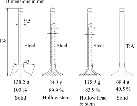
Fig. 1 Mass comparison of valves with different materials and configurations.
Fig. 1 presents the masses of valves typically used in a medium duty natural gas fuelled engine
with different materials and configurations. The solid exhaust valve made of heat resistant steel
is being used in a natural gas fuelled engine. The hollow stem and sodium filled valve and
hollow head and sodium filled valve were manufactured and developed by Huaiji Dengyun
Auto-parts (Holding) CO., LTD [11, 12]. The mass of a hollow valve is 83.9 %. of the mass of
the solid valve. However, the mass of a TiAl valve would be further decreased to 49.5 %. The
mass of the valves is a small proportion of the total mass of an ICE, but they occupy a large
proportion of the valve train system (moving) mass. With the reduction of valve mass, the
stiffness of valve spring can also be reduced, leading to a decrease in noise and impact seating
43 138
138.2 g 115.9 g
100 % 83.9 %
Solid Hollow stem Hollow head & stem
Solid
Steel Steel Steel TiAl
9.5
5 5
124.3 g
89.9 %
[image:4.595.175.442.220.426.2]4 / 30
forces [5]. Consequently, the severe contact conditions between valves and seat inserts could be
mitigated to some extent. A further benefit, due to the reduction of the inertia of the engine
valves, is that the dynamic characteristics of the valve train system could be significantly
improved (e.g. its ability to respond user demand), leading to increase in fuel economy.
Some research on TiAl engine valves has been carried out in a dynamometer engine test [5, 9,
10]. For instance, Maki et al. reported that the TiAl prototype valve demonstrated excellent
high-temperature performance and wear resistance under the very severe conditions of a
durability test on an actual fired engine [5]. Ouyang et al. performed 48 hour comparative tests
on a diesel engine [9]. It is also reported that the valve recession of TiAl exhaust engine valves
is 12.5 % of that for heat resistant steel engine valve (21-4N). However, it is reported by Li and
Luo [10], that the valve recession of TiAl exhaust valves was almost the same as the original
exhaust valve recession in a diesel. Unfortunately, the corresponding detailed wear behaviour
and wear mechanisms have yet to be presented and discussed in published literature.
Therefore, in the work presented in this paper, wear tests for heat resistant steel engine valves
and TiAl engine valves were carried out through the use of specially designed wear testing
apparatus. Stress analysis of the valve specimens during the durability tests was performed using
a finite element method (FEM), and the sliding distance was calculated. After the test, the wear
loss from the seating face of the valve and seat insert were quantified through use of a
profilometer. The worn seating faces were characterized using scanning electron microscopy
(SEM), energy–dispersive spectroscopy (EDS) and wear behaviour and wear mechanisms were
5 / 30
2. Experimental details
2.1 Materials
In modern engines, martensitic steels are generally used for the intake valves, and austenitic
alloys and super alloys are used for exhaust valves. In this work, martensitic steels of
85Cr18Mo2V (X85) and 45Cr9Si2 steel were used for the intake valves and the valve stem of
exhaust valves, respectively. Austenitic steel 61Cr21Mn10Mo1V1Nb1N (X60) was used for the
valve head of the exhaust valves. In addition, valve specimens with the same geometry of the
intake valve and exhaust valve were made of a TiAl alloy. The nominal chemical compositions
of the engine valve materials and seat inserts are presented in Table 1. The mechanical properties
of the X85 and X60 steel at high temperature were obtained using an ultimate tensile testing
machine, and the mechanical properties of TiAl alloy refer the work reported by Badami et al. [3]
and Maki et al. [5], as listed in Table 2. The Young's modulus of X60 at 700 °C was only 136
GPa, which was significantly lower than the Young's modulus of X85 at 400 °C (197 GPa). It
should be noted that TiAl alloy could obtain quite outstanding mechanical properties at the high
temperature [5]. Compared the temperature at 400 °C to the temperature at 700 °C, tensile
strength of TiAl alloy kept the similar values, its Young's modulus slightly decreased from 160
GPa to 151 GPa, and the hardness reduced from 280 HV to 270 HV. However, at the
temperature range lower than 700 °C, the elongation of TiAl was at low levels, indicating its low
formability. The hot hardness of the engine valve and seat insert materials are listed in Table 3. It
should be noted that the hardness at elevated temperatures refers to the results reported by Wang
[1] and Maki et al. [5].
6 / 30
were produced by traditional hot forming and a mechanical machining process, whereas the
TiAl valves were manufactured through centrifugal casting and mechanical machining process.
Compared to the heat resistant steel valve, the mass of TiAl valve decreased to be 50 % lighter.
In order to increase the wear resistance of the valve stem and the peening and wear resistance of
the valve head seating surface, surface treatments are generally introduced [1, 5]. For instance,
the valve stem of Valve 1 was made of 45Cr9Si3 steel, and the surface of valve stem was
enhanced by chromium plate. The valve seating face of Valve 1 was nitrided. The nitriding
process was performed by salt bath liquid nitriding at 580 °C for 35 to 40 minutes. Additionally,
the seating face of Valve 3 was quenched, leading to the hardness of surface varied from 48 to
56 HRC, and the depth of hardening was 0.5 to 2.0 mm with 390 HV. After the quenching
treatment, the hardness of the seating face of Valve 3 was significantly higher than the hardness
[image:7.595.19.582.454.665.2]of matrix material.
Table 1 The nominal compositions of the engine valve specimens and seat inserts (wt. %). C Si Mn Ni Cr Mo V Cu Fe Ti Others
X60 0.65 0.21 10.40 0.45 20.65 0.79 0.79 0.02 Bal. – N: 0.37; Nb: 1.06
45Cr9Si3 0.44 2.92 0.33 0.15 8.58 – – 0.15 Bal. – –
X85 0.81 0.31 0.47 – 18.1 2.26 0.39 0.13 Bal. – –
TiAl –
0.1
-0.2 – –
1.0
-1.3 – – – –
Bal.
Al: 30-34; Nb: 4.0-5.0;
W: 4.0-5.0
Seat insert 0.9 -1.1 0.3 -0.5 0.4 -0.5 1.2 -1.4 5.0 -5.3 12.0 -12.5 1.0 -1.2 13.0 -15.0
7 / 30
Table 2 Mechanical properties of engine valve materials [3, 5].
Temperature (°C) b (MPa) s (MPa) Young's modulus (GPa) Elongation (%)
X85 400 958 791 197 10.45
TiAl 400 570 – 160-165 ~ 3
TiAl 700 572 ~ 470 151 ~ 3.5
[image:8.595.49.546.321.440.2]X60 700 634 341 136 22.51
Table 3 Hot hardness of the engine valve and seat insert [1, 5].
25 °C 400 °C 500 °C 600 °C 700 °C
X85 320 HV0.2 – – – –
TiAl 305 HV (5kgf) 280 HV (5kgf) 275 HV (5kgf) 270 HV (5kgf) 270 HV (5kgf)
X60 403 HV0.2 ~ 350 HV ~ 250 HV ~ 160 HV –
Seat insert 462 HV0.2 > 300 HV – – –
Table 4 Details of the valve specimens.
Valve name Valve type Valve stem material Valve head material Valve seating face material Valve weight (g)
Valve 1 Exhaust valve 45Cr9Si3, chroming X60 X60, nitriding 153.6
Valve 2 Exhaust valve TiAl, polishing TiAl TiAl, polishing 76.5
Valve 3 Intake valve X85, chroming X85 X85, quenching 162.8
Valve 4 Intake valve TiAl, polishing TiAl TiAl, polishing 80.9
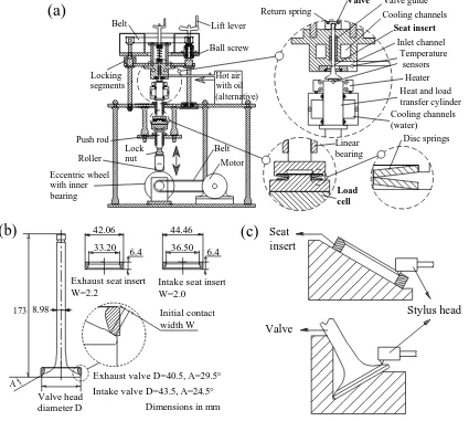
2.2 Wear apparatus and test conditions
[image:8.595.75.541.493.662.2]8 / 30
bench-top wear testing apparatus, which is presented in Fig.2 (a). The power of the apparatus
was supplied by a motor and was transmitted to the eccentric wheel with inner bearing by a belt.
The push rod moves up and down with the rotation of the eccentric wheel. The load cell was
installed between the push rod and the transfer cylinder, and the transfer cylinder transferred the
heat and load to the valve head. The apparatus is more thoroughly described in the previous work
[13]. The valve and seat insert geometry are illustrated in Fig.2 (b). The initial shape of the seat
inserts was a result of a grinding and lapping process. Seating faces with 30° angles are often
used in applications where the combustion products have little or no lubricating properties [1]. A
low seat angle (24.5°) is used on the seating surface of the intake valve and seat insert for
improved wear resistance. The initial contact widths of the intake and exhaust seat inserts were
2.0 mm and 2.2 mm, respectively, because, as most of the heat of a conventional solid valve is
transferred to the engine cooling system through its paired seat insert with the other route mainly
through the valve guide [14], the higher contact width used in the exhaust valve is helpful to
promote the heat transfer. After the comparison wear tests, the worn seating surface of the valves
and seat inserts were measured using a 2D contact profilometer, as indicated in Fig.2 (c). All the
measurements were conducted at four points at 90° intervals.
In general, the combustion load and impact frequency have a significant influence on the wear
behaviour of valves and seat inserts. In the research work of Chun et al. [15], a load of 1.96 kN
was used, which was below the equivalent combustion force, and the loading frequency was 10
Hz and 25 Hz. In another study by Wang et al. [14], loads from 6.6 kN to 24.3 kN were used in the
wear test, and the loading frequency and valve displacement were 10 Hz and 1.27 mm,
9 / 30
lead to possible misinterpretation. Consequently, the test conditions reflected the previous
research and working conditions of a natural gas fuelled diesel, as well as the capabilities of the
bench-top wear testing apparatus. The test temperatures of exhaust valve contact pairs and
intake valve contact pairs were set at 700 °C and 400 °C, respectively. One type of seat insert
was used in the test, and the test conditions are presented in Table 5. Other test parameters were
set as follows: loading frequency was 10 Hz, valve lift was 5 mm, valve closing velocity was 150
mm/s. No misalignment and lubrication oil between the valve and seat insert were employed and
the valve did not have any rotational motion during the test.
Fig. 2 (a) Schematic of the bench-top testing apparatus; (b) valve and seat insert geometry; (c)
schematic of worn seating surface measurement through use of a profilometer.
Motor Belt Eccentric wheel with inner bearing Roller Linear bearing Load cell Disc springs Valve guide Valve Seat insert Heater Cooling channels (water)
Heat and load transfer cylinder Return spring Hot air with oil (alternative) Inlet channel Push rod Temperature sensors Lift lever Ball screw Locking segments Belt Lock nut
(a)
Cooling channelsValve head diameter D
6.4 42.06 33.20
173 Initial contact
width W
(b)
8.98
Exhaust valve D=40.5, A=29.5° Intake valve D=43.5, A=24.5°
6.4 44.46 36.50
Exhaust seat insert W=2.2
Intake seat insert W=2.0
Dimensions in mm
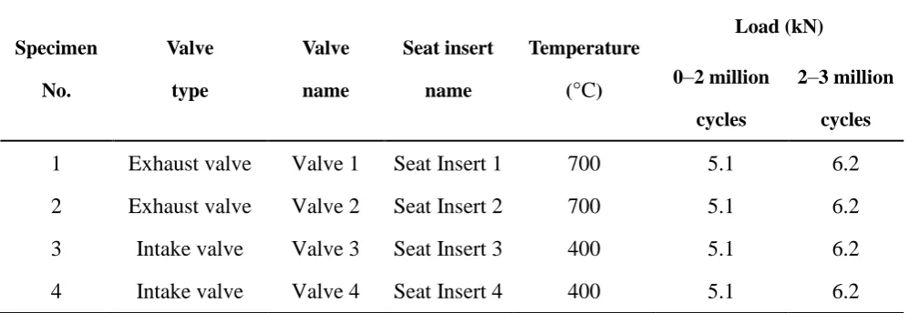
[image:10.595.76.501.315.696.2]10 / 30
Table 5 Conditions of wear test.
Specimen No. Valve type Valve name Seat insert name Temperature
(°C)
Load (kN)
0–2 million
cycles
2–3 million
cycles
1 Exhaust valve Valve 1 Seat Insert 1 700 5.1 6.2
2 Exhaust valve Valve 2 Seat Insert 2 700 5.1 6.2
3 Intake valve Valve 3 Seat Insert 3 400 5.1 6.2
4 Intake valve Valve 4 Seat Insert 4 400 5.1 6.2
2.3 Stress analysis by FEM
As the combustion pressure in the cylinder applies a load on the valve head, micro-sliding
occurs on the interface of valve seating face and seat insert. Based on the research results of
Forsberg et al. [17] and Lewis and Dwyer-Joyce [2, 18], sliding in the sealing interface was one
of the major reasons for the wear of engine valves and seat inserts. In addition, because the
difference of valve material, test temperatures, initial contact width and angle of the seating face
between the intake valves and exhaust valve, the relationship between sliding length and
geometry of the valves and seat inserts had to be determined.
2.3.1 Simulation set-up 1
In the research work of Forsberg et al. [17], unique experimental data of sliding distance
between engine valve and seat insert was acquired using a dedicated technique in a test-rig. The
experimental data is complemented and validated by FEM simulations. To validate the sliding
length simulation results in this work, the same geometry with one simulation setting of
Forsberg et al. was modelled as follows: the valve head diameter was 41 mm, seating face angle
11 / 30
0.4, and the corresponding calculated combustion pressure was 20 MPa. The full contact length
between valve and seat insert was set at 1.9 mm, 2.2 mm and 2.5 mm, respectively. The
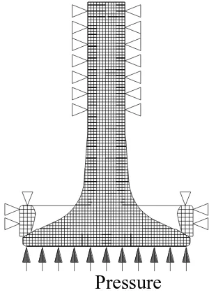
schematic diagram of simulation set-up 1 is presented in Fig. 3. The constraints are presented by
the triangular symbols pointing the constrained direction of the relevant node. Note that the
actual sliding length will be twice that of the simulated sliding length, because the surfaces will
[image:12.595.230.380.247.458.2]slide the same distance again during unloading [17].
Fig. 3 Schematic diagram of valve and inset insert FEM model for simulation set-up 1.
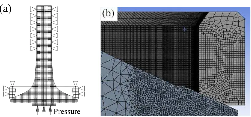
2.3.1 Simulation set-up 2
Based on the force conditions of the valve specimens during the bench-top test, the FEM model
was established as illustrated in Fig. 4(a). No seating angle difference was set between the valve
and seat insert. According to the geometry information of the valve and seat insert, a three
dimensional model was established. Then, mechanical properties of the material at the tested
temperature (Table 2) were used as inputs for the material properties of the FEM model.
Element mesh refinement (with element size was set at 0.18 mm) was used in the contact zone
to improve the calculation accuracy, as presented in Fig. 4(b). Between the seating zone of the
12 / 30
valve and seat insert contact elements with COF have been introduced.
In the former work of Qu et al. [19, 20], the friction and wear characteristics of 23-8N steel
(austenitic engine valve steel) and 42Cr9Si2 steel (martensitic engine valve steel) against
3Cr3Mo3W2V die steel were respectively investigated at high temperature. At the temperature
range from 400 °C to 650 °C, the average COF of 23-8N steel on steady state varied in the range
from 0.35 to 0.65 [19]. At the temperature range from 200 °C to 400 °C, the average COF of
42Cr9Si2 steel on steady state varied in the range from 0.4 to 0.7 [20]. As reported by Sun et al.
[21], the COF of TiAl alloy against GH3128 nickel-based superalloy was about 0.27 and 0.36 at
800 °C with two sliding speeds. The wear test of TiAl alloy against Si3N4 at elevated
temperatures is reported by Kang et al. [22]. At the temperatures from 25 °C to 900 °C, the COF
of TiAl slightly decreased from 0.42 to 0.39. Although the material of matched specimens in the
sliding wear tests were not real seat insert materials, the value of COF could be used.
Consequently, the COF of the contact element in simulation set-up 2 was respectively set in the
range from 0.1 up to 0.7 with 0.1 intervals. The simulation was carried out using ANSYS 14.0
software.
Fig. 4 (a) Schematic diagram of valve and inset insert FEM model for simulation set-up 2,(b)
(a)
[image:13.595.101.509.522.713.2]13 / 30
schematic of element mesh refinement in the contact zone.
3. Results and discussion
3.1 FEM stress analysis results
3.1.1 Results of simulation set-up 1
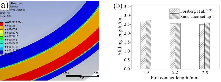
The sliding distance of one of the simulation set-up 1 is presented in Fig. 5 (a), and the
comparison of results between simulation set-up 1 and results from Forsberg et al. is presented
in Fig. 5 (b). It could be inferred that, the FEM method employed in this paper could be verified
by the results reported by Forsberg et al. [17].
Fig. 5 (a) Sliding distance of simulation set-up 1; (b) the comparison of results of simulation
set-up 1 and results from Forsberg et al. [17].
3.1.2 Results of simulation set-up 2
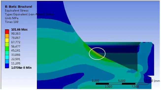
The typical FEM stress analysis result of von Mises stress distribution is presented in Fig. 6.
Due to the loading on the valve head during the wear test, for the valve, except for the contact
area, the concave area suffered the maximum stress, as indicated by the circle in Fig. 6. It is also
reported by Worthen and Rauen that the concave area of engine valve withstood the maximum
[image:14.595.80.533.308.477.2]14 / 30
Fig. 6 Typical results of von Mises stress with a load of 6.2 kN.
The contact status of the surface of the interface between valve and seat insert is presented in
Fig. 7 (a). Most of the contact area was in sticking status (red area), and the narrow area outside
the red area was in sliding status, which is indicated by the arrow in the figure. The sliding
distance is presented in Fig. 7 (b). The maximum sliding distance value occurred in the outside
diameter direction, and a slightly lower value existed near the inside diameter direction. The
sliding distance gradually decreased towards both the outside and inside contact area edges. The
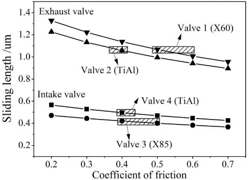
micro-sliding distance of four contact pairs with different COFs is presented in Fig. 8. With a
same value of COF, the sliding length of exhaust valve contact pairs was higher than intake
valves, due to the more serious performance degradation of materials at higher elevated
temperatures. Although lack of real COF of the valve and seat insert material at elevated
temperatures, the COF values of similar materials could be used. For instance, the COF of
martensitic 42Cr9Si2 steel against 3Cr3Mo3W2V die steel at 400 °C was about 0.4 [20], so the
COF of martensitic X85 steel at 400 °C was possible from 0.4 to 0.5. The very possible regions
of COF values for four contact pairs are indicated in Fig. 8. Then, the corresponding calculated
[image:15.595.144.471.59.243.2]15 / 30
that of Valve 2, and the sliding length of Valve 4 was higher than that of Valve 3. As the total
number of impact cycles increased, the full contact length between valve and seat insert
[image:16.595.139.476.147.495.2]increased, the sliding distance slightly decreased under the same loads.
Fig. 7 Typical results of simulation set-up 2: (a) contact status; (b) contact sliding distance.
[image:16.595.177.434.534.720.2]16 / 30
The wear volume result from sliding could be calculated by Archard's wear equation, as
presented in Equation (1) [24].
KLS W
H
(1)
where W is total wear volume, K is wear coefficient, L is total normal load, S is sliding length,
and H is the hardness of the softest surface. During the bench-top wear test, the loads of the four
valve contact pairs were kept the same. Thus, the wear loss generated by sliding was influenced
by the sliding length and the hardness of the softest materials. Based on Archard's wear equation
and the results of sliding length in Fig. 8 and the hot hardness of the engine valve and seat insert
in Table 3, it is inferred that: the wear loss of exhaust contact pairs would be higher than that of
the intake contact pairs, the wear loss of the TiAl exhaust valve would be lower than that of the
X60 exhaust valve.
3.2 Wear resistance behaviour
3.2.1 Wear scar of valve seating face
The main problem is the wear loss of the seating face of the valve and seat insert. Wear loss is a
complex process which is affected by materials and test conditions and the time (impact cycles).
An image of the surface of the Valve 2 seating face after two million impact cycles is presented
in Fig. 9(a). The wear scar profile of Valve 2 after three million impact cycles is shown in Fig.
9(b). Based on the 2D wear scar profile, the wear scar area was calculated. Fig. 9(c) reveals the
wear scar area of the four valve seating faces after three million impact cycles, and error bar in
the figure represents the standard deviation of the wear scar area. For exhaust valves, compared
to the heat resistant steel valve (X60), the wear scar area of the TiAl valve decreased from
17 / 30
700 °C. For intake valves, compared to heat resistant steel valve (X85), the wear scar area of
TiAl valve increased from 0.0875 mm2 to 0.3588 mm2. The low wear loss of Valve 3 can be
attributed to the quenching treatment on valve seating face, the material could obtain high
hardness at 400 °C, leading to a better wear resistance. For the two TiAl valves, however, the
wear loss of valve at 700 °C was lower than that at 400 °C, and cannot be explained by the
hardness of materials, so will be discussed later in conjuction with the wear mechanisms.
Fig. 9 (a) Valve 2 after two million impact cycles; (b) the wear scar profile of Valve 2 after three
million impact cycles; (c) wear scar area of the four valve seating faces.
3.2.2 Wear scar of seat insert
Fig.10 (a) presents the wear scar profiles of a seat insert seating faces after a wear test. The
[image:18.595.78.501.248.598.2]18 / 30
error bars represent the standard deviation of the calculated wear scar area. It was found that the
material loss magnitude of seat insert was different with the matched valve. The wear loss of
exhaust seat inserts was generally higher than intake seat inserts, due to the higher test
temperature. Compared to the wear loss of Seat Insert 1 and Seat Insert 3, the wear loss of Seat
Insert 2 and Seat Insert 4 (matched with TiAl valves) obtained a higher variation range at
different measurement points, indicating that more serious misaligned wear scars occurred.
Fig.10 (a) The wear scar profile of Seat Insert 2; (b) wear scar area of the four seat insert seating
faces.
3.2.3 Total wear of the contact pair
Fig. 11 presents the total wear area of four contact pairs. The wear loss of exhaust contact pairs
was higher that intake contact pairs, which was same with the analysis results of simulation 2.
For every contact pair of valve and seat insert, the wear scar area of a seat insert occupied a
higher proportion than a valve. For exhaust valve contact pairs, the total wear of the TiAl valve
contact pair was significantly lower than the austenitic steel valve contact pair (X60). However,
for the intake valve contact pairs, the total wear of the TiAl valve contact pair was even a little
[image:19.595.87.500.250.397.2]19 / 30
Fig. 11 Total wear area of four contact pairs of valve and seat insert.
Valve recession was calculated as per the method put forward by Lewis and Dwyer-Joyce [18],
and the schematic of valve recession calculation is presented in Fig. 12(a). The valve recession
followed the variation trend of total wear of contact pairs, as shown in Fig12(b). After an
adjustment of valve stem clearance, the permissible maximum value of valve recession for the
natural gas fuelled diesel is 1.3 mm. Due to the dry sliding and impact test conditions in the
bench-top wear tests, the rate of valve recession was significantly higher than that in an actual
engine. The lower rate of valve recession in a real operation engine is attributed to the protective
tribofilms formed on the contact surfaces between valves and seat inserts [25].
As reported by Ouyang et al. [9], after a 48 hour test on a diesel engine, compared to heat
resistant steel engine valve (21-4N), the valve recession of TiAl exhaust engine valve decreased
to one-eighth. In addition, it is also reported by Li and Luo [10], the valve recession of TiAl
valves was almost same with the original exhaust valve recession in a same diesel. Compared to
the work conditions of valves in the dynamometer engine test, although it is hard to achieve the
same test conditions in the bench-top test in this work, the results still could be used as a quick
20 / 30
Consequently, it is concluded that the TiAl alloy is probably a potential solution for exhaust
valves of a natural gas fuelled diesel. However, TiAl alloy is probably not suitable for intake
valves.
Fig. 12 (a) Schematic of valve recession calculation; (b) valve recession of specimens.
3.3 Worn surface and wear mechanisms
3.3.1 Worn surface of valve seating face
Fig. 13 and 14 exhibit the wear morphology found on the seating face of Valve 1 and Valve 3,
respectively. The corresponding EDS results of worn surfaces and non-contact surfaces are
listed in Table 6. Adhesive traces were found on the worn surfaces of Valve 1, as presented in
Fig. 13(b). Due to the softening of the heat resistant steel (X60) and the descending of its
strength at 700 °C, the debris generated from the closing impact began to be oxidized, forming
poorly adherent oxide layers at the high temperature test conditions. Oxide layers were broken
by shearing stress under the sliding action of the rubbing surfaces. EDS results (Table 6) of the
adhesive traces show that they contained high oxygen content. Meanwhile, compared to the
non-contact area of the valve seating face, copper and tungsten e were also detected on the worn
surface (Table 6), indicating that the seat insert material was transferred to the valve seating face
[image:21.595.79.498.150.318.2]21 / 30
[26], seat insert materials were detached and adhered on the valve's surfaces.
Compared to the Valve 1, the tribological layers on the worn surface of Valve 3 was shown to be
more compact, as presented in Fig. 14(b) and (c). Thanks to the quenching treatment for Valve 3
seating face, the material could obtain high hardness at 400 °C, leading to a better wear
resistance of the seating surface and its oxide layers. Thus, the wear loss of Valve 3 held the
minimum value, but the matched Seat Insert 3 suffered the maximum wear loss (wear loss
proportion of corresponding contact pair).
[image:22.595.79.499.273.460.2]
Fig. 13 Worn surfaces ofValve 1 seating face and EDS test area.
22 / 30
Fig. 14 Worn surfaces ofValve 3 seating face and EDS test area.
Table 6 EDS results of the areas on valve seating face (wt. %).
Specimen Area C O Si V Cr Mn Fe Ni Mo Cu W Valve 1 V1-N 9.79 5.90 0.31 0.25 14.04 0.60 66.63 0.45 2.03 – –
Valve 1 V1-C 8.12 22.96 – 0.75 12.21 – 46.14 – 4.55 3.81 1.6
Valve 3 V3-N 12.70 20.98 – 1.08 23.7 6.28 35.48 – – – –
Valve 3 V3-C 6.79 32.10 – 0.67 8.35 3.15 38.59 0.81 5.44 2.11 2.00
3.3.2 Worn surface of seat insert
Impact and micro sliding are the main reasons to describe the wear loss of engine valve contact
pairs [2, 17, 18]. With the increase of impact cycles, the wear debris may be generated from both
sides of the sealing interface. Then, these were compacted into thin layers that were attached to
the surfaces by contact adhesion. The worn surfaces of the four seat insert are presented in Fig.
15–18, and the corresponding EDS results of worn surfaces and non-contact surfaces are listed
in Table 7. Adhesive wear is characterized by bonding and subsequent breakage occurring
alternately between sliding materials. Adhesive traces were identified on the worn surfaces of
[image:23.595.39.572.297.419.2]23 / 30
adhesive traces show that they contained high oxygen content, so the wear rate was accelerated
by some type of oxidative wear due to the elevated temperatures. Combined with the analysis of
the worn surface of Valve 1, the wear mechanisms of exhaust valve contact pairs are concluded
to be oxidative wear combined with adhesive wear.
The hardness of the TiAl alloy kept almost the same when the temperature lower than 700 °C
(Table 3), thus the hardness of Valve 2 and Valve 4 were at a same level. However, the hardness
of Seat Insert 2 was inferred to be much lower than Seat Insert 4. Compared to Valve 4, the
lower wear loss of Valve 2 may be attributed by the lubrication role of oxide layers on its worn
surface. The oxide layer acted as a "crash pad" to avoid the direct contacting (metal to metal) of
contact pairs to some extent. Because the lower hardness of Seat Insert 2, its wear loss was
higher than Seat Insert 4. At last, the total wear of the TiAl exhaust valve contact pair was a bit
higher than the TiAl intake valve contact pair. Surface treatment should be introduced to the
TiAl valve, for instance, plasma carburizing is effective in improving wear resistance on the
valve stem and seating face [5].
Material transfer phenomena were also identified on the worn faces of seat inserts. As presented
in Table 7 (area of S2-C and S4-C), the Aluminium and Titanium element were also detected on
the Seat Insert 2 and Seat Insert 4, since they were matched with TiAl valves. Based on the EDS
results from Table 6 and 7, it is proved that the transferring behaviour of materials between the
valve seating surface and seat insert indeed existed. The associated wear mechanism thus included
adhesive wear.
Both peeling and adhesive traces of materials were found on the worn surfaces of Seat Insert 3,
24 / 30
shown to be more compact, as presented in Fig. 18(b). The worn surfaces of Seat Insert 3 and 4
also contained oxygen content to some extent, as presented in Table 7. Compared to the exhaust
valve contact pairs tested at 700 °C, the contact adhesion on the seating face of intake valve and
seat insert, as well as the generated wear debris could obtain a higher hardness at 400 °C. The
contact adhesion would be broken, and more likely due to the increased weakening of the surface
through oxidative wear, and fragments of material detach from the worn surfaces and act as third
bodies. Consequently, it is observed the micro-plowing and ground fragments on the worn
surface of Seat Insert 3, as presented in Fig. 17(c) and (d). The predominant wear mechanisms
can be identified as abrasive wear and adhesive wear.
[image:25.595.77.501.336.522.2]
Fig. 15 Worn surfaces of Seat Insert1.
25 / 30
Fig. 16 Worn surfaces of Seat Insert2.
[image:26.595.80.498.492.680.2]
Fig. 17 Worn surfaces of Seat Insert 3.
26 / 30
Table 7 EDS results of the areas on seat insert seating face (wt. %).
Specimen Area O V Cr Mn Fe Co Ni Mo Cu W Al Ti Seat Insert 1 S1-N 3.58 3.23 6.16 – 62.08 8.12 1.48 4.94 6.62 3.80 – –
Seat Insert 1 S1-C 37.32 2.04 4.77 0.66 43.25 5.38 1.03 – 4.77 0.77 – –
Seat Insert 2 S2-C 21.43 1.31 4.01 2.10 28.64 3.86 – 5.72 11.26 2.59 4.12 14.95
Seat Insert 3 S3-C 20.14 1.12 6.50 – 53.16 6.55 – 3.13 5.95 3.45 – –
Seat Insert 4 S4-C 6.62 – 2.19 5.02 20.01 1.98 – 2.65 3.69 1.02 17.89 38.93
4. Conclusions
The wear behaviour of heat resistant steel engine valves and TiAl engine valves were compared
through bench-top wear tests. The conclusions can be drawn as follows:
(1) Compared to the austenitic exhaust valves tested at 700 °C, the TiAl valve had better wear
resistance, the wear loss decreased by 24.8 %. The predominant wear mechanism is considered a
combination of oxidative wear and adhesive wear.
(2) Compared to the martensitic intake valves tested at 400 °C, the wear loss of the TiAl valve
was four times as much as martensitic intake valves. The predominant wear mechanism can be
identified as abrasive wear and adhesive wear
(3) The TiAl exhaust valve is a potential solution for a natural gas fuelled diesel ICE.
Acknowledgements
The authors wish to express the most sincere appreciation to Chairman Tao Zhang from Huaiji
Dengyun Auto–parts (Holding) Co., LTD. The authors wish to thank Senior Engineer Dongqiang
Mo, Wenlan Fu, Gang Chen, Ge Sun and Engineer Qi Huang, Deci Kong from Huaiji Dengyun
27 / 30
for the paper. Senior engineer Yanjun Xin from Weichai Power Company Limited provided TiAl
alloy valves and professional guidance for the bench-top wear test. This study was sponsored by
the Guangdong Province Scientific and Technological Projects (No. 2016KZ010104). The
authors acknowledge the financial support from the China Scholarship Council (File No.
201706150079). The work was also supported by the open fund project of State Key Laboratory
of Engine Reliability (SKLER-201705).
Conflicts of Interest: The authors declare no conflict of interest.
References
[1] YS Wang. Introduction to engine valvetrains. Warrendale: SAE International; 2007.
[2] R Lewis, RS Dwyer-Joyce. Automotive engine valve recession. London: Engineering research
series, 2002.
[3] M Badami, F Marino. Fatigue tests of un-HIP’ed -TiAl engine valves for motorcycles. Int J
Fatigue 2006; 28:722–732.
[4] H Clemens, S Mayer. Intermetallic titanium aluminides in aerospace applications–
processing, microstructure and properties. Mater High Temp 2016; 33(4-5): 560–570.
[5] K Maki, A Ehira, M Sayashi, T Sasaki, T Noda, M Okabe, S Isobe. Development of a
high-performance TiAl exhaust valve. SAE 960303, 1996.
[6] WE Dowling, Jr JE Allison, LR Swank, AM Sherman. TiAl-based alloys for exhaust valve
applications. SAE 930620, 1993.
[7] M Blum, G Jarczyk, H Scholz, S Pleier, P Busse, HJ Laudenberg, K Segtrop, R Simon.
Prototype plant for the economical mass production of TiAl-valves. Mat Sci Eng A-Struct
28 / 30
[8] PX Fu, XH Kang, YC Ma, K Liu, DZ Li, YY Li. Centrifugal casting of TiAl exhaust valves.
Intermetallics 2008; 16: 130–138.
[9] HW Ouyang, BY Huang, YH He, Y Liu, AX Li. Development of TiAl-based automotive
engine exhaust valves. The Chinese Journal of Nonferrous Metals 2000; 10 (Suppl 1): 60–63
[in Chinese].
[10] JM Li, ZR Liu. The study of exhaust valve of Tilanium-aluminium alloy in diesel engine
testing. Journal of Hunan university (Natural Sciences Edition) 2001; 28(2): 32–34 [in
Chinese].
[11] ZR Zhang, YS Sun, XJ Lin, DQ Mo, G Sun, G Chen, DT Su, ZY Li, WQ Qiu, BY Wang, JP
Liu. A forming technology for hollow head & sodium filled engine valve which based on
cross wedge rolling to produce workblank. China patent, ZL 201510236950.9. 2017-10-27
[in Chinese].
[12] FQ Lai, SG Qu, Y Duan, R Lewis, T Slatter, LM Yin, XQ Li, HH Luo, G Sun. The wear
and fatigue behaviours of hollow head & sodium filled engine valve. Tri. Int. 2018;
128:75–88.
[13] FQ Lai, SG Qu, LM Yin, GH Wang, ZX Yang, XQ Li. Design and operation of a new
multifunctional wear apparatus for engine valve train components. Proc. IMechE, Part J: J
Engineering Triblogy 2018; 232(3): 259–276.
[14] MS Baniasad, E Khalil, F Shen. Exhaust valve thermal management and robust design
using combustion and 3d conjugate heat transfer simulation with 6-sigma methodology. SAE
2006-01-0889, 2006.
29 / 30 numbers. Wear 2007; 263: 1147–1157.
[16] YS Wang, S Narasimhan, JM Larson, JE Larson. GC Barber. The effect of operating
conditions on heavy duty engine valve seat wear. Wear 1996; 201:15–25.
[17] P. Forsberg, D. Debord b, S. Jacobson. Quantification of combustion valve sealing interface
sliding – A novel experimental technique and simulations. Tri. Int. 2014; 69:150–155.
[18] R Lewis, RS Dwyer-Joyce. Wear of diesel engine inlet valves and seat inserts. Proc.
IMechE, Part D: J of Automobile Engineering 2002; 216(3): 205–216.
[19] SG Qu, LM Yin, FQ Lai, et al. High temperature friction and wear properties of 23-8N
valve steel. Journal of South China University of Technology (Natural Science Edition) 2017;
45(12):.78–84 [in Chinese].
[20] SG Qu, LM Yin, FQ Lai, CW Xiao, XQ Li. Study on High temperature friction and wear
characteristics of 4Cr9Si2 valve steel. Advances in Mechanical Design. ICMD 2017.
Mechanisms and Machine Science, Springer, Singapore, 2017; 55: 1535-1546.
[21] DL Sun, T Sun, Q Wang, XL Qin, LL Guo. Friction and wear properties of TiAl and
Ti2AlN/TiAl composites at high temperature. J. Wuhan Univ. Technol. 2013; 28(5):
1023–1028.
[22] K Yang, XL Shi, YC Huang, ZH Wang, YF Wang, A Zhang, QX Zhang. The research on the
sliding friction and wear behaviours of TiAl-10 wt% Ag at elevated temperatures. Mater.
Chem. Phys. 2017; 186: 317–326.
[23] RP Worthen, DG Rauen. Measurement of valve temperatures and strain in a firing engine.
SAE 860356, 1986.
30 / 30
[25] JM Li, ZR Liu. The study of exhaust valve of Tilanium-aluminium alloy in diesel engine
testing. Journal of Hunan university (Natural Sciences Edition) 2001; 28(2): 32–34 [in
Chinese].
[26] LAB Mascarenhas, JDO Gomes, VE Beal, AT Portela, CV Ferreira, CA Barbosa. Design
and operation of a high temperature wear test apparatus for automotive valve materials.

![Table 2 Mechanical properties of engine valve materials [3, 5].](https://thumb-us.123doks.com/thumbv2/123dok_us/1867539.143777/8.595.75.541.493.662/table-mechanical-properties-engine-valve-materials.webp)