analysis of energy efficient sintering technologies in the functional materials sector
.
White Rose Research Online URL for this paper:
http://eprints.whiterose.ac.uk/151475/
Version: Published Version
Article:
Ibn-Mohammed, T., Randall, C.A., Mustapha, K.B. et al. (7 more authors) (2019)
Decarbonising ceramic manufacturing : a techno-economic analysis of energy efficient
sintering technologies in the functional materials sector. Journal of the European Ceramic
Society, 39 (16). pp. 5213-5235. ISSN 0955-2219
https://doi.org/10.1016/j.jeurceramsoc.2019.08.011
[email protected]
https://eprints.whiterose.ac.uk/
Reuse
This article is distributed under the terms of the Creative Commons Attribution (CC BY) licence. This licence
allows you to distribute, remix, tweak, and build upon the work, even commercially, as long as you credit the
authors for the original work. More information and the full terms of the licence here:
https://creativecommons.org/licenses/
Takedown
If you consider content in White Rose Research Online to be in breach of UK law, please notify us by
Contents lists available atScienceDirect
Journal of the European Ceramic Society
journal homepage:www.elsevier.com/locate/jeurceramsoc
Original Article
Decarbonising ceramic manufacturing: A techno-economic analysis of
energy e
ffi
cient sintering technologies in the functional materials sector
T. Ibn-Mohammed
a,b,c,d,h,⁎, C.A. Randall
d,⁎⁎, K.B. Mustapha
e, J. Guo
d,f, J. Walker
g, S. Berbano
d,
S.C.L. Koh
b,c, D. Wang
h, D.C. Sinclair
h, I.M. Reaney
h,⁎⁎aWarwick Manufacturing Group (WMG), The University of Warwick, Coventry, CV4 7AL, UK bCentre for Energy, Environment and Sustainability, The University of Sheffield, Sheffield, S10 1FL, UK cAdvanced Resource Efficiency Centre, The University of Sheffield, Sheffield, S10 1FL, UK
dMaterials Research Institute, The Pennsylvania State University, University Park, PA, 16802, USA
eDepartment of Mechanical, Materials and Manufacturing Engineering, University of Nottingham, Malaysia Campus, 43500, Malaysia fState Key Laboratory for Mechanical Behaviour of Materials, School of Materials Science and Engineering Xi
’an Jiaotong University, Xi’an, 710049, China
gDepartment of Materials Science and Engineering, Norwegian University of Science and Technology, NO-7491, Trondheim, Norway hDepartments of Materials Science and Engineering, The University of Sheffield, Sheffield, S1 3JD, UK
A R T I C L E I N F O
Keywords: Sintering techniques Ceramics manufacturing Energy reduction Energy efficiency Techno-economic analysis Investment appraisal
A B S T R A C T
The rising cost of energy and concerns about the environmental impact of manufacturing processes have ne-cessitated the need for more efficient and sustainable manufacturing. The ceramic industry is an energy intensive industrial sector and consequently the potential to improve energy efficiency is huge, particularly through the introduction of modern sintering technologies. Although several energy efficient sintering processes have been developed, there is no comprehensive techno-economic analysis which compares and contrasts these techniques. This paper presents a critical review and analysis of a number of sintering techniques and compares them with the recently developed cold sintering process (CSP), including mode of operation, sintering mechanism, typical heating rates, duration of sintering, energy consumption profile and energy saving potential, limitations, key challenges for further development and current research efforts. By using afigure of merit, pounds per tonne of CO2saved (£/tCO2-eq), which links initial capital investment with energy savings, within a framework derived from ranking principles such as marginal abatement cost curves and Pareto optimisation, we have demonstrated that under the scenarios considered for 3 separate functional oxides ZnO, PZT and BaTiO3, CSP is the most economically attractive sintering option, indicating lower capital costs and best return on investment as well as considerable energy and emission savings. Although the current work establishes the viability of CSP as a competitive and sustainable alternative to other sintering techniques, the transition from laboratory to industry of CSP will require hugely different facilities and instrumentation as well as relevant property/performance validation to realise its full potential.
1. Introduction
1.1. Industrial emissions and the quest for reduction
An analysis of sources of emissions by economic sectors indicates that the industrial sector is a key consumer of the global primary energy supply, and therefore a major contributor to global emissions and its associated environmental pollution and impact. For instance, 21% of the economic activities that led to the production of emissions and re-lated pollutants in 2010 was attributed to the industrial sector (Fig. 1a)
[1]. This represents a 43% increase in total global emissions from 2005 when the emissions attributed to industrial sector was 14.7%, in-dicating that the sector is an integral component to addressing energy and environmental pollution issues [2]. The International Energy Agency [3] also reported that between 1990 and 2014, direct GHG emissions in the industrial sector increased by roughly 70%, but during the same time frame, the economic output of the sector increased at a slightly faster pace than its GHG emissions leading to 5% reduction of direct GHG emissions per unit of economic output,Fig. 1b. This sug-gests that although the sector consumes considerable energy and
https://doi.org/10.1016/j.jeurceramsoc.2019.08.011
Received 8 April 2019; Received in revised form 1 August 2019; Accepted 7 August 2019
⁎Corresponding author at: Warwick Manufacturing Group (WMG), The University of Warwick, Coventry, CV4 7AL, UK.
⁎⁎
Corresponding authors.
E-mail addresses:[email protected](T. Ibn-Mohammed),[email protected](C.A. Randall),i.m.reaney@sheffield.ac.uk(I.M. Reaney).
Available online 11 August 2019
0955-2219/ © 2019 The Author(s). Published by Elsevier Ltd. This is an open access article under the CC BY license (http://creativecommons.org/licenses/BY/4.0/).
contributes to high emissions and environmental pollution, it remains key to delivering the global efforts towards a low-carbon economy, whilst contributing to its growth and balance. This is evident, given that much of the economic growth experienced by emerging markets today is triggered by developments in industrial and manufacturing activities that require greater resource inputs, leading to overall increase in the environmental impact of the sector.
As illustrated inFig. 1b, to achieve significant improvements in the industrial sector, emissions, both direct and indirect, will require turnaround from growth to a steep drop to attain 2050 targets. Given that the industrial sector accounts for 28% of global GHG emissions in 2014, it follows that the set targets cannot be attained without dec-arbonising the sector. The decarbonisation of the industrial sector is therefore the next frontier after the significant breakthroughs and successes recorded in the building, transport and power sectors, due to the scaling up of decarbonisation technologies. As such, energy efficient and sustainable manufacturing processes based on advanced technolo-gies with reduced energy costs and lower environmental impact have
become an important research focus [4–8].
1.2. Energy consumption and CO2emissions in the ceramic industry
[image:3.595.87.515.60.493.2]The conservation of energy is a vital step that must be taken in order to overcome the escalating problems of global energy crisis and en-vironmental impact. One of the energy intensive industrial sectors that has the potential to improve efficiency by leveraging modern energy reduction technologies is the ceramic industry [9]. As such, the sector was given a special attention and consideration towards decarbonisa-tion efforts in the recently published Industrial Decarbonisation and Energy Efficiency Roadmaps to 2050 commissioned by the Department for Business, Energy & Industrial Strategy (BEIS) [10]. As one of humanity’s oldest industries through which the greatest and earliest achievements were recorded, the ceramic industrial sector is a future-oriented sector with enormous strategic importance, given its ability to contribute towards the development of a competitive resource-efficient and low-carbon economy in the years ahead [11].
With its expansive array of applications, ranging from consumer goods, construction, through to cutting-edge technologies and manu-facturing processes, the ceramic industry is at the forefront of devel-oping high-value and innovative solutions that improve quality of life whilst enabling crucial progress in downstream sectors [10,11]. Indeed, products from the sector play a significant and very often indispensable function in realising energy and resource efficiency in other sectors. By facilitating energy and resource efficiency in all these allied sectors, ceramics play a vital role in the society. In the UK, for example, the sector yielded over four million tonnes of a wide range of products in 2012, whilst contributing a direct value of £1 billion equivalent to its economy [10].
The ceramic industry consumes much energy and by extension high CO2 emission because it utilises specific chemical and mechanical processes for the conversion of raw materials into a malleable solid, powder or slurry, constituting a large percentage of the energy cost in the overall production cost. Electricity consumption represents up to 30% of the production cost in ceramics processing, although it varies based on product type and cost of fuel [12]. This is particularly the case in the UK where the total emissions attributed to ceramic installations in 2012 is 1.2 Mt CO2-eq, with fuel costs constituting roughly 35% of total manufacturing costs [10].Fig. 2shows the percentage distribution of energy cost attributed to manufacturing cost by industry in Japan, for example [13]. As indicated, the percentage of the ceramic industry (including glass, pottery and cement) is 8.9%. A reduction in energy use and cost can therefore lower the production cost, whilst generating an immediate impact on profit.
As highlighted above, all the subsectors within the ceramic in-dustrial sector are energy intensive given an integral part of the process entails drying followed by sintering at very high temperatures of be-tween 800 °C and 2000 °C [14]. Sintering is a form of heat treatment to which powder compact is subject with the aim of imparting strength and integrity. It is the procedure for compacting and forming a solid mass of material with the aid of heat or pressure without melting to the point of liquefaction. Over 60% of the 10,700 T J consumed by the UK ceramics sector is utilised for sintering [12]. In the quest to reduce the
energy consumption, carbon footprint, energy costs, environmental impact and protect world resources, it has been established that tradi-tional firing or sintering process may now become unnecessary for many ceramic materials, given that a broad spectrum of inorganic materials and composites can also be sintered between room tempera-ture and 200 °C, using the cold sintering process (CSP) developed by Randall and co-workers [15–18]. CSP relies on a second phase that facilitates mass transfer for densification, a process that occurs at low temperatures and over much shorter time frames, minutes instead of hours, when a uniaxial pressure is applied [15–18]. Mostly, these phases produce liquids that evaporate during the process. The transient liquid drives the densification via a solution-precipitation process [15–18].
1.3. Research gap and specific objectives
Despite the upsurge in research interests relating to developing low temperature sintering process, techno-economic analyses of CSP alongside existing sintering techniques such as traditional and Spark Plasma Sintering (SPS) is lacking. Understanding the potential techno-economic impact of sintering techniques, manufacturing routes and materials composites is essential, and it is crucial that such an under-standing commence at the design stage and/or at laboratory stage, not after they are fully scaled up or used. This research need is addressed in this paper using a robust techno-economic analysis framework derived from ranking mechanisms of marginal abatement cost curve (MACC) and Pareto optimisation. This allows us to classify sintering techniques into those that are able to reduce energy consumption and save money and those that may reduce energy consumption but require a net in-vestment at the level of the laboratory.
[image:4.595.141.460.476.729.2]Specifically, the objectives of the paper are to: (i) carry out a brief review of a number of sintering techniques to highlight and compare their potential towards energy consumption reduction during ceramic processing; (ii) develop a robust mathematical modelling of energy consumption in parts fabrication via sintering; (iii) establish the via-bility of cold sintering as a competitive and sustainable alternative to
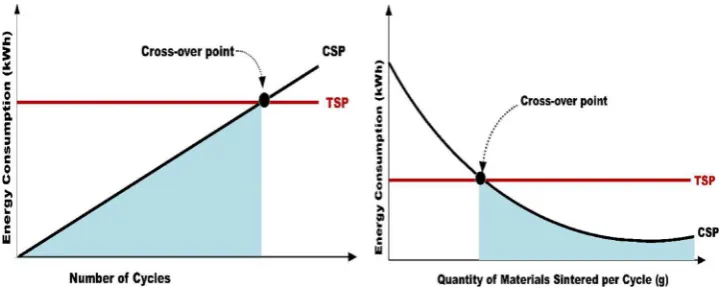
other traditional high temperature ceramic manufacturing techniques, using three functional ceramics, ZnO, PZT and BaTiO3; (iv) develop different scenarios within a techno-economic analysis (TEA) framework to model the identified synthesis and sintering routes as well as energy and mass inputs; (v) establish the cross-over point between cold sin-tering techniques and other sinsin-tering techniques with the view to identify which parameters to be optimised when transitioning from laboratory to the industry; and (vi) establish an appropriatefigure of merit that links financial cost with energy savings, for comparing all sintering techniques under consideration. This will lead to the optimal ranking of the cost-effectiveness of each sintering technique with re-spect to their energy saving potentials.
In light of the above, the remainder of the paper is organised as follows. In Section2, a critical review of a number of sintering tech-niques is provided. Detailed mathematical modelling of a generalised energy equation which governs the sintering techniques is provided in Section3. In Section4, the overall methodological framework under-pinning the techno-economic analysis within a MACC framework and Pareto optimisation principle is provided. In Section5, the keyfindings from the analysis are discussed alongside a robust sensitivity analysis, highlighting the implications of the work to novel sintering techniques leading to the limitations as well the summary and concluding remarks in Sections6and7respectively.
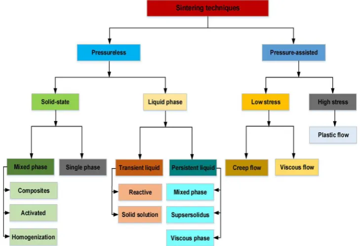
2. Critical review of selected ceramic sintering techniques
The theory of sintering is most accurately used to describe single phase powders sintered through solid state diffusion but in practice, this represent a small portion of sintering activities, given that a number of other sintering techniques entails multiple phases and liquids.Fig. 3 depicts a pictorial representation of sintering techniques in the form of a general categorisation. For a full description of each of the classified sintering techniques, we refer readers to German [19]. The subsections that follow present a review of selected sintering techniques in com-parison to cold sintering, including mode of operation and unique at-tributes, sintering mechanism (i.e. mechanistic details), electrical con-ditions (i.e. energy consumption profile), typical heating rate, duration of sintering, energy saving potential, limitations, key research and
upscaling challenges for further development and current research ef-forts.
2.1. Conventional or traditional sintering technique
Generally speaking, sintering entails the thermal treatment of powder particles at a temperature which is below the melting point of the main constituent with the view to increase the strength of the particles under consideration by bonding them together [20]. In other words, sintering entails the compacting and forming of a solid mass of material by subjecting it to heat or pressure without melting it to the point of liquefaction. Essentially, the process is used to establish a dense solid mainly aided by thermal energy and/or pressure [19]. Sintering is an integral part of the manufacturing process of functional ceramics given the control it imposes on numerous important properties of the
finished product including abrasion resistance, mechanical strength, resistance to water and chemicals, dimensional stability, conductivity and ductility as well asfire resistance [21]. Essentially, the main ob-jective of sintering is to reduce compact porosity with the view to [22]: (i) increasing the contact area of particles; (ii) rounding offpoints of contact and sharp angles; (iii) ensuring a decrement in the volume of interconnected pores and facilitating the grain growth whilst de-creasing the volume of isolated pores.
[image:5.595.115.480.469.718.2]Conventional or traditional sintering entails the heating of materials at comparatively high temperatures,T T /2> m , whereTmis the melting point, and under not too high pressure,P<0.2 GPa (2.0kBar), across a time frame from minutes to hours. These conditions ensure the adhe-sion and densification of powder through numerous diffusion depen-dent processes, including surface and grain boundary diffusion [20]. Depending on the materials under consideration, the sintering perature range for conventional sintering technique is at high tem-peratures typically > 1000 °C to facilitate the mass transport processes that allows atoms, cations or molecular groups to diffuse [16]. This mass transport mechanism reduces the surface area of the particulates whilst eliminating porosity [23]. At high temperatures, thefine parti-cles go through numerous changes from particle rearrangement, grain growth and pore elimination. In conventional sintering, energy is transported to the material via conduction and radiation of heat from
the surface (i.e. energy transfer is induced by external heating source whereby heatflow is from outside to inside and is not dependent on the materials under consideration) [24].
A major feature of the conventional sintering technique is the high sintering temperature and longer duration needed for the consolidation of the ceramic particles which often leads to extreme coarsening of grains and decomposition of the ceramic, causing the mechanical properties to deteriorate [25,26]. Due to the high melting temperature required for numerous ceramics, conventional sintering is normally accomplished between˜50%–75% of their melting points, as a rule of thumb [27]. For oxides, the temperature at which sintering takes place is typically > 1000 °C and over a few hours, though sintering profiles can extend to days [19,23]. Additionally, the chemical stoichiometry of the end product from this sintering approach may differ due to volati-lisation of elements such as Pb, Bi, K and Na or where co-firing of different materials (e.g. electrode-ceramic co-fired MLCCs) are in-volved, resulting into property and crystal structure deviation triggered by the alteration of defects concentration or intergranular diffusion [28–33].
In an effort to achieve densification at lower temperatures com-pared to conventional sintering, hot pressing has shown promise, given the improvement of the kinetics of densification and the limiting of grain growth [34,35]. Major disadvantages pertain to the constrained geometry of thefinal product and the expensive nature of the equip-ment required [22]. Additionally, in hot pressing technique, the particle container is characteristically heated by radiation from the surrounding furnace by convection of inert gases and external heating elements where applicable. As such, the material under processing is heated by transfer of heat via conduction from the external surface of the con-tainer to the particles, leading to slow heating rate and thereby elon-gating the overall duration for the sintering process [22]. For a full description of conventional sintering technique, we refer readers to German [19] and Bordia et al. [36]. Attempts to lower sintering tem-perature and by extension the sintering time have led to the develop-ment of novel sintering techniques described in the sections that fol-lows.
2.2. Microwave sintering
Microwaves are characterized by wavelengths,1 cm−1 mm, corre-sponding to300 MHz−300 GHzand are best known to the public for their strong interaction with water molecules resulting in the devel-opment of the microwave oven [37]. Microwaves are key enablers of cellular, radar, and satellite communications facilities [37] but they are also used in the processing of advanced materials via microwave-as-sisted sintering and heating [38–42]. Developments in this area have focussed on applications such as pharmaceutical [43], material joining [44,45], electronics packaging [46], and polymer curing [47,48]. This section sheds light on the evolution of microwave sintering by focusing on its mechanism, advantages, energy profile, heating rate, and chal-lenges.
A sintering process improves bonding between the particles by minimizing porosity [49]. Yet, the outcome of sintering is often greatly influenced by the underlying mechanism [50]. The traditional sintering process relies on radiant and resistive heating. In this aspect, the heat energy is transferred through thermal gradients from outside to inside of the powder compact [51,52]. In contrast, microwave sintering does not rely on diffusion of heat from the surfaces. Under irradiation, the volume of materials being sintered absorbs microwave energy and then transforms it into heat, with the heatflowing outwardly from inside to outside. The process allows a 100% transformation between electro-magnetic and thermal energy, leading to a reduction in sintering time with greater energy efficiency, enhanced reaction, faster sintering rate without cracking, reduced thermal gradients, improved quality offinal products, and low environmental impact [53–55]. In microwave sin-tering, the key parameters are appliedfield frequency, temperature of
the furnace and the concentration as well as the types of elements used for doping [56–58].
In spite of the aforementioned advantages, the microwave sintering technique is not without shortcomings. The technique requires the use of high-end expensive equipment that costs far more than for the tra-ditional sintering. This has severely hampered the broader proliferation of the process beyond exploratory laboratory demonstration set-ups [59]. Moreover, microwave sintering must be carried out inside a mi-crowave applicator with a sophisticated insulating system. This re-quirement inhibits real-time data collection and monitoring of the in-teractions of microwaves with different materials [60]. Monitoring and efficient data collection is needed to enhance the process and provide the basis for understanding the properties of a sintered volume arising from the complex interactions of the powder materials with microwave radiation [61]. It is categorized as an environmentally-friendly process and the temperature requirement for microwave sintering varies from moderate temperature range (500 −1000 ) with minimal power consumption to those above1000 (with significant power consump-tion) [62]. Nonetheless, comparisons of the temperature required to obtain fully dense samples is lower compared to conventional sintering [63].
Earlier applications of microwave sintering was predominantly re-lated to the processing of polymers and ceramics starting from the 50 s [41,50,63]. Extension of the method to sintering of metals were initially thought impossible due to the widely-held belief that metals are mi-crowave reflectors [64]. The myth was shattered by a serendipitous experimental observation in 1999 [65]. Subsequent studies following this breakthrough have revealed that powdered metal components as well as various types of metal alloys can indeed be sintered. Processing conditions are typically 2.45 GHz microwave furnace, the most common frequency for sintering applications [63,66]. For further de-tails on the comparison between microwave and conventional sintering techniques, see Oghbaei and Mirzaee [50].
2.3. Spark plasma sintering (SPS)
It was in the 1960s that spark sintering wasfirst researched and patented, with applications in metal powder compaction [22,67]. However, due to enormous equipment cost and the reduced efficiency of the sintering mechanism, its use was streamlined. By mid-1980s to early 1990s, research on the technique reached an advanced stage yielding a new generation known as Plasma Activation Sintering (PAS) and Spark Plasma Sintering (SPS) [22]. SPS is a form of pressure-as-sisted sintering which utilises low-voltage, pulsed direct current to heat up the materials under consideration [68]. The technique has attracted enormous attention by manufacturing engineers as well as materials scientists given that it guarantees a quick fabrication route to react and consolidate materials in a single processing step [68,69]. These attri-butes renders SPS an ideal approach for rapid fabrication and char-acterisation of new compositions to explore the phase of new possible materials [68,69].
With the adoption of SPS, the duration for processing powder ma-terials is significantly shortened whilst improving the overall powder consolidation. As illustrated inFig. 4, SPS allows heating and cooling at rates > 200 K/min [69] during powder consolidation as compared to the conventional sintering technique with heating rates of between 2–30 °C/min. [68]. Due to the compact geometry of the die and punches within SPS, sintering cycles with heating rates of up to 1000 °C/min have been reported [68]. Additionally, full densification takes only few minutes in comparison to several hours required by conventional hot processing technique [36].
nanopowders [36,68]. In terms of nanostructured materials processing, SPS has become a sintering technique of choice for the production of densefine-grained samples from high-melting point ceramic powders and for the preparation of phase-pure materials from precursors [69].
The sintering technique has emerged as an adaptable method of material processing for consolidation and synthesis [36,68]. It facil-itates the development of non-conductive and electrically conductive materials at the laboratory scale (with processing cycles including cooling down to room temperature of < 1 h) or the quick fabrication of industrial products [36,68]. The general mode of operation of SPS is based on a mechanical loading with a high-power electrical circuit placed in a pressure, position and temperature-controlled environment as illustrated inFig. 5. During synthesis, the sample is quickly heated by a pulse current (Joule heating) of the conductive die set while under an applied load with a corresponding increase in temperature when den-sification is observed [22]. The entire synthesis process including heating, cooling and densification which takes place in < 30 min is possible due to the spark plasma induced by the large pulsed current [22,69]. In SPS, the use of pulsed direct current indicates that the die also serves as a source of heating and that the sample is subjected to heat from both outside and inside [22]. The application of pulsed direct current results inin-situparticle surface activation and purification by the spark plasma [22,68]. Accordingly, the heat and mass transfer be-tween the particles is quickly realised.
Due to the complex nature of the different physical phenomenon in SPS, modelling of the process has posed significant challenges and clear insights are only just coming to light about the mechanism involved in
SPS including mechanical, thermal and electrical effects [36,68]. In terms of mechanical effects, the quasi-static compressive stress applied in SPS provides a number of merits such as: (i) better and improved contact between particles which changes the quantity and morphology of those contacts; (ii) enhancements of the prevailing densification mechanisms already available within free sintering (e.g. lattice diff u-sion, grain boundary diffusion and viscousflow) and (iii) activation of new mechanisms including grain boundary sliding or plastic deforma-tion [68].
From a thermal perspective, a competitive edge offered by SPS is the high rate of heating. When the central densification mechanism (e.g. grain boundary diffusion) has greater activation energy than the coar-sening mechanism (e.g. surface diffusion), attaining a fast high-sin-tering temperature can offer advantages for enhancement of the den-sification rate whilst retarding microstructure coarsening [68]. Further thermal effects of SPS pertain to increased local temperature gradients or unbalanced distribution of temperature and macroscopic tempera-turefields yielding thermal stresses [68]. From the perspective of the
flow of an electric field, if an electrical conducting raw powder is prepared by SPS, high currentsflow through the body as opposed to the surrounding graphite die. In this scenario, interactions between the electric current and the microstructure could yield useful effects such as percolation effects [70,71], Peltier heating [72], electrochemical reac-tion at the interfaces [73] and electromigration [74].
In summary, SPS is of great importance in the fabrication of bulk nanostructured parts where control of grain growth constitutes a major hindrance [75–77] but further research comparing the mechanisms of SPS and conventional sintering is required under a number of different thermally activated processes including reactive sintering [78–81], densification [74,82,83], crystal growth in both liquid and solid state [67,84] and joining [85–88]. Furthermore, upscaling to large specimen dimensions and improved flexibility based on possible product geo-metries are also required [36].
Techniques, such as microwave sintering and SPS described are generically termed as Field Assisted Sintering Technology (FAST) [89] in which an electric, magnetic or electromagnetic field are used to enhance densification [90]. Essentially, all sintering techniques based on FAST possess the ability to lessen the temperature for sintering by several hundred degrees as demonstrated when flash sintering was adopted for the fabrication offine microstructures of SrTiO3[91] and in some cases, complex multi-layer devices [92].
2.4. Flash sintering
A more recent development in FAST is the so called‘flash’sintering. Inflash sintering, samples are usually in the form of a bar and two platinum/silver wires wrapped at two ends but the overall confi gura-tion depend on the temperature at which sintering is carried out and the ensuing reaction during the sintering operation. The overall confi g-uration is normally suspended inside a furnace within an electricfield of intensity of˜1.2 kV/cm applied to the samples through the wires [93]. The electricfield enhances the process of densification based on a number of mechanism includingfield induced effects, Joule heating and interfacial energy changes [94,95]. Overall, FAST depends largely on electric field and the rate of diffusion at grain boundary which boosts diffusion [90]. A detailed description of the effect of electricfield on current, temperature profile and other factors such as resistance, dangling bonds at the surface of particles and the energy states of electron in FAST is provided by Heidary et al. [90].
By using the power consumption of FAST or Flash sintering reported by Cologna et al. [96], Heidary et al. [90] were able to calculate overall energy consumption and reported that the use of FAST can contribute to
[image:7.595.54.272.55.199.2]˜ 49% decrease in energy consumption depending on the materials under consideration. Based on this aggregated energy consumption, Heidary et al. [90] observed that the energy consumed by the furnace constitute the largest impact (i.e. about 6000 times) compared to the Fig. 4.Illustration of heating and cooling rates of SPS technique, adapted from
Gaultois [69].
[image:7.595.66.260.540.720.2]negligible energy consumption via the electric field. Despite the po-tentials of FAST, it suffers from a number of limitations including complexity of the technique as well as limitations pertaining to geo-metry given that careful consideration must be ensured such that the electricfield is applied in a homogenous fashion [90]. This is particu-larly important given that grain growth and the rate of densification differs at different electricfields [97,98]–a situation that can lead to densification and grain size inhomogeneity in the samples under con-sideration as highlighted by Todd et al. [93].
A number of other limitations of FAST/flash sintering have been reported in the extant literature [94,99–101]. As highlighted before, the majority of the energy consumption in FAST is consumed by the furnace that possess large chambers and requires a huge amount of energy to achieve the required temperature. This is further compounded by en-ergy dissipated via thermal conduction and radiation through the walls of the chamber [90]. An ideal energy efficient sintering technology would therefore eliminate the need for a furnace.
2.5. Laser sintering
Laser sintering is utilised for solid powder materials, typically me-tals and alloys, by targeting the laser directly at points in space based on a 3D model, whilst binding the materials together by raising the powder temperature before the melting temperature (for metals and metal al-loys) or above the glass transition point (for polymers), to produce a solid structure [102]. It is one of the latest techniques, adopted mainly to produce models, prototypes and a wide array of products consisting of merging layers of powders [103]. Some advantages of laser sintering include very short processing time, efficient energy usage and localized heat load which decreases the heating temperature of substrates, ren-dering it an important technique for printable electronics and polymer (flexible) substrates [104]. Laser sintering has been extensively em-ployed for polymers [105] and metals [106] but there are difficulties with respect to ceramics due to their high melting temperature and their brittle nature [90] but recent progress has enabled the viability of producing stable ceramic with very high porosity, programmed archi-tecture of pores and interporous connections [102,107]. The majority of ceramic implants such as hip replacements and knee joint prostheses, dental implants etc. can be manufactured by laser sintering technique provided proper selection of materials and key parameters of the pro-cess are guaranteed [103]. The technique has now advanced from vir-tual prototyping to commercial manufacturing for the development of new materials and products [102]. For instance, high porous materials including chemical foaming, mapping of porous matrix and mechanical frothing have been derived by the technique [107].
There are two subcategories of laser sintering namely selective laser sintering (SLS) and direct metal laser sintering (DMLS) [108]. In terms of laser energy, sintering should be differentiated from melting. For instance, Selective Laser Melting (SLM) adopts a similar concept to SLS but in SLM, the materials are not sintered but melted, allowing for the emergence of different properties such as porosity and crystal structure [109]. SLS is most commonly adopted because of its capability to produce complex parts with complex geometry without the need for additional equipment [102]. It therefore allows for the production of products with physical, mechanical and chemical properties that differs from the properties of the initial material components in a rapid manner and with a greater measure of accuracy [103]. For detailed description of laser sintering technique in terms of principles of op-eration, sintering mechanism, interactions of ceramic materials with laser beam, characteristics of laser sintered ceramics (i.e. temperature profile of laser sintering, heterogeneities based on hierarchical struc-tures, non-equilibrium phase assemblages and local reactive-sintering), potential benefits, we refer readers to Qian and Shen [102].
A distinct merit of the SLS process is that due to its fully self-sup-porting nature, it allows for parts to be constructed within other parts (i.e. nesting) with complex geometries that may not be constructed in
any other way. As such, the techniques is suitable for moving parts, interlocking parts and other extremely complex designs. Parts produced using SLS have high strength and stiffness as well as very good chemical resistances with various possibilities in terms of finishing (e.g. me-tallization). Ideal applications of laser sintering include prototypes with mechanical properties such as those based on injection-moulding, lightweight designs using complex lattice structures and one-off or small batch products [102]. Given that the power density is large in laser sintering, the temperature required can be as high as 3000 °C [102]. This high temperature requirement in combination with both high and cooling rates renders laser sintering as a unique technique for sintering ceramics [90]. Accordingly, a number of authors as detailed by Heidary et al. [90] have employed the use of laser sintering for the fabrication of different ceramic materials such as Ta2O5, ZrB2 and Bi4Ti3O12.
Despite the advantages presented by laser sintering, it poses chal-lenges including large thermal strains due to the high cooling rate that characterise the process [110] and increased residual stress due to the distance between the laser spots and the scanning speed. This can also lead to cracks in some samples and production of amorphous or semi-crystalline structures that are undesirable [90]. Qian and Shen [102] also reported that the high cooling rate may precipitate trapped gas bubble in the end products. In laser sintering technique, there is a fundamental requirement which dictates that the operational para-meters of the laser should be painstakingly selected in order to avoid extra heating [111,112]. For metals and polymers, the sintering me-chanism and energy consumption profile is well researched and docu-mented [113,114]. For instance, Kruth et al. [115] identified 3 types of bonding during laser sintering of metals including solid state and liquid phase sintering as well as full melting. Similarly, Franco and Romoli [105] submitted that laser sintering technique can be adapted to reach the optimum condition for optimal productivity whilst consuming less energy, although Heidary et al. [90] suggested that their submissions cannot be applied to ceramic sintering processes because DuraForm Polyamide, which possess a melting temperature of 184 °C was adopted in their study. Accordingly, the sintering mechanism and the energy consumption profile of laser sintering of ceramics still requires further research in order to garner a better understanding of the overall ben-efits of the technique [90].
The consequence of obtaining extremely high temperatures of SLS within a very short time precludes thermodynamic equilibrium which may affect the phase transition sequences [116] and influence the local effective partial pressure of the ambient gas [116]. This is particularly important during the introduction of oxygen or nitrogen, given that the partial pressure of oxygen affects the thermodynamic equilibrium of oxidation processes and can lead to the reduction of sintered material [116]. Overall, the transition from laboratory to market for laser sin-tering technique for ceramic processing will be dictated through a better understanding of the interactions between laser materials and improved control of the structural heterogeneities [102]. Research ef-forts are also required to control the residual thermal stresses whilst ensuring that dimensional tolerances are achieved at the micron levels [102]. Addressing these fundamental limitations will widen the scope of application of laser sintering for products with huge commercial value.
2.6. Fast-firing sintering
Fast-firing sintering is a technique that is employed as a means of obtaining high density andfine grain sized ceramic materials and it involves subjecting the ceramic material under consideration to a sin-tering temperature zone across a short period of time [117]. In
fast-firing sintering technique, the rate of densification is exponentially reliant on the activation energy of grain growth. As such, if the
rate than grain growth above a critical temperature [117]. Hsueh et al. [118] also reported that during fast-firing sintering, the high tem-perature gradient within the ceramic could cause an upsurge in the rate of densification. Higher densification can be attained faster with a corresponding shortening of the holding time.
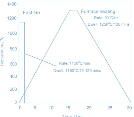
In comparison to traditional furnace heating, fast-firing sintering can considerably reduce the processing time. This rapid processing time offers a number of potential merits including [117]: (i) the establish-ment offine grain sized materials with potentials for improvement in dielectric and mechanical properties; (ii) drastic reduction in the energy consumed by the furnace whilst allowing for continuous processing; (iii) reduction in material loss (e.g. lead oxide which frequently occur in lead-based materials) held at high sintering temperature over long durations.Fig. 6illustrates a huge reduction in processing time when fast-firing sintering is adopted.
Using fast-firing sintering, the density of a number of ceramic ma-terials including lead zirconate titanate (PZT) [117–119], Al2O3[120], BaTiO3 [121], Y2O3-doped ZrO2 [122,123] have been shown to in-crease. For detailed review on fastfiring sintering technique see Klein and Hotza [124] and García et al. [125]. Heidary et al. [90] concluded that in a conventional furnace, the reduction in energy consumption is considerable for a slight increase in heating rate which can be achieved by improving the furnace’s heating power, through the design of im-proved heat transfer strategies, by adopting materials that are more thermally insulative and or heat recovery techniques [126,127].
Despite the advantages offered by fast-firing technique, it suffers from a number of limitations. For instance, the notion of increasing heating rate with the view to enhance densification may not be ap-plicable to all ceramics. An example of such instance was extensively illustrated by Rahaman [128] using MgO powder as a case study given that its∆Hgis between 360 and 450 kJ/mol but the∆Hdis between 150 and 500 kJ/mol, for which the Mg2+diffusion possess the slowest rates. Furthermore, with the sintering front, the heating rate would be con-strained, as described by García et al. [125] who concluded that in-homogeneous densification (i.e. the rise in the amount of pores from the surface toward the inside of the sample) could result if the quantity of heat transfer within the samples is not sufficient to withstand the ad-vancement of the sintering front. As such, fastfiring is appropriate for small parts and/or thin wall sections because the heating rate is further constrained when large parts with intricate geometry are being sintered due to different rate of shrinkage which generates internal strain [90].
2.7. Liquid-phase sintering
Liquid phase sintering (LPS) is a sintering strategy employed for producing high performance, multiphase components from powders [129,130]. It is widely employed to consolidate metallic powders and ceramics intofinal shapes [131]. The technique is simple and effective and has the capability of reducing sintering temperature and by ex-tension energy consumption [90]. It entails sintering under conditions in which solid particles coexist with a wetting liquid (i.e. incorporating a phase into the particles with the aid of low melting temperature) [90,129]. During the process of sintering, the secondary phase melts, enhances flow between the particles whilst facilitating particle re-arrangement and diffusion process [90]. Essentially, during LPS, den-sification is based on rearrangements and change of shape of solid constituents [131]. LPS offers a number of advantages including low sintering temperatures, rapid densification as well as highfinal den-sities yielding microstructures that can provide physical or mechanical materials properties that are higher than solid state sintered materials [131]. For detailed description of the underlying mechanism, modes of operations and potential future research area for advancing the LPS, we refer readers to Kaysser and Petzow [131] and German et al. [129].
Different forms of LPS have been applied to an extensive array of engineering materials including connecting rods in engine of auto-mobiles and high-speed metal cutting inserts [129]. The technique has also been employed in the fabrication of a number of ceramics with the view to lowering the sintering temperature. For instance Kimura et al. [132] demonstrated the relationship between the sintering tempera-tures of BaTiO3powders whilst using concentrated of Li2CO3as a sin-tering aid to reduce sinsin-tering temperature from 1300 °C to 1000 °C. A summary of a number of materials systems for sintering aids employed for the overall lowering of sintering temperature of LPS is provided by Heidary et al. [90] who concluded that none of the materials systems employed decreased the sintering temperature below 900 °C. However, the application of LPS in varistors based on ZnO, where Bi2O3powder with a melting point of 817 °C was employed as a sintering aid for sintering ZnO powders have been reported [90]. Accordingly, Bi2O3 offers advantages in terms of lowering sintering temperature without compromising very good electrical properties [90].
2.8. Cold sintering
[image:9.595.55.275.54.246.2]For reasons discussed above and outlined in refs [16,133], there is still an industrial need to devise novel sintering technology at tem-peratures/energy consumption much lower than currently achievable. Cold sintering allows ceramic particulates to be densified at extremely low temperatures of < 300 °C, whilst maintaining low grain size in comparison to conventional sintering technique for typical oxide ma-terials [15,16,134]. The concept of cold sintering wasfirst introduced by Gutmanas et al. [20,135–138] whereby the temperature at which a particular material is sintered is as low as room temperature with densification induced by plastic flow of the particles at 4 GPa. The concept was adjudged successful when applied to metallic powders and composites including cobalt, aluminium, copper, iron, niobium, tan-talum and some compounds such as CdTe, MgO, NaCl to mention a few [20]. However, the densification process described by Gutmanas et al. [20,135–138] is solely based on plastic deformation under high pres-sure with no interdiffusion, which limits the technique to metal and plastic due to the brittle nature of the ceramics and glass [20,90,139]. Liao et al. [140] reduced the particle size of alumina to 18 nm with the view to increasing deformability and obtained samples > 80% dense at 8 GPa at room temperature followed by a post-press anneal at 460 °C, yielding an improved density of > 98%. This was a significant im-provement in sintering temperature when compared to conventional sintering which normally occurs at ˜1450 °C. As thermodynamically demonstrated by Liao et al. [140], pressure can allow the prevention of grain growth whilst enhancing densification. As such, the combined Fig. 6.Illustration of large reduction in processing time by using the fastfiring
effect of plasticflow and inter-diffusion of particles with an arrested grain growth can lead to development of products with high relative density [90,140].
Densification of ceramics under hydrothermal conditions has also been attempted but did not attract the requisite attention across the entire ceramic community [139]. For example: Roy et al. [141] pro-duced cementitious materials with very high strengths; Hirano and Somiya [142] studied hydrothermal reactions for the densification of basic oxides such as Cr2O3and Anagisawa et al. [143], Yamasaki et al. [144] and Kim et al. [145] have all demonstrated pressing under hy-drothermal conditions for the densification of materials such asfly ash, cement and hydroxyapatite. It is important to note that cold sintering technique differs from hydrothermal synthesis. Hydrothermal synthesis make use of phase reactions for the crystallisation of anhydrous mate-rials from solution under sealed reaction vessels [146–148]. Hydro-thermal hot pressing and reactive hydroHydro-thermal sintering can cause solidification but the product yield are usually porous [146]. However, cold sintering is densification with or without phase reactions as dis-cussed in the succeeding paragraphs [133].
FAST or Flash sintering [96], microwave sintering [24,50], spark plasma sintering [85,149–151], rate-controlled or fast sintering [152], two-step sintering [153] and high-pressure sintering [154] have all thus been utilised in attempts to reduce sintering temperature and conse-quently energy consumption. Combinations of these techniques have also been attempted [155], all of which have made giant strides to-wards attaining lower sintering temperature profile, although the re-duced temperatures are still typically confined to > 400 °C. However, inspired by research conducted at Tokyo Institute of Technology [156] and at the University of Oulu on lithium molybdate ceramics [157], a novel sintering technique [17] has recently emerged capable of densi-fying ceramics at < 300 °C from Randall and co-workers at the Penn-sylvania State University, USA. Termed the Cold Sintering Process (CSP) [27,133] to distinguish it from high pressure sintering, an in-creasing number of ceramics and composites can be fabricated at up to 1000 °C lower than their conventional sintering temperatures.
In CSP, diffusion between particles is improved by adding a tran-sient solvent to the powder and easily obtainable pressures of˜350 MPa are required instead of 8 GPa inpreviosu cold sintered ceramics. CSP provides a new route for ceramic fabrication in several ways: (i) aiding new materials discovery through integration of materials that are nor-mally not co-sintered, such as polymers and metals [16]; (ii) reduction in energy consumption towards attaining a decarbonised ceramic sector; (iii) compatibility with multilayer device fabrication technology such as screen printing and tapecasting and (iv) integration of materials that react chemically, undergo decomposition or exhibit volatile be-haviours [158].
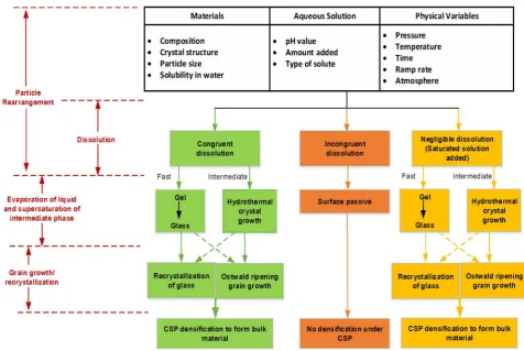
The range of materials/composites that have been successfully fabricated using CSP include nanomaterials, quantum dots, polymers, inorganics, biomaterials, liquid crystals, 2-D materials, Metal-Organic-Frameworks (MOFs) and phosphors [158]. CSP also covers a wide array of chemical variations and crystal structures including binary and quinary compounds such as phosphates, oxides, iodides, fluorides, chlorides and carbonates [158] in applications such as prospective thermoelectrics, microwave dielectrics, Li-cathode materials, ferro-electrics, piezoferro-electrics, semiconductors, metallic oxide conductors, ionic electrolytes, and refractory materials [158]. Specifically, CSP has been demonstrated on BaTiO3[15,159], ZnO [134,139], V2O5, [16,17] ZrO2 [160], Li2MoO4 [18,133], NaNO2, [27] K2Mo2O7, [133] Na2Mo2O7, [133] PZT [161], KH2PO4[27] and many more, whilst at-taining density ranging across 90–98%. CSP can be thought of as a derivative of liquid phase sintering given that both techniques utilises liquid phase to enable mass transfer during sintering. A clear distinction between the two techniques lies in the fact that within a LPS, a molten phase with high temperature enhances the diffusion processes but within CSP, such phases are replaced by a solvent and high pressures [133].Fig. 7depicts the mechanism and possible routes for different
types of materials based on CSP.
CSP involves the following steps [16,27,133]: (i) uniform moist-ening of the ceramic powders with a small quantity of aqueous solution (e.g. water and/or acidic solution). This allows for the decomposition of the solid surface, whilst accelerating the dissolution and transport ki-netics and ensures that a controlled amount of liquid phase is in-tentionally introduced at the particle-particle interface; (ii) within certain temperatures and/or pressure regimes, the solid particles pass through the process of particle re-arrangement with the aid of the aqueous liquid phase followed by densification through dissolution-precipitation. This precipitation emanates from a supersaturated solu-tion that epitaxially grows on the surfaces of the particles. In the so-lution-precipitation process, ionic species and/or atomic clusters transport to the contact to allow for the reduction of local surface curvature of the particle; iii) minimisation of the excess surface free energy and iv) reduction in porosity, yielding materials in dense solid forms [17].
Variables in CSP include particle size, quantity of water addition, pH level and addition of solute, amount of pressure applied, sintering temperature, holding time and heating rates can impact the process of sintering under CSP conditions [133]. Essentially, CSP offers a simple, effective and energy-saving strategy for the fabrication of a number of materials and device development given that it successfully eliminates furnace requirements and high temperatures [90]. The energy con-sumed during CSP can be attributed to (i) the energy required to heat up the dies, evaluated through the monitoring of voltage and current profile during the process; and (ii) energy required for pressing the powders which can be derived by calculating the work done (i.e. the energy expended) by multiplying the force ( )F applied (which is a function of pressure( )P and area( )A of the pellet) by the displacement
d
( )which is the difference in thickness of the pellet before and after the cold sintering process [90].
At the laboratory level, CSP is well-established, however, there are still questions regarding water evaporation processes, densification mechanism and amorphous grain boundaries [90]. There are other challenges of CSP that exist from a scientific and industrial perspective. Specifically an understanding of the dynamic nature of the process is still a challenge with optimisation of grain size and morphology, par-ticle size distribution, die sealing, rate of pressure application, and li-quid phase viscosity required [158]. Most significantly, the transition from laboratory to industry will require a hugely different facilities and infrastructures as compared to conventional sintering [158]. Further-more, statistically relevant property/key performance validation on the industrial side will be required by the ceramic processing community but strategies that involve lower uniaxial pressures and injection moulding would render CSP even more appealing [158].
To compare the energy consumption profile of different sintering techniques, it is important to have a deep understanding of the pro-cesses in terms of how they are governed by mass transfer mechanism. Accordingly, a description of the modelling of energy consumption in parts fabrication via sintering is presented in the next section.
3. Modelling of energy consumption in parts fabrication via sintering
alternative approach is necessary if we are to truly understand the difference between these distinct sintering techniques.
Focusing on cold sintering and the traditional sintering processes as representative examples in this study, we deployed a continuum-level approach, anchored on the concept of transport theorem to: (i) for-mulate the analytical expression relating important variables that
in-fluence the energy consumption pattern of these two types of sintering processes; and (ii) establish a simple process-dependent generalized expression for the energy consumption in these two processes. A cal-culated choice is made to focus the modelling procedure on the tradi-tional sintering technique (being the dominant sintering method) and the cold sintering technique, which has been demonstrated to have a much lower energy consumption profile, in principle. Commentaries on the differences between these two processes have already been explored in earlier studies [133,159]. For the purpose of modelling, we consider two layers to offer a quantitative appraisal of the macroscopic energy-related events in the two sintering processes. In Section3.1, we explore the local energy transport within a minuscule control volume of the two processes, while Section3.2considers the energy consumption at the level of the chamber.
3.1. Analytical model of local energy transport in sintering processes
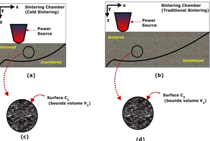
Let us consider the simplified schematics of two chambers for part fabrication by means of cold and the traditional sintering processes shown inFig. 8(a) and (b), respectively. The volume of materials in each chamber is divided into sintered and unsintered regions. With this in mind, we pick an arbitrary small chunk of material and designate this as a control volume. Primarily, the control volume, enclosed by an arbitrary surface boundary shown in each of Fig. 8(a) and (b), sur-rounds a material point in the sintered region. Furthermore, we label, as
revealed inFigs. 8(c) and (d), the size of the control volume asVcsand Vtsfor cold and traditional sintering process, respectively.
At this juncture, it is necessary to highlight a number of points that underpin the following model for the local energy transport:
•
Vcs is from a chamber with a global volumeV1, whileVtsis from a chamber with a global volumeV2;•
Process constrain dictates thatV1(for cold sintering) is always less thanV2(for traditional sintering);•
Both cold sintering and traditional sintering processes are facilitated by particle diffusion, which in turn is aided by heat transfer me-chanism to enable powder sintering;•
Conduction is taken to be the dominant heat transfer mechanism within the volume being sintered. This rests on the fact that heat conduction supersedes thermal loss or gain by surface transfer through convection.Further to the above, it is noted that notwithstanding the type of the sintering process, the heat transfer analysis of each of the two control volume stipulates the satisfaction of this energy balance:
+ = +
E˙inf E˙gen E˙out E˙cin (1)
whereE˙inf andE˙outrefer to the rate of energyflow into and out of the
control volume, whileE˙gen andE˙cin symbolize the rate of generated energy (mostly by internal sources) and rate of change of internal en-ergy of the control volume, respectively.
[image:11.595.56.533.69.388.2]the process generates a volume density of heat energyutransported through the control volumeVcs and endowed with a heatflux density
q x( , ). Clearly, the amount of heat energy int Vcs, denoted asU t( ), can be estimated as:
∫
= x
U t( ) u( , )t dV
V cs (2)
The time rate of change of the heat energyU t( ), at a specific spatial position x, is thus:
∫
∫
= x = x
dU dt
d
dt u t dV
du t
dt dV
( , ) ( , )
V cs V cs (3)
The confluence of the principle of energy conservation and the balance law stated in Eq.(1), necessitates that the time rate of change of U t( ) be equated to the addition of the amount offlux through the surface boundaryC1 (surface of the control volumeVcs as shown in Fig. 8c) and the generation of heat inVcs(by a sourceQ). Consequently, we have:
∫
∫
= − q n +
dU
dt S . dC1 VQ dVcs (4)
wheren denotes an outward normal of unit length contributing to the outwardflux through surfaceC1. To harmonize the integration opera-tions, thefirst integral in Eq.(4)is transformed using the Gauss the-orem, leading to:
∫
∫
= − ∇ q +
dU
dt V . dV VQ dVcs (5)
We re-write Eq.(5), bearing in mind Eq.(3), as:
∫
⎡⎣ + ∇ q− ⎤⎦ =
du
dt . Q dV 0
V cs (6)
At this point, we take the amount of heat to be a function of tem-perature, and as earlier stated we have adopted the Eulerian framework (where the control volume isfixed). Therefore, u=u T t( , ) and one may then transform Eq.(6)as:
∫
⎡ ⎣∂
∂ + ∇ q− ⎤⎦ =
du dT
T
t . Q dV 0
V cs (7)
If the control volume is held constant, the derivative of heat with temperature (du dT/ ) amounts to specific heat at constant volume (cv), a
well-known thermodynamic material property [164]. Further, in one-dimension, ∇.q=∂∂q
z z
. Thus:
∫
⎡ ⎣⎢∂ ∂ +
∂
∂ − ⎤⎦⎥ =
c T
t q
z Q dV 0
V v
z
cs
(8)
The arbitrariness of the control volume allows:
⎡ ⎣⎢
∂ ∂ +
∂
∂ − ⎤⎦⎥ =
c T
t q
z Q 0
v z
cs (9)
A relation between the heatflux and temperature is provided by the simplified one-dimensional Fourier’s law for conductive heat flow (i.e.qz= −kdT dz/ ) [165]. With this, the differential equation gov-erning the local energy transport within the control volume is obtained as:
∂
∂ − ∂∂ ⎛⎝ ⎞⎠=
c T
t z k
dT
dz Q
_ h
(10)
wherekis the axial thermal conductivity (W mK/ ). A closer examina-tion of Eq.(10)shows that it has afirst-order time derivative (which requires a single initial condition) and a second-order spatial derivative (which demands two essential boundary conditions). The solution of Eq.(10)therefore requires the following initial and boundary condi-tions:
= = − ∂ ∂ = =
T z z T k T
z q
( ¯, 0) ¯; ¯
z 0 (11)
whereT¯andq¯are the specified temperature (ambient temperature, for instance) and heatflux, respectively.
[image:12.595.121.478.54.293.2] [image:12.595.310.556.327.425.2]when compared with the conventional sintering process. This latter point enables the cold sintering process to offer a non-negligible gain in energy efficiency [16,133]. To put things in perspectives,q¯is theflux boundary condition, which is governed by the specific thermal power of the radiating power source.
Now, assuming the sintering process is a laser-based process, then the heatflux immediately below the laser source will be a function of the laser power, spot diameter of the laser beam and the scanning speed
v
( ). However, at some distance away from the source, the boundary condition is governed by the Newton’s law of cooling. For the tradi-tional sintering process, the Newton’s law of cooling will be:
− ∂
∂ = = −
k T
z z h [T T ]
tsp surf air
0 (12)
wherehtsp, TsurfandTairare the convective heat transfer coefficient, air-solid interface temperature, and ambient air temperature respectively. Meanwhile, since the cold sintering process is aided by a transientfluid which is different from air, its corresponding Newton’s law of cooling will be:
− ∂
∂ = = −
k T
z|z 0 hcsp[Tsurf Tsolv] (13)
wherehcsp, Tsurf andTsolvare respectively, the cold sintering convective heat transfer coefficient, the interface temperature between the cold sintering transient solvent and the sintered solid, and the temperature of the transient solvent, deployed to assist diffusion growth in the cold sintering process. In a hydrothermal-assisted cold sintering, for in-stance, the process makes use of water as the transientfluid [15]. The convective heat transfer coefficient of water is almost50times that of air [166]. Therefore, the magnitude of the heatflux, and hence power consumption, is less in the cold sintering process.
3.2. Effect of production yield and sintering chamber size on energy consumption
In Section3.1, the quantitative information about the energy con-sumption was based on the consideration of a control volume within the chamber. As such, the mathematical model was derived without a discussion of the effect of chamber size and production yield on the rate of heat generation. In this section, these two factors are considered and we reveal howV1andV2(volume of sintering chambers) are related.
LetQ˙gcsandQ˙gtspbe the time rate of heat generated internally perV1 and V2, respectively. Then:
= =
dQ
dt q V
dQ
dt q V
˙ ; ˙ gcs gV
1 2 2 (13a, b)
whereq˙is the rate of heat generated in durationdtper unit volume. The amount of thermal energy generated( )Q can thus be obtained as:
∫
∫
= =
Qgcs q V dt Q˙ ; q V dt˙
t t gtsp t t 1 2 1 2 1 2 (14a, b)
whereq˙is equivalent to thermal power generated per unit volume (Pg), therefore, a generic expression for heat generated within each sintering chamber takes the form:
= −
Q P V tg (2 t1) (15)
Applying Eq.(15)to each of the sintering process, one obtains:
= =
Q P V τ P m
ρ τ gcs gcs cs gcs
f cs 1
(16)
= =
Q P V τ P m
ρ τ gtsp gtsp tsp gtsp
f tsp 2
(17)
whereρ m, f andτcsdenote density, total mass of the feedstock material being sintered and the duration of the sintering process. Now, since the sintering process may be such that only a fractional massmycan be processed at a time, as is true for the cold sintering process which
requires multiple sintering runs, then it is convenient to normalize the energy terms. Consequently, for further simplifications, we introduce a unifying term called specific power consumption (κ), where κ=P ρg/ , and having a unit ofW Kg/ , and then re-format Eqs.(16)and(17)in terms of energy per kilogramQ˜gcsandQ˜gtspfor the cold and traditional sintering process:
=
Q κ τ m
m ˜gcs cs cs f
y (18)
=
Q κ τ m
m ˜gtsp tsp tsp f
y (19)
In instances where the processing of a given material using cold sintering requires further processing known as annealing as in the case of materials such as PZT and BaTiO3, Eq.(18)can be expanded upon as follows:
= +
Q κ τ m
m κ τ
m m ˜total cs cs f
y a a
f
y (20)
where on the one handQ˜totalis the normalized total consumed energy in Joule/kg, whileκ τa arepresents the specific power consumption in the duration of the annealing process.
3.3. Understanding the competitive edge of cold sintering beyond laboratory conditions
As highlighted in Section 2.8, cold sintering process offers tre-mendous energy saving potential compared to other well-established sintering techniques for ceramic processing. For instance, Heidary et al. [90] reported that the thermal energy consumed due to the sintering of BaTiO3 powder can significantly reduce from 2800 kJ/g using con-ventional sintering, to 2000 kJ/g based on liquid phase sintering, 1050 kJ/g using FAST sintering, 540 kJ/g with microwave sintering, through to 130 kJ/g for fast-firing, to a very low thermal energy of 30 kJ/g for the CSP. Afigure of merit termed“Normalized Excess En-ergy”, was adopted by the authors as afirst order approximation for the comparison of the energy savings potential of various to sintering techniques. On a gram by gram basis under laboratory conditions, the submissions by the authors in terms of the superiority of cold sintering process over other types of sintering techniques is valid. However, if the process is scaled up to sinter higher quantities of ceramic materials, there is a cross-over point during which the competitive edge of cold sintering process may become diminished.
To drive home the point, an example based on comparison between energy consumption during cold sintering process (CSP) and conven-tional/traditional sintering (TSP) of ZnO is used. Assuming 1 kg of ZnO was sintered using CSP and TSP based on the following scenario in the laboratory. CSP: 100 g (equivalent to 1 press) of ZnO was sintered 2 h at 120 °C, resulting in 10 parts for the 1000 g, using sintering equipment with a power rating of 1.8 kW; TSP: 100 g of ZnO pressed for 2 min with an equipment of power rating 1.8 kW and then sintered at 1400 °C for 7 h, yielding 10 cycles for the 1000 g (i.e. 10 parts for the 1 kg), power rating of equipment is 5.5 kW. Based on this laboratory sintering sce-nario, CSP consumes 12.96 MJ (3.6 kW h) per press, resulting in 36 kW h for the entire 10 presses. On the other hand, TSP consumes 0.216 MJ (0.06 kW h) per pressing plus 138.6 MJ (38.5 kWh) during sintering. For 10 presses, the total energy consumed is
× + = kWh
((0.06 10)) 38.5) 39.1 , which is slightly higher than the energy consumed for CSP, demonstrating its edge over TSP.
However, it is immediately clear that from a purely energy con-sumption perspective, there cross-over point during which the ad-vantages of CSP may become diminished compared to TSP as depicted schematically inFig. 9. So the key question is‘where does this cross over point lie based on the laboratory scenario described above’? This point can be established by finding the point of equilibrium when
=
Qcsp Qtsp. For simplicity sake, letQcsp=3.6×

![Fig. 2. Distribution of energy cost by industry in Japan [13].](https://thumb-us.123doks.com/thumbv2/123dok_us/1858799.142675/4.595.141.460.476.729/fig-distribution-energy-cost-industry-japan.webp)
![Fig. 5. Basic configuration of SPS illustrating a die set mounted and exposed toa mechanical load and electrical current, adapted from Gaultois [69].](https://thumb-us.123doks.com/thumbv2/123dok_us/1858799.142675/7.595.54.272.55.199/conguration-illustrating-exposed-mechanical-electrical-current-adapted-gaultois.webp)

![Fig. 11. Ranking of negative cost measure using Pareto optimisation. Adaptedfrom Taylor [171].](https://thumb-us.123doks.com/thumbv2/123dok_us/1858799.142675/16.595.70.252.57.236/ranking-negative-measure-using-pareto-optimisation-adaptedfrom-taylor.webp)