This is a repository copy of
Higher order mode circularly polarized two-layer rectangular
dielectric resonator antenna
.
White Rose Research Online URL for this paper:
http://eprints.whiterose.ac.uk/130521/
Version: Accepted Version
Article:
Abdulmajid, A.A., Khalil, Y. and Khamas, S.K. orcid.org/0000-0001-9488-4107 (2018)
Higher order mode circularly polarized two-layer rectangular dielectric resonator antenna.
IEEE Antennas and Wireless Propagation Letters. ISSN 1536-1225
https://doi.org/10.1109/LAWP.2018.2834981
© 2018 IEEE. This is an author produced version of a paper subsequently published in
IEEE Antennas and Wireless Propagation Letters. Uploaded in accordance with the
publisher's self-archiving policy. Personal use of this material is permitted. Permission from
IEEE must be obtained for all other uses, in any current or future media, including
reprinting/republishing this material for advertising or promotional purposes, creating new
collective works, for resale or redistribution to servers or lists, or reuse of any copyrighted
component of this work in other works
eprints@whiterose.ac.uk
https://eprints.whiterose.ac.uk/
Reuse
Items deposited in White Rose Research Online are protected by copyright, with all rights reserved unless
indicated otherwise. They may be downloaded and/or printed for private study, or other acts as permitted by
national copyright laws. The publisher or other rights holders may allow further reproduction and re-use of
the full text version. This is indicated by the licence information on the White Rose Research Online record
for the item.
Takedown
If you consider content in White Rose Research Online to be in breach of UK law, please notify us by
Higher Order Mode Circularly Polarized Two-Layer Rectangular
Dielectric Resonator Antenna
Abdulmajid A. Abdulmajid, Yas Khalil, and Salam Khamas
Abstract— A two-layer higher order mode circularly polarized (CP) rectangular dielectric resonator antenna (RDRA) is proposed at a frequency range of 10 to 13GHz using a single-feed. The configuration incorporates the DRA and a dielectric coat layer with respective dielectric constants of 10 and 3.5. Utilizing the outer layer offers a number of advantages such as wider impedance and CP bandwidths of ∼21%, and 9.5%, respectively, as well as a high gain of ~11dBic. Close agreement has been achieved between experimental and simulated results.
Index Terms—Dielectric resonator antenna, circular polarization, high
order mode, 3D printing.
I. INTRODUCTION
The last few decades have witnessed a considerable growth in wireless communication systems, with a particular attention being given to high frequency ranges such as the X- and mm-wave bands. Owing to their attractive radiation characteristics such as high radiation efficiencies and wider bandwidths, DRAs are more favorable for high frequency applications [1-5]. In addition, DRA excitation at higher frequencies can be achieved by employing a slot aperture coupling that has been demonstrated experimentally for the first time in [6]. In order to maintain practical antenna dimensions and increase the gain, higher order mode DRAs need to be considered at higher frequencies. The earlier studies on higher order mode DRAs have been mainly focused on linearly polarized radiation [7-9]. On the other hand, circularly polarized DRAs’ radiation is less influenced by atmosphere conditions and insensitive to the transmitter and receiver orientations. As a result, singly-fed CP DRAs that operate at lower order modes have been reported in numerous studies with novel approaches such as employing a rotated slot-fed RDRA [10], or proposing a properly engineered DRA geometry with a wide axial ratio (AR) bandwidth of ~9% [11]. Therefore, higher order modes CP DRAs have received increased interest recently. For example, a higher order mode dual-band CP chamfered RDRA has been reported using a single feed point [12]. The dual bands have been achieved by exciting the TE111 and TE113
resonance modes with respective impedance and axial ratio bandwidths of 11.4% and 1.4% as well as a gain of ~7dBic for the TE113 mode. In addition, a quadrature-fed CP RDRA has been
proposed in [13] by exciting the TE111 and TE113 resonance modes
with a maximum gain of 6dBic. In a recent study, a cross slot-fed dual band CP DRA that operates in the TE111 and TE113 higher order
mode has been presented with respective impedance and AR bandwidths of 8.4 % and 2.2% and a gain of ∼4.3dBic for the TE113
mode [14]. Therefore, TE113 representsthe highest mode order that
has been considered for a CP DRA. It is well known that increasing the mode order results in a considerably higher gain [7, 9], which represents a key requirement at higher frequency applications. However, higher order modes are usually associated with a narrower bandwidth, which can be attributed to the fact that the DRA effective dielectric constant increases with the mode order [8]. A well-known technique to improve the bandwidth is the incorporation of a dielectric coat in the configuration, which has been demonstrated for linearly polarised cylindrical and hemispherical lower order mode DRAs [15-18]. However, the impact of the dielectric coat on the
performance of higher order modes and/or circularly polarized DRAs has not been considered earlier. In this letter, a CP DRA that operates in the TE11,11 higher order mode is proposed, where the
aforementioned narrow bandwidth issue has been addressed by coating the DRA with a dielectric layer. The presented results demonstrate that combining
(a)
[image:2.595.309.546.270.547.2](b)
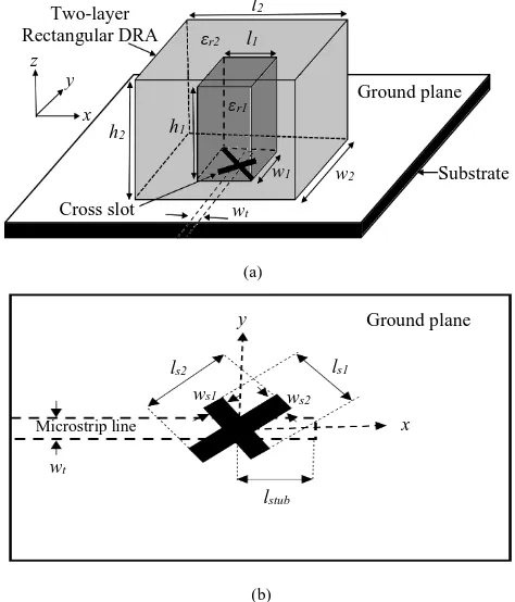
Fig. 1. Geometry of the configuration (a) Layered rectangular DRA (b) Top view of the feed network.
Fig. 2. The outer dielectric coat and the rectangular DRA before and after assembly.
l2
l1
εr1 εr2
w1 h1
y
w2 x
h2 z
Two-layer Rectangular DRA
Ground plane
Substrate
wt
Cross slot
Microstrip line
Ground plane
lstub
x y
ws2 ws1
ls2 ls1
[image:2.595.311.542.579.729.2]DRA that operates in a higher-order mode, outer dielectric layer and cross slot excitation presents a novel approach for generating wider impedance and CP bandwidths of ∼21%, and 9.5%, respectively, together with an enhanced gain of ~11dBic.The simulations have been conducted using CST microwave studio [19]. A prototype of the layered higher order mode DRA has been built and measured with close agreement between experimental and simulated results.
I. ANTENNA CONFIGURATION
Figure 1 illustrates the proposed layered RDRA configuration and feed network, where a cross slot has been employed to excite the antenna [20, 21]. The DRA has been fabricated using Alumina with a dielectric constant of 10 and a loss tangent of tanδ<0.002. Two
configurations have been considered that utilize the same DRA element without, and with, a dielectric coat. The DRA dimensions have been chosen as l1=w1=4 mm and h1=40 mm. Further, the outer
layer has been fabricated using a 3D printed Polyimide layer with a dielectric constant of 3.5 and dimensions of l2=w2=20 mm and h2=41
mm. A central rectangular air-gap has been created in the Polyimide dielectric coat to accommodate the DRA as illustrated in Figure 2. Once the coat is fabricated, the DRA has been inserted in the central air-gap and a dielectric powder has been utilized to fill any gaps between the DRA and the coat.
A 50Ω microstrip-feed line has been etched on a Rogers RO4535 substrate with a dielectric constant of 3.48 and a loss tangent of 0.0037. The respective length, width, and thickness of the substrate are 150mm, 100mm, and 0.8mm. Furthermore, in order to excite the CP RDRA two slots have been itched on the copper ground plane. Each slot is tilted by an angle of 45⁰ with respect to the microstrip line that has been printed on the backside of the substrate. Additionally, unequal slot lengths have been chosen in order to excite two near-degenerate orthogonal modes of equal amplitude and 900 phase difference that are needed to generate the CP radiation
[20]. The coupling cross slot element lengths have the same width of
ws1 = ws2=1mm and unequal lengths of ls1=4.4mm and ls2=5mm. In
addition, an open stub length of lstub=2.5mm has been utilized for
optimum matching. Furthermore, a double sided adhesive copper tape has been employed to eliminate the potential air-gaps between the DRA and ground plane [22] . The reflection coefficient has been measured using an E5071C vector network analyzer, whereas the radiation patterns and gain have been measured using an NSI system.
III. RESULTS
A. Single Layer Higher Order Mode CP RDRA
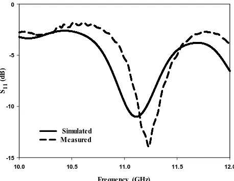
A rectangular DRA prototype has been fabricated with dimensions that supports the TE117 mode at 11.1GHz. The simulated and
measured reflection coefficients are presented in Figure 3, with respective impedance bandwidths of 1.9% and 1.78%. The measured resonance frequency is 11.2GHz, which agrees well with the simulated counterpart. The broadside gain and AR are depicted in Figure 4 with measured and simulated gains of ∼7.5dBic at 11.2GHz. The simulated CP operation bandwidth extends from 11.1 to 11.37GHz, which corresponds to a 3dB AR bandwidth of 2.4% that agrees well with a measured AR bandwidth of 2.3% over a frequency range of 11.1 to 11.4GHz.
B. Two-layer Higher Order Mode CP RDRA
Incorporating a dielectric coating layer, with a relative permittivity of εr2, creates a transition region between the DRA and free space,
Frequency (GHz)
10.0 10.5 11.0 11.5 12.0
[image:3.595.311.540.98.275.2]S1 1 ( d B ) -15 -10 -5 0 Simulated Measured
Fig. 3. Reflection coefficient of a single layer RDRA operating in the TE117.
mode
Frequency (GHz)
10.0 10.5 11.0 11.5 12.0
[image:3.595.310.541.105.468.2]A x ia l R a ti o (d B ) 0 1 2 3 4 5 6 7 8 9 10 G a in (d Bic ) 0 1 2 3 4 5 6 7 8 9 10 Simulated Measured AR Gain
Fig. 4. Gain and the axial ratio of a single layer higher order mode DRA.
which improves the impedance bandwidth considerably [2]. The DRA inner magnetic field distribution can be represented as an array of short magnetic dipoles, in which a maximum gain can be accomplished when the separation distance between the adjacent magnetic dipoles is ~0.4λo, where λo is the free space wavelength
[7]. In addition, when the DRA is surrounded by another dielectric medium, the maximum gain can be achieved when the adjacent magnetic dipoles are separated by a distance of ~0.4λg,
whereλg =λ0 εr2, which results in a lower profile and a more
practical configuration. Therefore, a prototype of a two-layer DRA has been fabricated and measured in order to demonstrate the potential of such antenna.
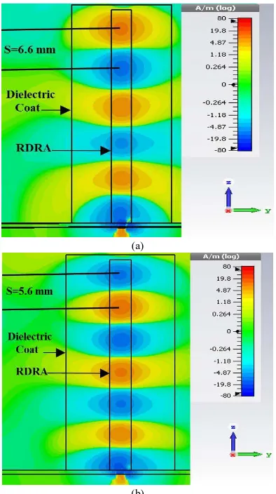
The magnetic field distribution inside the DRA is illustrated in Figure 5, where it can be observed that the separation distance between adjacent short magnetic dipoles, S, for the TE11,11 mode is
6.6mm at 11.3GHz, which exceeds 0.44λg. Therefore, a higher gain
of 11.1dBic has been achieved at this frequency point. Similarly, it can be noted that for the TE11,13 mode, the separation distance is
5.6mm, which corresponds to less than ~0.4λg at 12GHz, hence a
[image:3.595.316.538.297.474.2]significant bandwidth enhancement compared to that of a single layer DRA. In addition, it is evident from these results that the layered DRA supports a multi-mode operation where the TE11,11 and
TE11,13 modes have been excited at 11.3 and 12GHz, respectively,
which also contributes to the bandwidth enhancement.
(a)
[image:4.595.319.551.98.386.2](b)
Fig. 5 Magnetic field distribution inside the layered DRA that operates in
the (a) TE11,11 at 11.3GHz and (b) TE11,13 at 12GHz resonance modes.
Frequency (GHz)
9 10 11 12 13
S1
1
(d
B
)
-30 -20 -10 0
Simulated measured TE119
TE11,11
TE11,13
Fig. 6 Reflection coefficient of a layered RDRA operating in multi-higher order modes.
(a)
(b)
Fig. 7 Radiation patterns of a layered DRA excited in the TE11,11 mode at
11.3GHz a) φ=0 b) φ=90.
Frequency (GHz)
9 10 11 12 13
G
a
in
(d
B ic
)
0 2 4 6 8 10 12
[image:4.595.76.273.156.508.2]Simulated Measured
Fig. 8 Gain for a higher order mode layered RDRA.
Figure 7 illustrates a reasonable agreement between the measured and simulated radiation patterns of the layered DRA at 11.3GHz, where it can be noticed that a left hand CP radiation has been achieved since EL is greater than ER by 15dB. The measured and
[image:4.595.316.536.403.601.2] [image:4.595.57.290.546.737.2]Frequency (GHz)
10.0 10.5 11.0 11.5 12.0
A
x
ia
l
R
a
ti
o
(d
B
)
0 1 2 3 4 5 6
[image:5.595.56.317.95.280.2]Simulated Measured
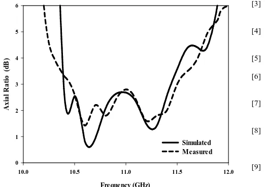
Fig. 9 Axial ratio of a higher order mode layered RDRA.
which may contributes to this discrepancy. The simulated and measured axial ratio of the layered DRA are depicted in Figure 9, where it can be observed that a CP radiation has been achieved over a frequency range of 10.4 to 11.44GHz, which corresponds to a 3dB AR bandwidth of 9.5% compared to a measured counterpart of 9.1%. It is worth mentioning that the length of the slots have been altered slightly to ls1=4 mm and ls2=5.6 mm in order to achieve a wider CP
bandwidth.
V. CONCLUSIONS
A singly fed higher order mode CP RDRA have been considered theoretically and experimentally, where a dielectric coat has been incorporated in the configuration. As expected, the inclusion of a dielectric coat increases the impedance bandwidth considerably. This is combined with a significant enhancement in the far field characteristics such as AR bandwidth and gain. For example, a two-layer RDRA operating in the TE11,11 mode offers respective impedance
and 3dB AR bandwidths of ∼21% and 9.5%. Additionally, the TE11,11
mode provided a higher gain of 11.1dBic compared to 7.5dBic for the single layer DRA operating in the TE117 mode, which also offers
narrower impedance and AR bandwidths. Furthermore, the presence of the second dielectric layer improves the mechanical robustness of the configuration since a long and thin ceramic DRA can be fragile. In addition, a close agreement has been achieved between the measured and simulated results. Although the DRA has been designed at the X frequency band, the demonstrated high gain and wide bandwidths represent appealing radiation characteristics for applications in the mm-wave and terahertz higher frequency bands.
ACKNOWLEDGMENT
The authors would like to thank Dr. Candice Majewski and Ms. Wendy Birtwistle at the Centre of Advanced Additive Manufacturing (AdAM), University of Sheffield, for granting access to their facilities and their technical assistance with the laser sintering process.
REFERENCES
[1] A. Petosa, A. Ittipiboon, Y. Antar, D. Roscoe, and M. Cuhaci,
"Recent advances in dielectric-resonator antenna technology,"
IEEE Antennas Propagat. Mag., vol. 40, pp. 35-48, 1998.
[2] K. M. Luk, K. W. Leung, K. Luk, and K. Leung, "Dielectric
resonator antennas," 2002.
[3] L. Z. Thamae and Z. Wu, "Broadband bowtie dielectric resonator
antenna," IEEE Trans. Antennas Propagat., vol. 58, pp. 3707-3710, 2010.
[4] G. Makwana and D. Ghodgaonkar, "Wideband stacked
rectangular dielectric resonator antenna at 5.2GHz," Int. J. of
Electromagnetics and Applications, vol. 2, pp. 41-45, 2012.
[5] R. W. Heath Jr, R. C. Daniels, and J. N. Murdock, Millimeter
wave wireless communications: Pearson Education, 2014.
[6] J. S. Martin, Y. Antar, A. Kishk, A. Ittipiboon, and M. Cuhaci,
"Dielectric resonator antenna using aperture coupling," Elec. Lett., vol. 26, pp. 2015-2016, 1990.
[7] A. Petosa Petosa and S. Thirakoune, "Rectangular dielectric
resonator antennas with enhanced gain," IEEE Trans. Antennas
Propag., vol. 59, pp. 1385-1389, 2011.
[8] Y. M. Pan, K. W. Leung, and K.-M. Luk, "Design of the
millimeter-wave rectangular dielectric resonator antenna using a higher-order mode," IEEE Trans. Antennas Propag., vol. 59, pp. 2780-2788, 2011.
[9] S. Maity and B. Gupta, "Closed Form Expressions to Find
Radiation Patterns of Rectangular Dielectric Resonator Antennas for Various Modes," IEEE Trans. Antennas Propag., vol. 62, pp. 6524-6527, 2014.
[10] M. B. Oliver, Y. M. M. Antar, R. K. Mongia, and A. Ittipiboon,
“Circularly polarized rectangular dielectric resonator antenna,” Elec. Lett., vol. 31, pp. 418–419, Mar. 16, 1995.
[11] L. Chu, D. Guha, and Y. Antar, "Comb-shaped circularly
polarised dielectric resonator antenna," Elec. Lett., vol. 42, pp. 785-787, 2006.
[12] H. San Ngan, X. S. Fang, and K. W. Leung, "Design of dual-band
circularly polarized dielectric resonator antenna using a higher-order mode," IEEE-APS Topical Conference on Antennas and
Propag. in Wireless Comm., pp. 424-427, 2012.
[13] B. Li, C.-X. Hao, and X.-Q. Sheng, "A dual-mode quadrature-fed
wideband circularly polarized dielectric resonator antenna," IEEE ntennas and wireless propagat. lett., vol. 8, pp. 1036-1038,2009.
[14] X.-C. Wang, L. Sun, X.-L. Lu, S. Liang, and W.-Z. Lu,
"Single-feed dual-band circularly polarized dielectric resonator antenna for CNSS applications," IEEE Trans. Antennas Propagat., Vol. 65 ,
pp. 4283 - 4287 ,2017.
[15] K. W. Leung and K. K. So, "Theory and experiment of the
wideband two-layer hemispherical dielectric resonator antenna," IEEE Transact. Antennas Propagat., vol. 57, pp. 1280-1284, 2009.
[16] R. K. Chaudhary, K. V. Srivastava, and A. Biswas, "Two-layer
embedded half-split cylindrical dielectric resonator antenna for wideband applications," 9th European Radar Conference
(EuRAD), pp. 489-491, 2012.
[17] X. S. Fang and K. W. Leung, "Design of wideband
omnidirectional two-layer transparent hemispherical dielectric resonator antenna," IEEE Trans. Antennas Propagat., vol. 62, pp. 5353-5357, 2014.
[18] Y. Sun, X. Fang, and K. W. Leung, "Wideband two-layer
transparent cylindrical dielectric resonator antenna used as a light cover," IEEE Int. Conf. on Computational Electromagnetics, pp. 286-287, 2015.
[19] CST Reference Manual. Darmstadt, Germany, Computer
Simulation Technology, 2017.
[20] R. D. Maknikar and V. G. Kasabegoudar, "Circularly polarized
cross-slot-coupled stacked dielectric resonator antenna for wireless applications," Int. Journal of Wireless Comm. and Mobile
Computing, vol. 1, pp. 68-73, 2013.
[21] G. Almpanis, C. Fumeaux, and R. Vahldieck, "Offset
cross-slot-coupled dielectric resonator antenna for circular polarization,"
IEEE Microwave and Wireless Comp. Lett., vol. 16, pp. 461-463,
2006.
[22] K. W. Leung, "Conformal strip excitation of dielectric resonator