Int. J. Electrochem. Sci., 10 (2015) 4812 - 4819
International Journal of
ELECTROCHEMICAL
SCIENCE
www.electrochemsci.org
Effects of Magnetic Fields on the Electrodeposition Process of
Cobalt
Yundan Yu1,*, Zhenlun Song1, Hongliang Ge1, Guoying Wei2, Li Jiang2 1
Ningbo Institute of Materials Technology and Engineering, Chinese Academy of Sciences, Ningbo 315201, Zhejiang, China
2
College of Materials Science and Engineering,China Jiliang University *
E-mail: [email protected]
Received: 7 March 2015 / Accepted: 29 March 2015 / Published: 28 April 2015
Magnetic fields parallel to electric fields were applied in the experiment to prepare cobalt thin films from the electrolyte without chemical additives. Influences of various magnetic intensities on the electrochemistry process, deposition mass and surface morphology were studied. According to the experiment, steady state current and deposition mass decreased gradually with the increase of magnetic intensities. The result of electrochemical impedance showed that transfer resistance increased with the magnetic intensity ranged from 0 to 1 T. During the electrodeposition process, cobalt near cathode is lower than other places in the solution. A gradient in the concentration of paramagnetic cobalt ions leads to a gradient in the magnetic susceptibility which would induce to a magnetic driving force when the magnetic field was applied. This magnetic driving force would push the cobalt ions away from cathode to hinder cobalt deposition resulting in decrease of steady state current and transfer resistance. The cobalt films are composed of typical nodular structures. However, hill-like structures could be observed with the increase of magnetic intensity. Cobalt grains tend to grow perpendicularly to the substrate with the condition of higher magnetic intensity due to the ferromagnetic property of cobalt atoms.
Keywords: Magnetic field; Cobalt thin films; Electrodeposition
1. INTRODUCTION
storage devices. Especially, with the development of micromechanical systems, it is essential and indispensable to produce small and thin cobalt magnetic films with high quality.[3-5] Many ways could be utilized to prepare cobalt thin films, such as electrodeposition, sputtering, vapor deposition and so on. Meanwhile, electrodeposition is an simple way to obtain cobalt thin films. However, a new method, magnetic electrodeposition, was chosen to prepare cobalt films in the paper. It is established that magnetic fields would affect electrochemical process and structure of electrodeposited films which may influence their physical properties. It is important to analyze field forces during magnetic electrodeposition process. Lorentz forces and magnetic driving forces are two significant forces need to be clear. Lorentz force is induced with the interaction between electric field and magnetic field, which could cause magnetohydrodynamic (MHD) phenomenon to disturb electrode surface during the magnetic electrodepostion process.[6-7] Magnetic driving forces occur if a gradient in the concentration of paramagnetic ions leads to a gradient. When the magnetic field is vertical to the electric field, Lorentz force is dominated. However, if the magnetic field is parallel to electric field during magnetic electrodeposition process, magnetic driving force is dominated.[8-9] Effects of vertical magnetic fields on electrodeposition process have been investigated by our group.[10-12] Hence, magnetic fields parallel to the electric fields were introduced in the paper to investigate their effects on electrochemistry process of cobalt electrodeposition.
2. EXPERIMENTAL PART
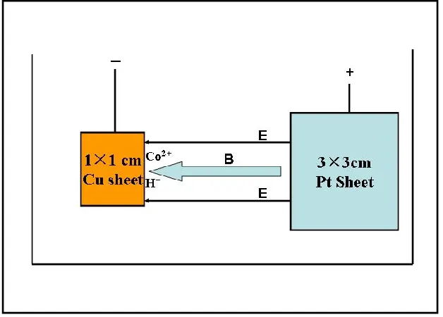
The magnetic fields parallel to the electric fields were applied in the experiment to prepare cobalt thin films on copper sheets. Effects of magnetic intensities on the cyclic voltammetry process, surface morphology and mass transfer process of the films were investigated. Fig.1 below shows chart of parallel magnetic fields model in the experiment.
[image:2.596.150.464.502.727.2]
The electrolyte was composed of 0.01 M CoSO4 and 0.1 M NaCl without additives. Copper sheet with 1×1 cm2 was working electrode while Pt sheet with 3×3 cm2 was chosen as the counter electrode. Saturated Calomel Electrode was used as the reference electrode in the cobalt electrodeposition system. The copper sheet was immerged into 100 ml plating bath to perform cobalt electrodeposition for 20 minutes with the magnetic field parallel to electric field. Cyclic voltammetry method was used to investigate electrochemistry process of cobalt electrodepsotion. The scan rate was ranged from 10 to 30 mv/s with the scan voltages between 0.4 VSCE to -1.6 VSCE. Transient curves with various magnetic intensities (0-1 T) at -1.2 VSCE were chosen to study effects of magnetic intensity on current density. Mass changing of cobalt films prepared with different magnetic intensities was studied by Quartzmicrobalance (QCM25). The Quartzmicrobalance is an extremely sensitive sensor capable of measuring mass changes in μg/cm2. Sauerbrey equation[13] was used in the paper to calculate the mass change in the magnetic plating process for cobalt films.
m C f f
Equation (1)
Where, f is the observed frequency change in Hz, m is the change in mass per unit area (μg /cm2), and Cf is the sensitivity factor for crystal (56.6 Hz cm2/μg). During the plating process, concentration of cobalt near cathode is lower than other places in the solution. A gradient in the concentration of paramagnetic cobalt ions leads to a gradient in the magnetic susceptibility which would induce to a magnetic driving force in magnetic field.[14-15] .The magnetic driving force could be expressed by the equation below:
c B Fp m
0 2
2
Equation (2)
Where c is the concentration gradient, m is the molar susceptibility of the ions, 0 is the permeability of free space. Diamagnetic and paramagnetic ions would move in the opposite direction with the magnetic driving force.
3. RESULTS AND DISCUSSION
3.1 Electrochemical process of cobalt without magnetic field
[image:3.596.95.503.555.730.2]
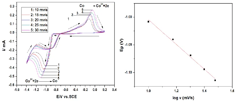
Before discussing the magnetic plating process of cobalt, it is significant to investigate the electrochemical process of cobalt without magnetic field and ensure the electrodeposition model. Cyclic voltammetry process of cobalt electrodepsotion without magnetic fields was shown in figure 2.
According Fig.2, it is clear that the reduction and oxidization process of cobalt are observed at -1.1 VSCE and -0.1 VSCE respectively. Moreover, with the increase of scan rates, the reduction peaks move to more negative positions and peak currents increase accordingly. Different values of reduction and oxidization peaks mean that cobalt electrodepositon process is irreversible. The relationship of log v and Ep is linear which proves that cobalt deposition is controlled by diffusion process. Caina Su[16] reported cobalt deposition mechanism from ionic liquid by cyclic voltammetry analysis. He pointed out that cobalt deposition was a typical kind of diffusion-limited process which was coincide to our conclusion. Concentration gradient is easily formed during electrodeposition based on diffusion controlling. Therefore, cobalt near cathode is lower than other places in the solution during cobalt electrodeposition process. A gradient in the concentration of paramagnetic cobalt ions leads to a gradient in the magnetic susceptibility which would induce to a magnetic driving force if the magnetic field was applied. Detail information about magnetic driving forces was investigated by Reilly.[17]
3.2 Electrochemical process of cobalt with magnetic field
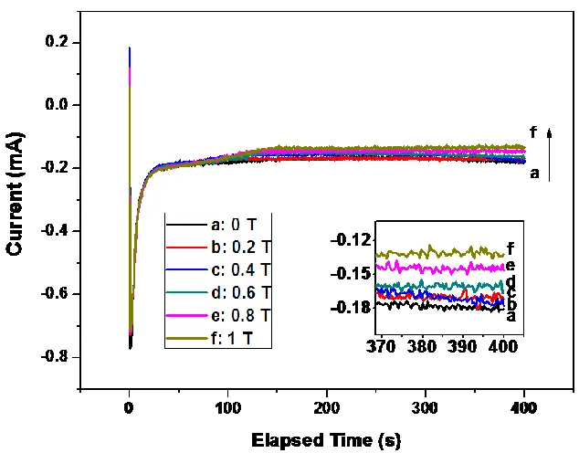
Electrochemical transient curves were used to study electrochemistry process of cobalt films prepared with various magnetic intensities. Effect of magnetic intensities on electrochemical transient curves applied with -1.2 VSCE is shown in Fig.3.
[image:4.596.141.458.458.706.2]
Regarding to Fig.3, with the increase of magnetic intensities, the steady state currents decrease gradually. When the magnetic intensity increased from 0 to 1 T, the steady state current declined from 0.18 to 0.12 mA. It is evident that higher magnetic intensity induces to obtaining smaller steady state currents at the same potentials. Georgescu and Daub[18] studied the magnetic effects on CoNiP films electrodeposition which was significant for our work. This is owing to the effects of magnetic driving forces. This force will be oriented in the direction of the concentration gradient. According to the conclusion above, cobalt deposition is based on diffusion controlling. A gradient in the concentration of paramagnetic cobalt ions leads to a gradient in the magnetic susceptibility which would induce to a magnetic driving force. This magnetic driving force would push the cobalt ions away from cathode to hinder cobalt deposition and decrease steady state current.
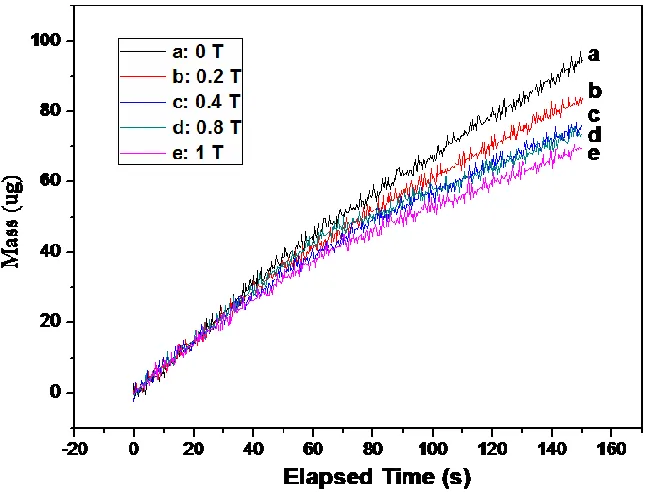
In order to verify the point that parallel magnetic field did hinder the cobalt deposition process, Quartzmicrobalance was used to monitor the mass changing during magnetic deposition process.
Figure 4. Mass changing of transient curves at -1.2 VSCE with different magnetic intensities ranged from 0-1 T in 0.01 M CoCl2 and 0.1 M NaCl solution
[image:5.596.139.463.304.550.2]
Table 1. Effects of magnetic intensities on driving force and deposition mass at -1.2 VSCE
Magnetic Intensity (T) Magnetic driving force (N/m3) Deposition Mass (μg)
0 0 95.6
0.2 55.8 82.5
0.4 223.2 76.7
0.8 893.4 74.1
1 1396 69.3
3.3 Electrochemical impedance of cobalt magnetic electrodeposition
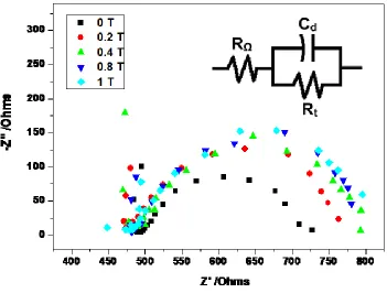
Electrochemical impedance method was studied in the paper to investigate the effects of magnetic intensity on mass transfer process in Fig.5.
Figure 5. Electrochemical impedance of cobalt magnetic plating process
[image:6.596.124.475.312.578.2]
intensity which could hinder the transfer rate of cobalt ions resulting in the increase of transfer resistance.
3.4 Surface Morphology of cobalt magnetic electrodeposition
Effects of magnetic field on morphology of cobalt films are shown in Fig.6.
Figure 6. AFM images of magnetic electrodepostion cobalt films
Fig.6 demonstrates AFM images of cobalt films deposited with different magnetic intensities. It is conspicuous that dissimilar AFM images could be detected under different magnetic intensities. Cobalt films are covered with typical nodular structures without magnetic field. However, with the increase of magnetic intensity, cobalt grains tend to grow perpendicularly to the substrate. Hill-like structures start to appear when 0.4 T magnetic field is applied.
[image:7.596.129.460.185.454.2]
4. CONCLUSION
Magnetic fields parallel to electric fields were introduced during the cobalt electrodeposition process to study the effects on electrochemistry mechanism, surface morphology and deposition mass of cobalt films. When the magnetic filed is parallel to the electric field, magnetic driving forces is dominant. During the plating process, concentration of cobalt near cathode is lower than other places in the solution. A gradient in the concentration of paramagnetic cobalt ions leads to a gradient in the magnetic susceptibility which would induce to a magnetic driving force in magnetic field. The magnetic driving force is proportional to concentration gradient and magnetic intensity which would hinder cobalt deposition process. The value of magnetic driving force increased from 55.8 to 1396 N/m3 when the magnetic field was ranged from 0.2 to 1 T. Regarding to the analysis of quartzmicrobalance, deposition mass of cobalt decreased from 95.6 to 69.3 μg with the increase of magnetic intensity. Moreover, higher magnetic intensity intends to decline steady state current during cobalt plating process. Without magnetic field, cobalt films possess typical spherical nodular structures. Grains of films tend to grow perpendicularly to the substrate with the increase of magnetic intensity. Hill-like structures started to appear with the magnetic increased to 1 T.
ACKNOWLEDGEMENT
This research was supported by the National Natural Science Foundation (No. 51471156 & 51401198), International Science and Technology cooperation Program of China (No.2011DFA52400) and China Postdoctoral Science Foundation (No.2014M560475).
Reference
1. Y.J. Kim, W.H. Park, S.H. Kong and K.H. Kim, Surf. Coat. Technol, 169 (2003) 532 2. Y. Ren, Q.F. Liu, S.L. Li, J.B. Wang and X.H. Han, J. Magn. Magn. Mater, 321 (2009) 226 3. F.H. Su, C.S. Liu and P. Huang, Appl.Surf.Sci, 258 (2012) 6550
4. N. Tsyntsaru, H. Cesiulis, A. Budreika and J.P. Celis, Surf.Coat.Technol, 206 (2012) 4262 5. C. C. Chen, R. Sakurai and M. Hashimoto, Thin Solid Films, 459 (2004) 200
6. A. Ispas, H. Matsushima, W. Plieth and A. Bund, J. Electrochim.Acta, 52 (2007) 2785 7. T. Z. Fahidy, J. Electrochem, 42 (2006) 506
8. M. Uhlemann, A. Krause and A. Gebert, J. Electroanal. Chem, 577 (2005) 19 9. M. Ebadi, W.J. Basirum and Y. Alias, Mater. Charact, 66 (2012) 46
10. Y.D. Yu, H.F. Guo and G.Y. Wei, Mater. Res. Innovations, 16(2012) 179
11. Y.D. Yu, Y. Cao, M.G. Li and H. Dettinger, Mater. Res. Innovations, 18(2014) 314 12. Y.D. Yu, Z.L. Song and G.Y. Wei, Surf. Eng, 30 (2014) 83
13. G. Sauerbrey, Z. Phys, 155 (1959) 206
14. Z.H.I. Sun, M. Guo and J. Vleugels, Curr. Opin. Solid State Mater. Sci, 16 (2012) 254 15. V. Ganesh, D. Vijayaraghavan and V. Lakshminarayanan, Appl. Surf. Sci, 240 (2005) 286 16. C. Su, M. An and P. Yang, Appl. Surf. Sci, 256 (2010) 4888
17. C.O. Reilly, G. Hinds and J.M.D. Coey, J. Electrochem. Soc, 148 (2001) C674 18. V. Georgescu and M. Daub, Surf. Sci. 600 (2006) 4195.
19. G. Hinds, J.M.D. Coey and M.E.G. Lyons, Electrochem. Commun, 3(2001) 215