THE DEVELOPMENT OF PORTABLE IN-SITU OPEN CIRCUIT
POTENTIAL TEST CELL
This report is submitted in accordance with requirement of the Universiti Teknikal Malaysia Melaka (UTeM) for Bachelor Degree of Manufacturing Engineering
(Engineering Materials) (Hons.)
by
MUHAMMAD FADZILAN BIN ABD LATIF B051410016
930217-07-5275
Disahkan oleh:
_____________________________ ______________________________ Alamat Tetap: Cop Rasmi:
_____________________________ _____________________________ _____________________________
Tarikh: _______________________ Tarikh: _______________________
*Jika Laporan PSM ini SULIT atau TERHAD, sila lampirkan surat daripada pihak berkuasa/organisasi berkenaan dengan menyatakan sekali sebab dan tempoh laporan PSM ini perlu dikelaskan sebagai SULIT atau TERHAD.
UNIVERSITI TEKNIKAL MALAYSIA MELAKA
BORANG PENGESAHAN STATUS LAPORAN PROJEK SARJANA MUDA
Tajuk: THE DEVELOPMENT OF PORTABLE IN-SITU OPEN CIRCUIT POTENTIAL TEST CELL
Sesi Pengajian: 2016/2017 Semester 2
Saya MUHAMMAD FADZILAN BINABD LATIF (930217-07-5275) mengaku membenarkan Laporan Projek Sarjana Muda (PSM) ini disimpan di Perpustakaan Universiti Teknikal Malaysia Melaka (UTeM) dengan syarat-syarat kegunaan seperti berikut:
1. Laporan PSM adalah hak milik Universiti Teknikal Malaysia Melaka dan penulis. 2. Perpustakaan Universiti Teknikal Malaysia Melaka dibenarkan membuat salinan
untuk tujuan pengajian sahaja dengan izin penulis.
3. Perpustakaan dibenarkan membuat salinan laporan PSM ini sebagai bahan pertukaran antara institusi pengajian tinggi.
4. *Sila tandakan (√)
(Mengandungi maklumat yang berdarjah keselamatan atau kepentingan Malaysiasebagaimana yang termaktub dalam AKTA RAHSIA RASMI 1972)
(Mengandungi maklumat TERHAD yang telah ditentukan oleh organisasi/ badan di mana penyelidikan dijalankan)
SULIT
TERHAD
DECLARATION
I hereby, declared this report entitled “The development of portable in-situ open circuit potential test cell” is the result of my own research except as cited in references.
Signature : ………
Author’s Name : MUHAMMAD FADZILAN BIN ABD LATIF
APPROVAL
This report is submitted to the Faculty of Manufacturing Engineering of Universiti Teknikal Malaysia Melaka as a partial fulfilment of the requirement for Degree of Manufacturing Engineering (Engineering Materials) (Hons). The member of the
supervisory committee are as follow:
i
ABSTRAK
ii
ABSTRACT
Coating testing is very crucial to determine coating defect and to prevent corrosion as well as degradation. There are many non-destructive methods to determine coating defects such as ultrasonic testing, magnetic testing and radiographic testing. Electrochemical measurement method is a powerful method that can detect coating resistances, pinholes and scratches. However, the electrochemical measurement method is usually used in the laboratory and requires the destruction of samples. Hence, the aim of this study is to design an electrochemical probe to measure surface potential of various coating defects. A sample of carbon steel ASTM A516 is coated with glass flake epoxy paint from Jotun until 1 mm thick. The coated carbon steel surface is made into square grid of 5 × 10 with area of 1 cm2 per square. Using prototype electrode made from pencil graphite and Cu/CuSO4 (saturated)
iii
DEDICATION
Only
my beloved father, Abd Latif bin Omar my beloved mother, Fatimah binti Hashim
my adored brother, Muhammad Dzul Farhan bin Abd Latif
iv
ACKNOWLEDGEMENT
In the name of ALLAH, the most gracious, the most merciful, with the highest praise to ALLAH than I manage to complete this final year project 1 successfully without difficulty.
My respected supervisor, Dr. Muhammad Zaimi Bin Zainal Abidin for the great monitoring that was given to me throughout the project. Besides that, I would like to express my gratitude for his kind supervision, advice and guidance as well exposing me with meaningful experiences throughout the study.
Last but not least, I would like to give a special thanks to my parents who always gave me much support in motivation and cooperation mentally in completing this report. I would like to thank to all my friends who help me by their supportive encouragement to complete this final year report.
v
TABLE OF CONTENT
Abstrak I
Abstract II
Dedication III
Acknowledgement IV
Table of Content V
List of Tables VIII
List of Figures IX
List of Abbreviations XI
CHAPTER 1: INTRODUCTION 1
1.1 Background of Study 1
1.2 Problem Statement 2
1.3 Objectives 3
1.4 Scope of study 3
CHAPTER 2: LITERATURE REVIEW 4
2.1 Corrosion 4
2.1.1 Corrosion Factors 5
2.1.1.1 Environment Factor 5
2.1.1.2 Temperature Factor 6
2.1.1.3 Stress Factor 6
2.1.1.4 Material Factor 7
2.1.2 Corrosion mechanism 7
2.1.3 Corrosion Protection 8
2.1.3.1 Coating 9
2.1.3.2 Galvanic Couples 9
2.1.3.3 Inhibitor 10
vi
2.2 Corrosion and Defect Detection Method 11
2.2.1 Non Destructive Test Method 11
2.2.1.1 Ultrasonic Testing 11
2.2.1.2 Radiography Testing 12
2.2.1.3 Magnetic Testing 12
2.2.2 Surface Detection Method 13
2.2.2.1 Visual Inspection 13
2.2.2.2 Kelvin Probe 14
2.2.2.3 Atomic Force Kelvin Probe 15
2.3 Electrode Potential Measurement 15
2.3.1 Reference Electrode 16
2.3.2 Counter Electrode 17
2.3.3 Working Electrode 17
2.4. Open Circuit Potential 18
2.4.1 Anodic Reactions 20
2.4.2 Cathodic Reactions 20
2.5 Portable In-Situ OCP Test Cell 22
2.6 Potentiodynamic Polarization Experiments 23
CHAPTER 3: METHODOLOGY 24
3.0 Introduction 24
3.1 Experimental Procedure 24
3.2 Design of the Probe 25
3.2.1 Pilot Test Prototype Design 26
3.2.1.1 Electrochemical Probe Pilot Test Prototype Parts 27
3.2.2 Probe Design by SolidWorks and 3D printing 28
3.3 Electrochemical Test 29
3.3.1 Reference Electrode 29
3.3.2 Counter electrode 30
3.3.3 Working Electrode 31
3.3.3.1 Test Sample 31
3.3.3.2 Surface Coating Defects Preparation 32
3.3.3.3 Test Solution, Electrolyte 32
vii
CHAPTER 4: RESULTS AND DISCUSSIONS 34
4.0 Introduction 34
4.1 Open Circuit Potential 34
4.2 Linear Polarization Curves 39
4.3 Open Circuit Potential with Tomography Image 40
4.4 Design of the electrochemical probe 42
4.5 Design of the electrochemical probe by using SolidWorks 2013 44
4.6 Actual Electrochemical Probe Prototype 47
CHAPTER 5: CONCLUSION AND RECOMMENDATION 49
5.1 Conclusion 49
5.2 Recommendation 50
5.3 Sustainable Design and Development 51
5.4 Complexity of the Project 51
5.5 Long Life Learning and Basic Entrepreneurship 51
REFERENCES 53
Appendix 1: PSM 1 Gantt Chart 56
viii
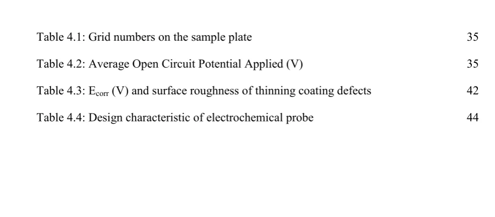
[image:12.595.49.540.155.371.2]LIST OF TABLES
Table 4.1: Grid numbers on the sample plate 35
Table 4.2: Average Open Circuit Potential Applied (V) 35
Table 4.3: Ecorr (V) and surface roughness of thinning coating defects 42
ix
LIST OF FIGURES
Figure 2. 1: The effect of different microbes and degradation mechanism 5 Figure 2. 2: Corrosion rate of metallic materials in HCl 6 Figure 2. 3: Methods, measurement and procedure of corrosion protection 9
Figure 2. 4: MFL pipe inspection 12
Figure 2. 5: Schematic diagram of the apparatus for measuring polarization curve 14
Figure 2. 6: Sample result of polarization curves 14
Figure 2. 7: The AFM tip of an SKPFM at different positions on a rough surface. 15
Figure 2. 8: Three electrode device. 16
Figure 2. 9: Example of CuSO4 Reference Electrode 17
Figure 2. 10: Open Circuit Potential Diagram 18
Figure 2. 11: The graph of OCP vs time 19
Figure 2. 12: Schematic of a charged interface and the locations of cations 21 Figure 2. 13: The separation of anodic and cathodic sites 22 Figure 2. 14: Bare Carbon steel after surface polished OCP 23 Figure 2. 15: Carbon steel linear polarization measurement in 3.5%wt of NaCl 23
Figure 3. 1: Experimental procedure 25
Figure 3. 2: Schematic diagram of design of Portable In-situ OCP Test Cell prototype 26
Figure 3. 3: Pilot test electrochemical probe 27
Figure 3. 4: Jelly (agar) 27
Figure 3. 5: Pen Tube 28
Figure 3. 6: Copper wire for reference electrode 29
Figure 3. 7: Saturated copper sulphate solution 30
Figure 3. 8: Graphite rod for Counter electrode 30
Figure 3. 9: Schematic diagram of the sample plate with marked gridlines 31
x
Figure 4. 3: Profiling measurement of surface coating defect scratch grid 4 38 Figure 4. 4: Profiling measurement of surface coating defect pinholes grid 27 38 Figure 4. 5: Profiling measurement of surface coating defect scratch grid 22 38
Figure 4. 6: Linear polarization measurement results 39
Figure 4. 7: Tomography image of average open circuit potential 40
Figure 4. 8: Test sample plate with various defects 40
Figure 4. 9: Different pinhole OCP on grid 5 and 15 41
Figure 4. 10: Different Scratch OCP on grid 10 and 20 41
Figure 4. 11: Different thinning coating OCP 42
Figure 4. 12: Pilot test prototype design 43
Figure 4. 13: Design 1 45
Figure 4. 14: Design 2 46
Figure 4. 15: Design 1 3D printed prototype 47
xi
LIST OF ABBREVIATIONS
AFM - Atomic Force Microscopy
ASTM - American Society for Testing and Materials ISO - International Standards Organization
NACE - National Association Corrosion Engineering
OCP - Open Circuit Potential
SKP - Scanning Kelvin Probe
1
CHAPTER 1
INTRODUCTION
1.1 Background of Study
2
Hence, it is possible to determine the surface of structure’s corrosion behaviour by observing the OCP changes versus time. Nevertheless, the OCP measurement is usually done in a laboratory, thus, it cannot be used for in-situ measurement in a chemical plant for example.
In this study, the surface OCP was measured using a portable electrochemical electrode cell designed for in-situ measurement. The portable electrochemical probe prototype was made for electrochemical testing and the OCP measurement is done on a surface of coated carbon steel with surface coating defects in grids to determine its feasibility. The probe composed of Cu/CuSO4 (saturated) and graphite as reference and
counter electrode respectively. The coated metal surface was used as working electrode with several defects in the grids. The electrolyte for the testing is 3.5wt% NaCl aqueous solution. Each square of the grid was measured and made into tomographic diagram. The actual design of the probe was designed using Solidworks software. The final design will be formed using 3D printer.
1.2 Problem Statement
3 1.3 Objectives
The objectives of this study are:
1. To design the electrochemical probe using SolidWorks software
2. To verify the surface potential measurement theory on various coating defect using electrochemical probe
1.4 Scope of study
A prototype electrochemical probe is made using recycled materials with Cu/CuSO4
4
CHAPTER 2
LITERATURE REVIEW
2.1 Corrosion
5
2.1.1 Corrosion Factors
According to Corrosion Inspection and Monitoring, 2006 there are four factors which could influence the corrosion. There are environment, temperature, stress and material factor (Roberge, 2006).
2.1.1.1 Environment Factor
[image:20.595.175.421.451.622.2]The environment that concern to the corrosion is the area which contact with the metal surface. Local cells are a driving force that can cause corrosion problem as these local cells cause differences nearby on metal surface area. Then, the corrosion behavior cause by the presence of microbes as one of the environment factors as it influence the degradation of the materials. Figure 2.1 shows the effect of different microbes degradation mechanism on materials (Roberge, 2006).
Figure 2. 1: The effect of different microbes and degradation mechanism (Roberge, 2006)
6
2.1.1.2 Temperature Factor
[image:21.595.207.401.237.530.2]The tendency of corrosion is influenced by the temperature changing of the solution and the temperature is increases results the chemical reaction rate to be increases. The figure 2.2 below shows the effect of temperature and composition towards corrosion action of material that reveal to hydrochloric acid solutions.
Figure 2. 2: Corrosion rate of metallic materials in HCl (Roberge, 2006)
2.1.1.3 Stress Factor
7
2.1.1.4 Material Factor
Unpredicted corrosion cause from the lack of material denotation. The composition of material grain boundaries is the material factor of corrosion. Most of the degradation reactions are through grain boundaries or started at grain boundaries. The presence and distribution of second phase result to the degradation reactions at grain boundaries or spread through the grains. Corrosion forms from the degree of the grain path. However, the grain structure is the factor that let the corrosion occur along grain boundaries. Long, wide, and very thin pancake-shaped grains are virtually essential for a high influence of the tendency to exfoliate (Roberge, 2006).
2.1.2 Corrosion mechanism
According to Fundamental of Corrosion, corrosion in aqueous solutions is common corrosion processes. Water, seawater, various process streams in industry provide in solution medium, moistures in the atmosphere and water in the soil effect to aqueous corrosion. So, water is rare in pure form while various salts and gases remain dissolved in it, and their separation makes the water as a conducting medium. This medium acts as an electrolyte and it comes in alkaline, acidic or neutral (Schweitzer, 2013).
Fe+2HCl→FeCl2 +H2 Equation 2.1
The chemical reaction above shows corrosion reaction involves the oxidation of pure metal when it exposed to acidic solution. This pure iron reacts with hydrochloric acid and result chemical reaction and the electrolyte begin to bubble rapidly. The reactions result to iron to be gradually disappears and the hydrogen bubbles moving upwards to the electrolyte surface and there are exchanges of electrons taking place while on this chemical reactions.
Fe(s) Fe2+ (aq) + 2 e- Equation 2.2
2H+ (aq) + 2 e- H
2 (g) Equation 2.3
8
The iron has been changed into the form of iron ion by release two electrons for oxidation reaction known as anodes while when the hydrogen ion was reduced by accepting the electrons, it known as cathodes and hydrogen gas is formed. The electrons transfer done on the metal surface. Anodes and cathodes with a complete electrical circuit will result a difference in electrical potential. The electrons flow in direction of from anode to cathode, as to complete the circuit the positively charged ions move toward the cathode. The current flow will be higher as the rate of corrosion is increases. Anodes and cathodes can be converted on the surface while the anodic areas moving uniformly over the metal’s surface. Anodic reaction is when the metal is oxidized to a higher valence state and result in the formation of metallic ions. Anodic reaction is where the dissolution of metal occurred then the release electrons consumed in the cathodic process.
2.1.3 Corrosion Protection
9
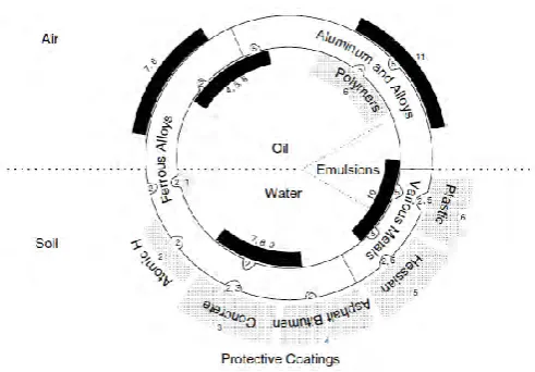
Figure 2. 3: Methods, measurement and procedure of corrosion protection (Maaß & Peißker, 2011)
2.1.3.1 Coating
ASM Metal Handbook Volume 13A: Methods of Corrosion Protection defines coating is the kind of surface protection between metal substrate and the environment from being oxidized. There are three type of coating which is organic, inorganic and metallic.
2.1.3.2 Galvanic Couples