UNIVERSITI TEKNIKAL MALAYSIA MELAKA
OPTIMIZATION OF INJECTOR GUN DESIGN USING DESIGN
FOR MANUFACTURING AND ASSEMBLY (DFMA) AT THE
CONCEPTUAL DESIGN STAGE
This report submitted in accordance with requirement of the Universiti Teknikal Malaysia Melaka (UTeM) for the Bachelor Degree of Manufacturing Engineering
(Manufacturing Design) (Hons.)
by
AZLINDA BINTI MOHAMAD B050910202
800130-01-5442
ABSTRAK
Setiap syarikat mahu menghasilkan produk yang berkos rendah, berkualiti tinggi dan dipasarkan dalam waktu yang singkat. Rekabentuk untuk Pembuatan dan Pemasangan merupakan satu konsep yang boleh aplikasikan untuk kebanyakan produk dalam industri pembuatan. Kajian ini menumpukan kepada kaedah Rekabentuk untuk Pembuatan dan Pemasangan Boothroyd-Dewhurst bagi menganalisa produk pistol suntikan (injector gun), yang memberi penekanan kepada pengurangan kos dan komponen. Tujuan kajian ini adalah untuk mengoptimumkan rekabentuk asal pistol suntikan pada peringkat rekabentuk konsep. Kajian ini mengaplikasikan perisian Rekabentuk untuk Pembuatan dan Pemasangan Boothroyd-Dewhurst sepenuhnya melalui dua jenis aplikasi iaitu perisian DFA untuk
ABSTRACT
Every company wants to produce low cost products, high quality and faster time to market. Design for Manufacturing and Assembly (DMFA) is a methodology that can be applied to many products in the manufacturing industry. This study focuses on Boothroyd-Dewhurst DFMA method to analyze the injector gun, which emphasis on cost reduction and parts count reduction. The purpose of this study is to optimize the current design of injector gun for oil palm tree fertilization application at the conceptual design stage. This study applies the DFMA Boothroyd-Dewhurst software by using two types of applications. The original design of the product was analyzed using DFA software applications to get the total assembly time, assembly
DEDICATION
To my beloved husband
Mohammad Aizrulshah bin Kamaruddin
my children
Muhammad Izzu Syahmi & Maryam Kayyisah
my mother Rufiah binti Jaafar
ACKNOWLEDGEMENT
First of all, I would like to thank my supervisor, Engr. Dr. Hambali Arep @ Ariff for his superior guidance and motivational advices. Without his constructive criticism, this project would not be successfully accomplished.
An utmost thanks to staffs at Faculty of Manufacturing Engineering, UTeM for their tolerance and cooperation. This project can be successfully carried out, thanks for their invaluable suggestion and cooperative efforts throughout the whole project.
TABLE OF CONTENTS
Abstrak i
Abstract ii
Dedication iii
Acknowledgement iv
Table of Contents v
List of Tables ix
List of Figures xi
List of Abbreviations, Symbols and Nomenclatures xiii
CHAPTER 1: INTRODUCTION 1
1.1 Background of Project 1
1.2 Problem Statement 2
1.3 Objectives 4
1.4 Scope of Project 4
CHAPTER 2: LITERATURE REVIEW 5
2.1 Product Design 5
2.2 Design Optimization 6
2.3 Conceptual Design Stage 8
2.4 Design for Manufacturing and Assembly (DFMA) 11
2.4.1 DFMA History 12
2.4.2 The Use of DFMA in Product Development Process 13
2.4.3 Design for Assembly (DFA) 14
2.4.4 Boothroyd Dewhurst DFA Method 16
2.4.5 Important of DFA 16
2.4.6 DFA in Product Design 18
2.4.7 Design for Manufacturing (DFM) 19
2.4.8 Application of DFMA in Different Industries 21
2.4.8.2 Automotive Industries 21
2.4.8.3 White Goods Industry 21
2.5 DFMA Software 22
2.5.1 DFA Software 22
2.5.2 DFM Software 28
2.6 Summary 33
CHAPTER 3: METHODOLOGY 34
3.1 Project Planning 34
3.2 The Overall Structure of the Project Work 37
3.2.1 Planning Phase 38
3.2.1.1 Define the Problem 38
3.2.1.2 Define the Problem Statement, Objective and Scope 38
3.2.1.3 Literature Review 39
3.2.1.4 Studying on Current Product 39
3.2.1.5 Methodology 39
3.2.2 Implementation of Analysis Phase 40
3.2.3 Redesign Phase 41
3.2.4 Discussion of the Report 41
CHAPTER 4: RESULTS AND DISCUSSION 42
4.1 Original Design 42
4.1.1 Assembly Tree of the Original Design 43 4.1.2 Bill of Material (BOM) of the Original Product 43 4.1.3 Parts Information about the Original Product 44
4.2 Analysis Results of the Original Design 44
4.2.1 DFA Result of the Original Design 47
4.2.2 DFM Result of the Original Design 50
4.2.3 DFMA Result of the Original Design 52
4.3 Suggestion for New Design 53
4.3.1 Combine Connected Item 54
4.3.2 Reduce the Number of Item 54
4.4 New Design 55
4.4.1 Assembly Tree of the New Design 56
4.4.2 Bill of Material (BOM) of the New Design 56 4.4.3 Parts Information about the New Design 57
4.5 Analysis Results of the New Design 59
4.5.1 DFA Result of the New Design 59
4.5.2 DFM Result of the New Design 61
4.5.3 DFMA Result of the New Design 62
4.6 Discussion 63
4.6.1 Modification of Original Design 63
4.6.2 Comparison between Original Design and New Design 68
4.7 Summary of Result and Discussion 70
CHAPTER 5: CONCLUSION AND FUTURE WORK 71
5.1 Conclusion 71
5.2 Future Work 72
REFERENCES 73
APPENDICES
A Boothroyd-Dewhurst Manual Handling Table B Boothroyd-Dewhurst Manual Insertion Table C1 Original Design Detail Drawing - Rod
C2 Original Design Detail Drawing–Yellow Plastic Washer C3 Original Design Detail Drawing–Butt Stock
C4 Original Design Detail Drawing–Catch Release Plate Spring
C5 Original Design Detail Drawing–Tin Hat Plunger C6 Original Design Detail Drawing–Trigger
C7 Original Design Detail Drawing–Pin
C8 Original Design Detail Drawing–Catch Plate
C9 Original Design Detail Drawing–Catch Plate Spring C10 Original Design Detail Drawing–handle
C11 Original Design Detail Drawing–Sleeve
C13 Original Design Detail Drawing–Steel Washer C14 Original Design Detail Drawing–Plastic Cap
C15 Original Design Detail Drawing–Barrel C16 Original Design Detail Drawing–Nozzle
C17 Original Design Detail Drawing–Nozzle Holder C18 Original Design Detail Drawing–O-Ring
D1 New Design Detail Drawing–Rod
D2 New Design Detail Drawing–Catch Release Plate
D3 New Design Detail Drawing–Catch Release Plate Spring D4 New Design Detail Drawing–Butt Stock
D5 New Design Detail Drawing–Catch Plate
D6 New Design Detail Drawing–Catch Plate Spring D7 New Design Detail Drawing–Plunger
LIST OF TABLES
2.1 Products design and time to market or incubation period 6
3.1 Gantt chart FYP 1 and FYP 2 35
4.1 BOM of the Original Design Injector Gun 44 4.2 Parts Information of the Original Design Injector Gun 45 4.3 DFA analysis result of the Original Design 49 4.4 Material and Manufacturing Process for Each Part of Original
Design
50
4.5 DFMA Analysis for Original Design Injector Gun 53 4.6 Suggested Part for Combine Connected Item 54
4.7 Suggested Parts for Reduce the Number of Item 54 4.8 Suggested Parts for Reduce Separate Operation Times 55
4.9 BOM of the New Design Injector Gun 57
4.10 Parts Information of the New Design Injector Gun 57
4.11 DFA analysis result for the New Design 60
4.12 Material and Manufacturing Process for Each Part of New Design 61 4.13 DFMA Analysis for New Design Injector Gun 63 4.14 Combining Rod and Handle Parts to Reduce the number of Items 64 4.15 Comparison Between Original Design and New Design in terms of
time and cost, after Combining the Rod and Handle
65
4.16 Combining Nozzle and Plastic Cap Parts to Reduce the number of Items
65
4.17 Comparison Between Original Design And New Design In Terms Of Time And Cost, After Combining The Nozzle And Plastic Cap
66
4.18 Combining the Lock nut, Split Sachet Plunger and Tin Hat Plunger Reduce the number of Items
66
4.19 Comparison Between Original Design and New Design in terms of time and cost, after Combining the Nozzle and Plastic Cap
4.20 Combining the Butt Stock, Steel Washer, Yellow Plastic Washer, Hexagonal Zinc Barrel Screw and Plastic Cap Reduce the number of Items
67
4.21 Comparison Between Original Design and New Design in terms of time and cost, after Combining : Combining the Butt Stock, Steel Washer, Yellow Plastic Washer, Hexagonal Zinc Barrel Screw and Plastic Cap
68
4.22 DFMA Results Comparisons Between Original and New Improved Design of Product
LIST OF FIGURES
1.1 Injector Gun Distributed by Cox North America 3
1.2 Syringe for Oil Palm Tree Fertilization 3
1.3 Exploded View of Injector Gun Product Modelling 3
2.1 Iterative model of the Engineering Design Process 9
2.2 Key Components of DFMA Process 12
2.3 Design Improvements of Automotive Panels by the DFA Process
15
2.4 Procedures for Processing Selection 20
2.5 DFA main window 23
2.6 Inserting Part to DFA Window 23
2.7 Example DFA Window for a Piston 24
2.8 Evaluation Criteria in DFA window 25
2.9 Example of Suggestion for Redesign of the Parts 26
2.10 Example of DFA for Redesign Piston 27
2.11 Main Analysis Window 29
2.12 Process and Material Selection Window 30
2.13 Main Analysis Window of a Valve 31
2.14 Examples of Parameters for the Semi-Automatic Sand Casting Process
31
2.15 Mold Core 1 Process Parameters 32
2.16 Graph of Cost Comparison between Two Processes 32
3.1 Flow Chart of FYP 37
4.5 The DFA Question for Barrel Part 48 4.6 The Breakdown of Assembly Time Per Product for the Original
Design
50
4.7 Total Manufacturing Cost per Part for Original Design 51 4.8 Manufacturing Cost Breakdown Chart Of Trigger Part 52 4.9 Chart of Cost Breakdown per Product for Original Design 53
4.10 Assembly Drawing of the New Design 55
4.11 Assembly Tree of the New Design 56
4.12 Exploded View of the New Design Injector Gun 57
4.13 Product Structure of the New Design 59
4.14 The Breakdown of Assembly Time Per Product for the Original Design
61
4.15 Total Manufacturing Cost per Part for New Design 62 4.16 Cost Breakdown per Product Chart for New Design DFMA
Analysis
63
4.17 Comparison between Original Design and New Design in Terms of Structural Complexity
64
4.18 Comparison between Original Design and New Design for an Injector Gun by Cost Breakdown Chart
LIST OF ABBREVIATIONS, SYMBOLS AND
NOMENCLATURE
ABS - Acrylonitrile Butadiene Styrene AHP - Analytical Hierarchy Process BOM - Bills of Material
CAD - Computer Aided Design CAE - Computer Aided Engineering CTQ - Critical to Quality
DFA - Design for Assembly DFM - Design for Manufacturing
DFMA - Design for Manufacturing and Assembly FYP - Final Year Project
HDPE - High Density Polyethylene PDP - Product Design Process PDS - Product Design Specification RM - Ringgit Malaysia
UTeM - Universiti Teknikal Malaysia Melaka
% - Percentage
Cm - Assembly Cost Ema - Design Efficiency
kg - Kilogram
Nmin - Theoretical Minimum Number Of Parts
s - Second
This chapter overall discusses about design optimization through implementing Design for Manufacturing and Assembly (DFMA) at the conceptual design stage. In this part, the briefing of the background, problem statement, objectives and scopes of the study are discussed.
1.1 Project Background
Nowadays, people are more demanding on something that simple and less costly in their daily requirement. In order to meet customer needs, more companies struggling with competitive markets to produce low cost products with high quality and faster to market. Many researchers and innovators have been carried out that focusing on increasing the efficiency and simplify the operation especially both assembly and manufacturing process and cost.
Improvement in many company’s operations is made by using a specific method.
Usually, in industry the improvement they made are based on cost reduction. The
reduction of cost could be made in the early stage of the design cycle. This means that cost estimation is an essential aspect in the design stage. Moreover, this is accepted that over 70% of final product costs is determined during the design stage (Boothroyd et al., 2002)
INTRODUCTION
2 Design for Manufacturing and Assembly (DFMA) is a method used by designers in a way to reduce part count, reduce assembly time or even during simplify the
sub-assemblies. It is a combination of Design for Manufacturing (DFM) and the Design for Assembly (DFA). DFM is a tool used to select the most cost effective material and process to be used in the production in the early stages of product design. DFA is a tool used to assist the product design teams to ensure the productions at a minimum cost, focusing on the number of parts, handling and ease of assembly.
Two different stages of DFMA implementation process are when existing design need improvement in order to achieve design optimization and in an early stage of the new design requirement is established. At the initial design stage, the designer develops a simple conceptual design by focusing on an assembly that requires a minimum of parts to perform and easy for installation. In the second stage the designer redesigns existing assemblies in order to optimize the design for ease manufacturing and installation (Herrera, 1997). Besides, in order to implement DFMA, the designer must have a good knowledge of the manufacturing process so that no additional unnecessary cost during the design development. Ease of manufacturing and assembly is important for cost, productivity and quality (Huang, 2001).
1.2 Problem Statement
Figure 1.1: Injector Gun (Cox North America, 2012)
Quantum Agro Solution is a supplier of special grade fertilizers for oil palm tree located in Petaling Jaya, Selangor. Currently, growers use only medical syringe for fertilizing as shown in Figure 1.2.
Figure 1.2: Syringe for oil palm tree fertilization
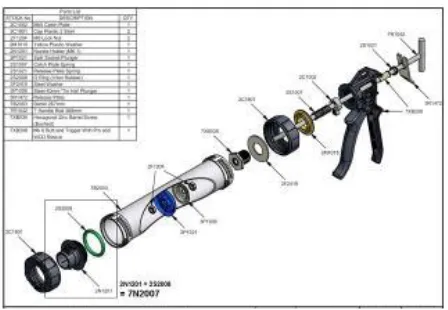
[image:20.595.229.409.384.511.2]4 Figure 1.3: Exploded View of Injector Gun Product Modelling (Cox North America, 2012)
1.3 Objectives
The main objective of this project is to design and develop a new conceptual design of injector gun. The specific objectives are as follows:
a) To analyze the current product of an injector gun using Boothroyd-Dewhurst DFMA software.
b) To design and analyze the improved injector gun using Boothroyd-Dewhurst DFMA software.
c) To evaluate the original design efficiency over new design efficiency.
1.4 Scopes of Project
The scopes of the project are as follows:
a) The use of injector gun as a case study product.
b) The use of Boothroyd-Dewhurst DFMA softwares for product evaluations. c) Product improvement for product structure simplification.
d) Comparison of product design efficiencies (DFA index).
This chapter covers the areas that need to be reviewed and understood before optimizing the product design by applying the DFMA concept. All information collected is derived from the findings of other peoples. In addition, it explains about DFMA software by Boothroyd-Dewhurst method and related matters in this study.
2.1 Product Design
Product design is generally conducted by a manufacturing enterprise whose primary purpose is to manufacture and sell products for a profit (Stoll, 1999). According to Chitale and Gupta (2007), product design deals with conversion of ideas into reality and fulfilling human needs. Product development and design are closely linked with industrial activity and production. When a new product is planned, the designer has to bear in mind the available resources of the plant and the possible impact of the firm having acquire, modify or substitute existing machines and equipment or buy various components from other suppliers. The important of product development and design for long-range planning by management is further emphasized by the amount
of time that elapses from the inception of the idea for the new design until production starts. Table 2.1 shows the period or time to market for several products.
LITERATURE REVIEW
6 Table 2.1: Products design and time to market or incubation period (Chitale & Gupta, 2007)
Product Time to Market
Automation bodies 2 years
Automobile engines 4-7 years
Radios and television sets 6-12 months Telecommunications equipment 4 years
Aircraft 10-15 years
Household equipment 2 years
Fashion Several weeks
In defense projects, where development and design take somewhat long time, because of the complexity of the problems involved, some design may become obsolete .
2.2 Design Optimization
According to Rao (1996), optimization is the act of obtaining the best result under given circumstance. Optimization can be defined as the process of finding the conditions that give the maximum or minimum value of the function. There is no single method available for solving all optimization problems efficiently and it can be applied to solve any engineering problem.
The goal of design optimization is to identify a design solution that satisfies all design requirements and is best in some sense. It can be based on cost, weight,
strength, capacity and so forth.in most design situations, the design team is constantly striving to optimize the design. Often, this is done on a subjective basis using engineering experience and general principles (Stoll, 1999).
optimization can be an excellent design improvement tool for performing parametric design (Stoll, 1999).
Chitale and Gupta (2007) identify four classifications of optimization in design approaches:
a) Optimization by Evolution
There is a close parallel between technological evolution and biological evolution. Most designs in the past have been optimized by an attempt to improve on an existing similar design. Survival of the resulting variations depends on the natural selection of user acceptance.
b) Optimization by Intuition
The art of engineering is the ability to make good decisions, without being able to provide a justification. Intuition is knowing what to do, without knowing why one
does it. The gift of intuition seems to be closely related to the unconscious mind.
c) Optimization by Trial-and-Error Modelling
This refers to the usual situation in modern engineering design, where it is recognized that the first feasible design is not always the best. Therefore, the design model is exercised for a few iterations, in the hope of finding an improved design.
d) Optimization by Numerical Algorithm
This is the area of current active development in which mathematically based strategies are used to search for an optimum. The computer is widely used for such an approach.