City, University of London Institutional Repository
Citation
:
Takeishi, K., Kawahara, G., Wakabayashi, H., Uhlmann, M. & Pinelli, A. (2015).
Localized turbulence structures in transitional rectangular-duct flow. Journal of Fluid
Mechanics, 782, pp. 368-379. doi: 10.1017/jfm.2015.546
This is the accepted version of the paper.
This version of the publication may differ from the final published
version.
Permanent repository link:
http://openaccess.city.ac.uk/14266/
Link to published version
:
http://dx.doi.org/10.1017/jfm.2015.546
Copyright and reuse:
City Research Online aims to make research
outputs of City, University of London available to a wider audience.
Copyright and Moral Rights remain with the author(s) and/or copyright
holders. URLs from City Research Online may be freely distributed and
linked to.
City Research Online:
http://openaccess.city.ac.uk/
[email protected]
Journal: Journal of Fluid Mechanics
Manuscript ID: Draft
mss type: Rapids
Date Submitted by the Author: n/a
Complete List of Authors: Takeishi, Keisuke; Osaka University, Department of Mechanical Science Kawahara, Genta; Osaka University, Department of Mechanical Science Uhlmann, Markus; Karlsruhe Institute of Technology, Institute for Hydromechanics
Pinelli, Alfredo; City University London, School of Mathematics, Computer Science and Engineering
Keyword: Transition to turbulence < Instability, Turbulent Flows
Under consideration for publication in J. Fluid Mech. 1
Localized turbulence structures in
transitional rectangular-duct flow
K E I S U K E
T A K E I S H I
1, G E N T A
K A W A H A R A
1,
†
H I R O K I
W A K A B A Y A S H I
1,
M A R K U S
U H L M A N N
2and
A L F R E D O
P I N E L L I
31Graduate School of Engineering Science, Osaka University, Toyonaka 560–8531, Japan 2Institute for Hydromechanics, Karlsruhe Institute of Technology, Karlsruhe 76131, Germany 3School of Mathematics, Computer Science and Engineering, City University London, London
EC1V 0HB, UK
(Received 12 October 2014)
Direct numerical simulations of transitional flow in a rectangular duct of cross-sectional aspect ratioA≡s/h= 1–9 (sand hbeing the duct half span and half height, respec-tively) have been performed in the Reynolds number rangeRe ≡ubh/ν = 650–1500 (ub andν being the bulk velocity and the kinematic viscosity, respectively) in order to inves-tigate the dependence on the aspect ratio of spatially localized turbulence structures. It was observed that the marginal Reynolds numberReT for sustaining turbulence mono-tonically decreases fromReT= 730 forA= 1 (square duct) with increasing aspect ratio and forA= 5 it nearly attains a minimal valueReT≈670 which is consistent with the onset Reynolds number of turbulence in a plane channel (A=∞). Marginally turbulent states consist of localized structures which undergo a fundamental change aroundA= 4. At marginal Reynolds numbers turbulence forA= 1–3 is streamwise-localized similar to turbulent puffs in pipe flow, while forA= 5–9 turbulence at marginal Reynolds numbers is also localized in the spanwise direction, similar to turbulent spots in plane channel flow. This structural change in marginal states is attributed to the exclusion of turbu-lence from the vicinity of the duct side-walls in the case of a wide duct withA4: here the wall shear rate on the side-walls is so low (and thus friction length is so long) that a self-sustaining minimal flow unit of streamwise vortices and streaks is larger than the duct height and, therefore, it cannot be accommodated.
Key words:Transition to turbulence, Turbulent flows
1. Introduction
Subcritical transition to turbulence can be triggered only by finite-amplitude perturba-tions. Since a fully nonlinear description is therefore indispensable for the transition, the elucidation of transition mechanisms and structures is much more challenging than in the case of supercritical transition. Subcritical turbulence transition in wall-bounded shear flows is known to be characterized in terms of the emergence of well-organized turbulence patches bounded by laminar regions. In circular pipe flow streamwise-localized turbulence has been observed by many investigators (see Mullin 2011). It is widely accepted that there are two kinds of localized turbulence structures, a puff and a slug (Wygnanski & Champagne 1973). Turbulent puffs appear at lower Reynolds number than slugs to
play a role in the early stage of transition. At low Reynolds numbers puffs can be in an equilibrium state where they have roughly 20 pipe diameter length (Mullin 2011) and propagate at a speed of approximately 0.9 times the bulk mean velocity (Nishiet al.2008; Wygnanski & Champagne 1973). The lowest value of the onset Reynolds number (based on the pipe diameter and the bulk mean velocity) of equilibrium puffs was estimated to be 1750 by Peixinho & Mullin (2006). In plane channel flow, on the other hand, two types of localized structures have been observed: one is a turbulent spot localized not only in the streamwise direction but also in the spanwise direction (Carlsonet al.1982), and the other is a turbulent stripe localized in the direction inclined from the streamwise direction in the spanwise direction (Hashimotoet al.2009). Turbulent spots first arise at lower Reynolds numbers, and as the Reynolds number increases they develop into stripes through their growth and subsequent break-up (Aidaet al.2010). Spots grow spatially in time, and their leading (or trailing) edge propagates at a speed of about 1.0–1.3 (or 0.5–0.8) bulk velocity (Carlson et al. 1982; Lemoult et al. 2013). An equilibrium state of spots like that of puffs has not been reported even at their onset, and equilibrium structures in a plane channel might be turbulent stripes rather than spots (Aidaet al.
2010). The onset Reynolds number (based on channel height and bulk velocity) of spots is around 1333 (Carlsonet al.1982; Hashimoto et al.2009).
The characteristics of subcritical transition to turbulence in rectangular-duct flow, including the shape of localized structures, should depend on cross-sectional aspect ratio
A of the duct, where A=s/h (1), s (h) andh being the duct half span and half height, respectively. In the case of a square duct (A = 1), on one hand, the transition characteristics are believed to be similar to those of pipe flow, and the appearance of streamwise-localized structures can be expected in a marginally turbulent state similar to turbulent puffs in a pipe. In the limit ofA→ ∞, on the other hand, the rectangular duct becomes equivalent to a plane channel such that the transition to turbulence will resemble that of plane channel flow, and marginal turbulence is represented by streamwise- and spanwise-localized structures, i.e. turbulent spots. Now the question arises: What is the structure of localized turbulence in transitional rectangular-duct flow for finite values of A larger than unity? In the present study, in order to reply to this question, direct numerical simulations of rectangular-duct flow were performed at transitional Reynolds numbers using a pseudospectral method (Pinelliet al.2010; Uhlmann et al.2007) in a long computational domain. It is shown how the marginal Reynolds number for sustained turbulence and the structure of marginally turbulent states depend on the geometrical aspect ratio of the duct. The dependence of marginal turbulence structures is interpreted in the light of scaling arguments with local wall units. Finally, the structural change of localized turbulence when increasing the Reynolds number is analyzed.
2. Flow configuration and numerical simulations
Localized turbulence in rectangular-duct flow 3
A ReT Reτ Δxuτ/ν max(Δyuτ/ν) max(Δzuτ/ν)
1 730 52.5 6.45 2.58 2.58
2 710 48.8 5.99 2.40 2.40
3 690 47.3 5.82 2.33 2.33
4 685 45.7 5.61 2.24 2.24
5 675 45.6 5.60 2.24 2.21
9 670 46.6 5.72 2.29 2.57
Table 1.Simulation parameters in typical runs
dimensionless control parameters are the Reynolds numberRe =ubh/ν and the aspect ratioA=s/h(1), whereν is the kinematic viscosity of the fluid.
We solve numerically the incompressible Navier–Stokes equations with a fractional-step method (see Pinelli et al. 2010, for the details of the numerical method and its validation). The time integration is based on the Crank–Nicolson scheme for the vis-cous terms and a three-step Runge–Kutta method for the nonlinear terms including the pressure term. The flow variables are expanded in terms of truncated Fourier series in thex-direction and Chebyshev polynomials in the (y, z)-directions. We use a collocated grid arrangement in physical space constructed from an equidistant spacing Δx in the
x-direction and the Chebyshev–Gauss–Lobatto points in the (y, z)-directions. The non-linear terms are evaluated in physical space whereas the explicit contribution of the non-linear terms is evaluated in spectral space. The fields are transformed back and forth by means of fast Fourier transform and fast cosine transform. De-aliasing according to the 2/3-rule is performed in thex-direction. In numerical simulations the aspect ratio is set atA= 1, 2, 3, 4, 5, 9 and the Reynolds number Re is changed in the range of 650Re 1500. In all the simulations the streamwise period is fixed atLx= 40πh.
3. Identifications of marginal turbulence
We first identify the marginal Reynolds numbers ReT which allow sustaining turbu-lence forA= 1–9. For each value ofAthe Reynolds number Re of the flow is gradually reduced by 5 units from Re = 1500 at which a fully developed turbulent state can be observed. After each reduction ofRe the computations are run until either the flow re-laminarizes or a minimum time 900u2τ/ν has elapsed, where uτ =τ/ρ is the friction velocity,τ andρbeing the averaged wall shear stress over the four walls and time, and the mass density of the fluid, respectively. The sustenance of turbulence is verified at every time step by monitoring the maximum value of the (positive) second invariantQ of the velocity gradient tensor (which represents vortex structures) over the whole flow field. If the maximum value ofQ(ν/u2τ)2 is greater than 2×10⁻³, then the turbulence is judged to survive at that time. For each value of the aspect ratio simulations are run with five distinct initial data among which the lowest value is identified as the marginal Reynolds number henceforth denoted asReT. It has been checked that changes in the threshold value forQ(ν/u2τ)2do not lead to significant difference inReT. The simulation parameters in the typical runs where the marginal Reynolds numbers have been identi-fied are shown in table 1. ThereinReτ =uτh/ν denotes the friction Reynolds number, and Δy and Δzare the grid intervals in they- andz-directions, respectively.
turbu-0 1 2 3 4 5 6 7 8 9 10 650
700 750 800
ReT
[image:6.595.102.401.100.286.2]A
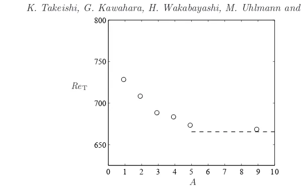
Figure 1.The marginal Reynolds numberReTas a function of the aspect ratioA. The dashed horizontal line denotes the value ofReT= 667.
lence is transient. If the duration time were longer, therefore, much higher values forReT
would be obtained. Near-wall turbulence is known to survive by the regeneration cycle consisting of streamwise vortices and streaks (Hamiltonet al. 1995), and the period of the cycle is about 282u2τ/νat the Reynolds numberRe= 1333 in the minimal flow unit (πh×2h×0.35πh) of plane channel turbulence (Jim´enez & Moin 1991). In this study, accordingly, the duration time has been set to be short in bulk time units but longer than the period of the near-wall regeneration cycle. A change of the duration time to 900u2τ/ν−400u2τ/ν (or +400u2τ/ν) was found to lead only to a slight variation of the marginal Reynolds number by−2.5 (or +10.8 ) on average.
Figure 1 shows the dependence of the marginal Reynolds numberReT on the aspect ratioA. The marginal Reynolds number for a square duct measures ReT = 730 which is lower than the recently reported critical Reynolds number, Re ≈ 1100, in a square duct with minimal streamwise extension (Uhlmannet al.2007). It is also lower than the onset Reynolds number (based on a pipe radius), Re = 875, of turbulent puffs in pipe flow (Peixinho & Mullin 2006). Let us define an equivalent radius of a square duct with half heighthin the sense of a consistent cross-sectional area asr= (2/√π)h; the marginal Reynolds number corresponding to pipe flow can then be expressed as (r/h)ReT= 824 which is much closer to the reported value 875. It can be seen from figure 1 that the marginal Reynolds number decreases monotonically with increasing A. When based on the maximum velocity of a laminar profile for a fixed bulk velocity the reduction of the marginal Reynolds number (not shown) is even more striking than that ofReT shown in figure 1. The monotonic decrease of ReT is thought intuitively to be a consequence of the weaker constraint which the side-walls in the wider duct impose on the flow. The stabilization of infinitesimal disturbances by the side-walls has also been found in laminar rectangular-duct flow (Tatsumi & Yoshimura 1990). For A= 5, however, the marginal Reynolds number nearly attains the minimal value of ReT ≈670 which is comparable to the onset Reynolds number for sustaining turbulent spots in a plane channel (Carlson
et al.1982; Hashimotoet al.2009).
4. Structures of marginal turbulence
We next discuss the turbulence structures at the marginal Reynolds numbersRe=ReT
visu-Localized turbulence in rectangular-duct flow 5
z/
h (a)
y/
h
x/h
z/
h (b)
y/
h
x/h
z/
h
(c)
y/
h
x/h
z/
h
(d)
y/
h
x/h
z/
h
(e)
y/
h
x/h
z/
h
(f)
y/
h
[image:7.595.147.432.106.656.2]x/h
2 4 6 8 10 0
0.2 0.4 0.6 0.8 1
ω2
xs
ω2
xl
[image:8.595.167.379.127.286.2]A
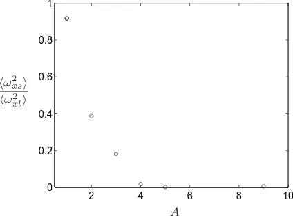
Figure 3.The relative turbulence intensityω2xs/ωxl2on the side-walls as a function ofA.
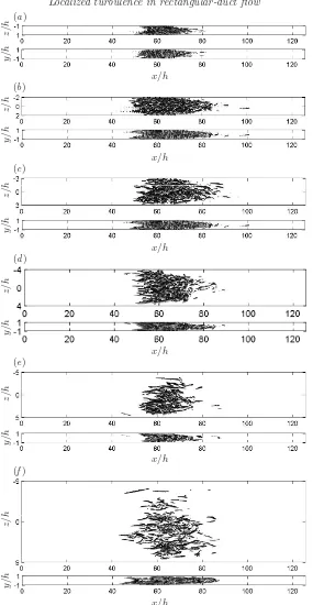
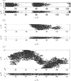
alized by positive isosurfaces of the second invariant of the velocity gradient tensor. It is observed that marginal turbulence structures exhibit spatial localization for all the values ofA. Localized turbulence can be seen to be composed of a large number of streamwise tubular vortices. For aspect ratios close to unity (A = 1–3) there appear streamwise-localized clusters of vortical structures which are strikingly similar to turbulent puffs in pipe flow (Wygnanski & Champagne 1973). Similar to equilibrium puffs in pipe flow the localized clusters forA= 1–3 do not extend or shrink in time, and their streamwise extent is about 30h–40hwhich is comparable with approximate 20 diameter length of the equilibrium puffs (Mullin 2011). For the larger aspect ratio (A= 4, 5, 9), on the other hand, the vortical structures are found to disappear from the vicinity of the side-walls (A= 4), and the vortical clusters are localized not only in the streamwise direction but also in the spanwise direction (A= 5, 9). The roundish clusters forA= 5,9 in figure 2 are reminiscent of turbulent spots in plane channel flow.
In the wider duct a spanwise localization of turbulence has been found in figure 2; however, this result might be subject to the choice of the threshold of isosurfaces. In order to supplement the demonstration of this crucial structural change withA, we shall compare turbulence intensity on the side-walls z/h =±A with that of the longer two walls y/h = ±1. As typical turbulence intensity on the walls, let us take the average,
ω2
xsor ω2xl, of the squared streamwise vorticity on the side-walls or the longer walls.
Here the average is performed over time and over the “vigorous streamwise extent”, the latter being defined as the streamwise interval in which ω2xyz 12maxωx2yz,
·yz denoting integration over the cross-plane. The turbulence intensity on the side-walls compared with that on the other side-walls,ωxs2 /ω2xl, is shown as a function ofAin figure 3. It can be seen that the relative turbulence intensity on the side-walls attenuates with increasing A. It is confirmed quantitatively that the turbulence on the side-walls significantly decays for A = 4,5,9. In the ducts of A = 5,9, for which turbulent spots have been observed, the turbulence on the side-walls has disappeared almost completely. The expulsion of turbulence from the vicinity of the side-walls should be a consequence of relaminarization of turbulent flow over the side-walls rather than the other two walls. In order to inspect this aspect we consider the behaviour of the main contributor to near-wall turbulence energy production,P =− uw∂u/∂z|y/h=0,over the side-wall
Localized turbulence in rectangular-duct flow 7
0 20 40 60 80 100
0 0.05 0.1 0.15 0.2 0.25 0.3
P ν/u3
τs
[image:9.595.154.382.101.268.2](z+s)uτs/ν
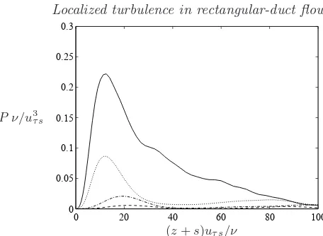
Figure 4.The turbulence productionP on the side-wall bisector y/h= 0 as a function of the distance from the side-wall. ,A= 2; ,A= 3; ,A= 4; ,A= 5.
and the vigorous streamwise extent, and the prime denotes a fluctuation around the average. As shown in figure 4, the turbulence production forA= 2 possesses a remarkable peak of about 0.22ν/u3τs around (z +s)uτs/ν = 12, which corresponds to that in a plane channel, where uτs is the friction velocity averaged on the side-wall over time and the vigorous streamwise extent. This outstanding production stems from buffer-layer streamwise vortices associated with streamwise streaks on the side-wall as in a plane channel. The turbulence production, however, decreases with increasingA, and for
A4 there is no longer any significant production.
In their numerical simulations of plane channel turbulence Jim´enez & Moin (1991) minimized the size of the periodic computational domain while sustaining turbulence activity, obtaining a minimal flow unit with a width of approximately 100 friction lengths, which accommodates a pair of counter-rotating staggered streamwise vortices and one low-velocity streak. If the width of the flow is less than this minimal value, turbulence dies out. Figure 5 shows the full width of the duct along the side-wall normalized with the friction length ν/uτs as a function ofA. It can be seen that the normalized width diminishes with increasingA, measuring approximately 100 forA= 2–3. This is a direct consequence of the lower wall shear rate (i.e. the increased friction length) on the side-walls of larger-aspect-ratio ducts for the fixed bulk velocity. For A4 the duct width 2h is smaller than 100 wall units, i.e. it cannot accommodate a minimal flow unit of near-wall turbulence. This is the reason why the flow in the vicinity of the side-walls relaminarizes, so that the spanwise-localized spots arise forA4.
5. Localized turbulence structures at higher Reynolds number
0 1 2 3 4 5 6 7 8 9 10 70
80 90 100 110 120 130
2h uτs/ν
[image:10.595.103.399.100.271.2]A
Figure 5.The full duct width 2halong the side-wall normalized with the friction length on the side-wall as a function ofA. The dashed horizontal line corresponds to the size 100ν/uτsof a minimal flow unit in plane channel flow.
z/
h
(a)
y/
h
x/h
z/
h
(b)
y/
h
x/h
z/
h
(c)
y/
h
x/h
[image:10.595.149.428.320.638.2]Localized turbulence in rectangular-duct flow 9
2 4 6 8 10
0 0.2 0.4 0.6 0.8 1
I
[image:11.595.172.379.125.283.2]A
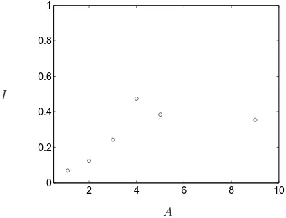
Figure 7.The skewness indicatorIof turbulence structures as a function ofAatRe= 800.
In order to examine quantitatively the dependence on the aspect ratio of the skew-ness of the localized turbulence at the higher Reynolds number, a skewskew-ness indicator is introduced as follows. At a given time t let us define f(x, z, t) = ωx2y/ωx2yxz as a two-dimensional ‘distribution function’ of a vortical cluster, where·xzdenotes the (x, z )-integration in the vigorous streamwise extent and ·y integrating over the y-direction. The relative coordinates (x, z) with respect to the centre of the vortical cluster are then defined asx =x−xfxz andz =z−zfxz. Now we compute the averaged modulus of the ‘cross correlation’ of (x, z) given by I ≡ xzfxz/x2fxzz2fxz which defines the skewness indicator I, where (·) represents an ensemble average over 25–70 realizations for each value ofA. In the computations the vigorous streamwise extent of a meandering cluster as in figure 6(c) is split into individual pieces with distinct skewness indicators. As shown in figure 7 the computed skewness of localized turbulence patches gradually increases with increasing A(except for a kink at A= 4 which is presumably due to a statistical error), attaining a plateau forA4.
6. Concluding remarks
Direct numerical simulations have been performed for transitional flow in rectangular ducts with various aspect ratiosA. The marginal Reynolds numberReTfor sustaining turbulence decreases monotonically from ReT = 730 for a square duct with increasing
A due to the weakening constraint by the side-walls in the wider duct, and for A = 5 it approaches the minimal valueReT ≈670 comparable to the onset Reynolds number of plane channel turbulence. Marginally turbulent states are characterized by spatially localized structures: there appear streamwise-localized turbulent puffs forA= 1–3, while streamwise- and spanwise-localized turbulent spots emerge forA= 5–9. Puff–spot tran-sition in localized marginal turbulence has been found forA≈4. The disappearance of turbulence from the vicinity of the side-walls is responsible for this critical change of the localized structures. In the wider duct flow withA4 the wall shear rate is so low (and thus the friction length is so long) on the side-walls that a self-sustaining minimal flow unit of streamwise vortices and low-velocity streaks is larger than the duct height and, therefore, it cannot be accommodated.
be followed by a theoretical demonstration. One candidate for a theoretical approach would be the characterization of localized structures in terms of invariant solutions to the Navier–Stokes equation (see Kawaharaet al.2012). Recently, a streamwise-localized relative periodic solution has been discovered in pipe flow (Avila et al. 2013) while a streamwise- and spanwise-localized relative periodic solution has been found in plane channel flow (Zammert & Eckhardt 2014). In rectangular-duct flow, to our knowledge, there are no reports of spatially localized invariant solutions; however, our own pre-liminary study suggests that a travelling-wave solution for A = 1 recently obtained by Uhlmannet al.(2010) would exhibit the spanwise localization when tracked toA >1. This latest finding might be a good starting point for a future theoretical demonstration of turbulence localization in transitional rectangular-duct flow.
This work was partially supported by a Grant-in-Aid for Scientific Research (Grant Numbers 25249014, 26630055) from the Japanese Society for the Promotion of Science.
R E F E R E N C E S
Aida, H., Tsukahara, T. & Kawaguchi, Y. 2010 DNS of turbulent spot developing into turbulent stripe in plane Poiseuille flow. In Proceedings of ASME 2010 3rd Joint
US-European Fluids Engineering Summer Meeting, pp. 2125–2130.
Avila, M., Mellbovsky, F., Roland, N. & Hof, B.2013 Streamwise-localized solutions at the onset of turbulence in pipe flow.Phys. Rev. Lett.110, 224502.
Carlson, D., Widnall, S. & Peeters, M. 1982 Flow-visualization study of transition in plane Poiseuille flow.J. Fluid Mech.121, 487–505.
Hamilton, J. M., Kim, J. & Waleffe, F.1995 Regeneration mechanisms of near-wall turbu-lence structures.J. Fluid Mech.287, 317–348.
Hashimoto, S., Hasobe, A., Tsukahara, T., Kawaguchi, Y. & Kawamura, H.2009 An experimental study on turbulent-stripe structure in transitional channel flow. InProceedings of the Sixth International Symposium on Turbulence, Heat and Mass Transfer, pp. 193–196. Hof, B., Westerweel, J., Schneider, T. M. & Eckhardt, B.2006 Finite lifetime of
tur-bulence in shear flows.Nature 443, 59–62.
Jim´enez, J. & Moin, P.1991 The minimal flow unit in near-wall turbulence.J. Fluid Mech.
225, 213–240.
Kawahara, G., Uhlmann, M. & van Veen, L. 2012 The significance of simple invariant solutions in turbulent flows.Ann. Rev. Fluid Mech.44, 203–225.
Lemoult, G., J.-L.Aider & Wesfreid, J. E.2013 Turbulent spots in a channel: large-scale flow and self-sustainability.J. Fluid Mech.731, R1.
Mullin, T.2011 Experimental studies of transition to turbulence in a pipe.Ann. Rev. Fluid
Mech.43, 1–24.
Nishi, M., ¨Unsal, B., Durst, F. & Biswas, G.2008 Laminar-to-turbulent transition of pipe flows through puffs and slugs.J. Fluid Mech.614, 425–446.
Peixinho, J. & Mullin, T.2006 Decay of turbulence in pipe flow.Phys. Rev. Lett.96, 094501. Pinelli, A., Uhlmann, M., Sekimoto, A. & Kawahara, G.2010 Reynolds number
depen-dence of mean flow structure in square duct turbulence.J. Fluid Mech.644, 107–122. Tatsumi, T. & Yoshimura, T. 1990 Stability of the laminar flow in a rectangular duct.J.
Fluid Mech.212, 437–449.
Uhlmann, M., Kawahara, G. & Pinelli, A.2010 Traveling-waves consistent with turbulence-driven secondary flow in a square duct.Phys. Fluids22, 084102.
Uhlmann, M., Pinelli, A., Kawahara, G. & Sekimoto, A.2007 Marginally turbulent flow in a square duct.J. Fluid Mech.588, 153–162.
Wygnanski, I. J. & Champagne, F. H.1973 On transition in a pipe. part 1. the origin of puffs and slugs and the flow in a turbulent slug.J. Fluid Mech.59, 281–335.