A Novel Protection Scheme for an LVDC
Distribution Network With Reduced Fault Levels
Dong Wang, Abdullah Emhemed, and Graeme Burt,
Dept. Electronic and Electrical EngineeringUniversity of Strathclyde, Glasgow, UK [email protected]
Abstract— Low Voltage Direct Current (LVDC) distribution is one of the new promising technologies that have the potential to accelerate the wider integration of distributed renewables. However, adding new power electronics to convert AC to DC will introduce new forms of faults with different characteristics. Converters with inherent fault current limiting and blocking capabilities will significantly limit the fault currents, resulting in significant impacts on the performance of existing LV overcurrent protection schemes. New protection methods based on the change in the DC voltages have been proposed recently by different researches. The issue with these methods is that the protection relays of the un-faulted feeders will also see the same change in the voltage for certain faults, leading to substandard selectivity and unnecessary tripping. This paper investigates these challenges, and presents a novel DC protection method which is based on the use of the combination of two components: the voltage change (dv/dt) and the change of current (di/dt). The new method is mainly developed to detect and locate DC faults with reduced fault current levels within DC distribution networks. The introduced protection concept is tested on an LVDC distribution network example using PSCAD/EMTDC simulation tool.
Keywords— DC protection, Modular Multilevel Converter, LVDC distribution networks.
I. INTRODUCTION
With the expanding demand of electronic loads and high penetration of renewables, an LVDC distribution network has become a competitive solution compared to the existing AC distribution networks. LVDC will eliminate AC-DC conversion losses and offer better controllability [1]. LVDC infrastructures have already been used for different niche applications such as data centres, traction systems and electric ships, but their use is relatively limited in the last mile utility applications [2][3]. Due to the lack of practical standards, DC fault protection and safety are considered as one of the remaining challenges that holds back the wide deployment of LVDC in the public distribution networks [3][4]. Previous research by the authors have concluded that LVDC distribution networks require high speed protection (<1ms) to avoid the damage to sensitive electronic loads which can be caused by DC fault currents [5]. Also, the use of existing traditional LVAC protection solutions will require longer time for detecting and clearing DC faults, resulting in the requirement for equipment with higher ratings [6]. This can be an issue when the LVDC network is interfaced to the AC grid using converters without fault management
techniques such as two and three level voltage source converters (VSCs).
As the power electronics technologies is advancing, modular multilevel converters (MMCs) (which has been widely proposed for HVDC applications) have the potential to be used for future LVDC distribution systems for better fault management and resilient operation[7][8]. However, their inherent fault current limiting and blocking capabilities will have a significant impact on inverse time graded DC overcurrent (O/C) protection schemes which are widely used in existing LV networks. The speed of such protection technique is directly influenced by the amount of the current contribution that can be supplied during the fault. Limiting the current during the fault to very low values for the converter internal protection may lead to protection failure for downstream faults. The research in[9] has proposed voltage-based protection called “Prony’s method” which uses the rate of change of the DC voltage to estimate the location of the fault. The challenge is that the DC voltage will collapse very rapidly across the LVDC network, and this will make even the protection relay of un-faulted feeders to react, leading to unnecessary trip for certain faults.
Therefore, this paper presents a novel and reliable protection scheme for protecting an LVDC distribution network with limited DC fault currents. The developed protection approach is based on the use of the combination of two important components: the rate of the voltage change (dv/dt) for the fault detection and the rate of the change of the current (di/dt) for the fault location. The multiplication of the dv/dt and di/dt is used for the protection coordination between different relays. The outline of this paper is as follows. Section II presents different DC fault characteristics of different converter topologies, and reviews a number of existing DC protection solutions that have been introduced by different researches. Section III describes the model of an LVDC distribution network interfaced by MMC. Section IV presents the developed DC protection scheme and the test simulation studies, and finally, the conclusion of the paper is given in section V.
II. DCFAULT CHARACTERISTICS OF DIFFERENT
CONVERTERS AND REVIEW OF EXISTING DCPROTECTION
SOLUTIONS
A. DC Fault Charcterisitcs of Different Converters
number of existing LVDC projects such as the Finnish LVDC distribution network research site presented in [10], Chinese-Danish DC microgrid cooperation project presented in [11], U.S.A hybrid microgrid test bed presented in [12], and the LVDC test lab in [13].The typical fault characteristics of two-level VSC and neutral point clamped converter have been previously analysed in details by the authors in [5]. Under faulted condition, these two converters will provide a significant transient and steady state fault currents as shown in Figure 1. This will require fast acting protection to reduce the impact of such high current.
[image:2.612.64.282.181.283.2]
Figure 1 DC fault responses of two-level VSC.
Comparatively, MMCs provides more powerful fault management capabilities, and this is driven by the converter types [7][14]. Figure 2 shows the fault characteristics of half bridge and full bridge MMCs. Compared to the fault current profile shown in Figure 1, the half-bridge MMC can only limit the fault current transient, and the full bridge MMC can block the DC fault current completely [15].
[image:2.612.65.282.395.498.2]
Figure 2 Fault current responses of full bridge and half bridge MMC.
Regarding to the DC/DC converters, the basic half-bridge DC/DC converters do not have the fault current management capabilities. Only the dual active bridge (DAB) DC/DC converter is capable of limiting the steady state fault current [16]. The typical fault current behaviour of the DAB DC/DC converter is shown in Figure 3.
Figure 3 Fault current of DAB DC/DC converter.
B. Review of Existing DC Protection Solutions
DC overcurrent (O/C) protection has been widely used in specific DC applications (e.g. solar photovoltaic systems, traction systems, and marine systems [3]). It has also been already used in the real LVDC research site given in [10]. The issue with using conventional overcurrent protection is the requirement for using overrated power electronics to withstand the significant fault current during faulted conditions. To address such challenges, a number of new protection approaches have been introduced by different researches. These include the rate of change of the current based protection [17], signal processing techniques (i.e. Fast Fourier transform and wavelet transform) based protection schemes [18][19], and converter coordinated protection scheme [20]. In addition, voltage resonance based protection has been proposed in [9] for protecting DC distribution network by extracting fault characteristics and estimating the distance of the fault and its locations.
Unit protection such as differential, directional protection and zonal protection using central processing unit have been also introduced for protecting LVDC systems [21][22][23]. Fast and selective protection can be achieved by such techniques only if high-speed communication links and solid state circuit breakers are used.
As for DC fault interruption devices, fuse and moulded-case circuit breaker (MCCB) have been used in solar photovoltaic [24], marine, and traction systems [25]. However, for achieving fast DC protection solutions, solid state circuit breakers (SSCBs) have been proposed for LVDC systems. SSCBs which use semiconductor devices such as GTO, IGCT, IGBT, and MOSFET can provide fast fault isolation (i.e. in the range of few ߤs [26]).
Compared to fully semiconductor based SSCB, hybrid SSCB is a more economical solution, which incorporates mechanical contactor and parallel connected semiconductor switches [27]. Generally speaking, SSCB devices for protecting LVDC systems are still not mature enough and have very limited applications.
[image:2.612.64.277.597.697.2]III. LVDCDISTRIBUTION NETWORK INTERFACED BY
MODULAR MULTILEVEL CONVERTER
[image:3.612.326.556.174.419.2]A simplified test network as shown in Figure 4 is modelled in PSCAD/EMTDC simulation tool and used for testing the developed protection scheme. The LVDC test network is connected to secondary substation of 11 /0.4 kV transformer by an MMC, which provides 750 V at the point of common coupling (PCC). Two main feeders (i.e. 0.75 km) are modelled with resistor (R=0.164 Ω/km) connected in series with an inductor (L=0.24 mH/km) [5], and supplying a number of DC loads.
Figure 4 LVDC distribution network.
[image:3.612.47.297.187.276.2]For the utilization of MMC in LVDC distribution networks, reference [29] has proposed using MOSFETs to replace the IGBTs of MMCs to achieve more efficient topologies for LVDC systems. In this section, the MMC is modelled as a full-bridge, and controlled by a vector and circulating current control with pulse width modulation and voltage balancing strategy following the instructions given in [30]. The full bridge modular multilevel converter provides active fault current limiting and blocking capabilities. The circuit schematic of the developed MMC model is shown in Figure 5, and the parameters are listed in Table I.
[image:3.612.44.298.405.620.2]Figure 5 Circuit schematic of MMC. Table 1 Parameters of MMC
Parameters Value
Output Voltage 750 V Arm Inductor 1 mH
Sub-module Capacitor 5000 uF Switching Frequency 1800 Hz
In normal operation, the vector control generates the AC voltage references which are required for the pulse width modulation to get the number of the submodules that can be inserted to the arm. Then, the selection of sub-modules is made by the voltage sorting algorithm. If the arm current flows in the charging direction, the sub-module with lower voltage will be chosen to insert to the arm first. When the arm current flows in
the discharging direction, the sub-module with the higher voltage will be chosen to insert to the arm first.
Under fault conditions, MMC can perform as a circuit breaker to block the fault current by switching off all the IGBTs or MOSFETs, and the current peak depends on the setting of the overcurrent trigger. In the developed MMC model, an active fault current controller as shown in Figure 6 used for limiting the output DC current of the MMC. With this method, the fault current can be limited to the expected level as shown in Figure 7, and the associated voltage performance is shown in Figure 8.
Figure 6 Control of MMC [31].
Figure 7 Current characteristics of MMC when fault current is limited.
Figure 8 Voltage Characteristics of MMC when fault current is limited.
The inherent fault current management capabilities of the MMC will enable the converter to be designed with lower ratings, however, it will influence the performances of traditional over-current protection. For example, the blocking of the main MMC for internal protection against downstream faults can introduce protection coordination issue between the converters and the network protection devices. The philosophy of the overcurrent protection for distribution networks is to clear and isolate the faults only from the faulted parts, and ensures non-faulted parts are not disconnected. This will require an effective coordination between the MMC internal protection and the downstream system protection.
[image:3.612.336.543.445.538.2]operate since the fault is reduced and the system can withstand the thermal impact for a longer time. However, if the control of converter is robust enough to limit the fault current to almost 1 p.u, overcurrent based protection will find it difficult to detect and locate the fault.
IV. AN ADVANCED PROTECTION SCHEME FOR DETECTING AND LOCATING DCFAULTS WITH LIMITED FAULT CURRENTS
A. Overview of the developed protection scheme
The developed protection approach incorporates active fault current limiting control of the MMC, protection relays based on electronic trip units, and mechanical breakers. The relay at each location of the main feeders measures the changes in the voltage and the currents and uses the multiplication of the (dv/dt)*(di/dt) as an indicator for the fault detection and location. The component dv/dt is used to detect the fault at different locations and the component di/dt is used to identify the fault directions which are used with the change in the voltage for locating the faults.
[image:4.612.341.540.372.437.2]The algorithm of the proposed protection scheme is shown in Figure 9 and explained as follows. Each protection unit are detecting di/dt, dv/dt, and (dv/dt)*(di/dt). When dv/dt is below the threshold, fault conditions are detected. Each protection unit has a threshold of (dv/dt)*(di/dt). The di/dt will be positive for the fault currents flowing downstream and negative for reverse fault currents. This will facilitate the location of the fault if it is within the protected zone. Based on the sign of the (dv/dt)*(di/dt), the DC faults will be located. In term of settings of the thresholds, for example, the threshold of the device ‘a’ (as shown in Figure 10) should be the value of the (dv/dt)*(di/dt) when the fault happens at bus 2. Also, with respect to the protection of MMC, the converter detects the (dv/dt), in order to coordinate with the nearest protection unit, MMCs can have up to 10 ms (arc extinction time for the DC circuit breaker [32]) time delay setting.
Figure 9 Flow chart of proposed protection scheme.
B. Simulation studies
In this section, the developed algorithm presented in Figure 9 is evaluated using two different LVDC examples (passive &
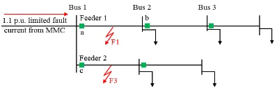
active LVDC with a local source). Five pole-to-pole faults (with 10 mΩ) are applied at f1 (at 125m from PCC of feeder1), f2 (at 375m from PCC of feeder 1), f3 (at 125m from PCC of feeder 2), f4 (at bus 1), and f5 (at the beginning of feeder 2). The MMC is set to limit the fault current to 1.1p.u.
(1) An LVDC distribution network with two passive feeders In this section, the performance of the protection scheme is tested on a passive LVDC distribution network as shown in Figure 10. The test starts with testing the suitability of using only the dv/dt as an indicator for the fault detection and location. For example, when f1 and f3 are applied, the dv/dt as seen by the relay “c” and relay “a” for both faults will be very similar as sown in Figure 11. This will make the two relays operate, and one of them will trip the un-faulted feeder. To address such problem, the introduced protection method in this paper proposes the use of the rate of the current change in addition to the voltage change to improve the protection selectivity.
[image:4.612.58.292.466.648.2]Figure 12 easily explains the change of the current in two different directions of the two fault (i.e. f1 and f3) with respect to the relay “c”. For the fault f1, the current seen by relay “c” will drop to zero and the di/dt will be negative (-) and vice versa for the fault f3. The dv/dt will be always negative for the both faults. This means that the dv/dv*di/dt of f1 for the relay c will be positive and the dv/dt*di/dt of f3 for the relay c will be negative as shown in Figure 13. Such differences can be effectively used to improve the selectivity and coordination between the relay “a” and “c” and the location of the fault.
[image:4.612.330.549.466.692.2]Figure 10 Simplified two passive feeders LVDC distribution network model.
Figure 11 dv/dt measured at relay “c” when f1 and f3 happens.
Figure 13 di/dt measured at relay “c” when f1 and f3 happens
(2) An LVDC distribution network with a local source
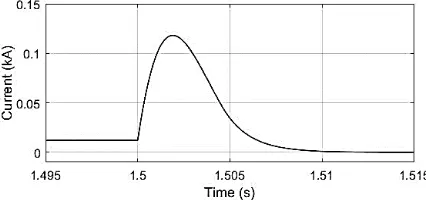
[image:5.612.67.273.56.163.2]In this section, a simplified active LVDC distribution network with a local source as shown in Figure 14 is used as a test model to assess the developed scheme against reverse fault currents. A distributed generator is added to the feeder 1 and modelled as a controlled current source to generate a limited fault current when the faults are applied at different locations.
Figure 14 Simplified two feeders active LVDC distribution network model with a distributed generator in feeder 1.
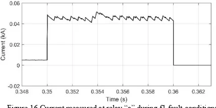
The (dv/dt)*(di/dt) threshold setting of the relay “a” is calculated to be -3.252E+14 (V/s)*(A/s). This is equivalent to a fault at bus 2 in respect to the relay “a” as shown in Figure 15. Based on this threshold value, the fault current can be interrupted by the relay “a” within 10 ms (see Figure 16).
Figure 15 (dv/dt)*(di/dt) measured at relay “a” during the f1 fault condition.
[image:5.612.338.544.117.217.2]Figure 16 Current measured at relay “a” during f1 fault conditions.
Figure 17 shows the (dv/dt)*(di/dt) of the relay “b” when the faults are applied at bus 1, at f1, at f2, and at bus 3 (see Figure 14). It can be seen that when the fault is applied on the feeder 1 between bus 1 and bus 2, (dv/dt)*(di/dt) of the relay “b” is bigger
than +1.84E+14 (V/s)*(A/s). Also, when the fault is located between bus 2 and bus 3, magnitude of (dv/dt)*(di/dt) of “b” is bigger than 3.992E+14 (V/s)*(A/s), but has a negative sign. With this threshold setting, the f1 fault can be cleared by device “b” within 10 ms as shown in Figure 18.
Figure 17 (dv/dt)*(di/dt) measured at b with different fault conditions.
[image:5.612.332.547.243.348.2]
Figure 18 Fault current measured at b during the f1 fault condition.
The above simulation results have demonstrated that the proposed protection method will provide an effective and reliable protection of the downstream feeders against different faults and at an early stage of the faults. But, for the fault at the PCC (i.e. fault f4 at bus1 in Figure 14) and fault f5, it will be challenging for the relay “c” and relay “a” to distinguish the fault f4 and f5. The (dv/dt)*(di/dt) measured by the relay “a” for the fault f4 and f5 will be very similar as shown in Figure 19. For the both faults, the (dv/dt)*(di/dt) will be positive and with similar magnitudes. To address this problem, an additional time delay are added to the relay “a” and “c” to improve the selectivity and the coordination between the two relays for faults at the PCC and at the beginning of the main feeders.
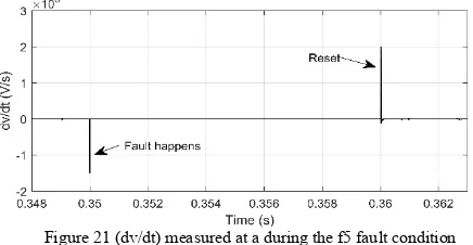
After the fault is cleared, the other relay will see a positive transient of dv/dt, and the relay will be reset as shown in the developed algorithm in Figure 9. The time delay is applied based on the condition of the (dv/dt)*(di/dt) as listed in Table 2 for the relay “a”. Figure 21 shows the results of the voltage measured by the relay “a” after the fault f5 is cleared. Figure 22 shows the relative dv/dt of the relay “a” for the same fault. After fault is cleared, the relay “a” will see a positive dv/dt that will reset the relay “a”. Therefore, with these additional settings, the relay “a” and relay “c” are capable of distinguishing the fault at the main bus and at the beginning of the feeders.
Table 2 Threshold setting of relay “a”
Sign of
[image:5.612.55.289.266.331.2] [image:5.612.72.282.428.529.2] [image:5.612.66.280.558.665.2]Figure 19 Current measured at c during the f5 fault condition
Figure 20 Voltage measured at a during the f5 fault condition
Figure 21 (dv/dt) measured at a during the f5 fault condition
The simulation results of this section has proven the resilience of the proposed protection method for protecting an LVDC with a reduced fault level using the (dv/dt)*(di/dt) as an indicator of the fault detection and location. The developed scheme relies on local measurement and no communication links are required for the protection coordination. Eliminating the need for communication and enabling the detection and interruption of reduced fault currents at early stage of the fault can potentially lead to reduced cost and avoid the use of ultra-fast fault breaking devices. The developed method is tested on a simplified LVDC, and it will be investigated further on more complicated networks and test lab facilities, and the results will be considered for future publications.
V. CONCLUSIONS
This paper has discussed the challenges in detecting and locating DC faults with reduced values caused by fault tolerant converters in LVDC last mile distribution network, and proposed a novel protection method to address these challenges. The new method is based on the use of (dv/dt)*(di/dt) to detect and locate different fault currents at different locations with reduced fault levels. The results have shown the credibility of this new method, and the benefits of the developed protection scheme will: allow the converters and cables of LVDC distribution networks to be designed with lower ratings, and
eliminate the need for communication links and ultra-fast solid state circuit breakers. In future LVDC distribution networks, fault current limiting technologies are likely to be widely utilised, and the proposed protection solution in this paper will be more promising compared to other existing current based and voltage based protection solutions.
REFERENCES
[1] A. Elsayed, A. Mohamed, and O. Mohammed, “DC microgrids and distribution systems: An overview,” Electric Power Systems Research, vol. 119. pp. 407–417, 2015.
[2] T. Dragičević, X. Lu, Q. Vasquez, and J. Guerrero, “DC Microgrids - Part II: A Review of Power Architectures, Applications, and Standardization Issues,” IEEE Trans. Power Electron., vol. 31, no. 5, pp. 3528–3549, 2016.
[3] K. Smith, D. Wang, A. Emhemed, S. Galloway, and G. Burt, “Overview paper on: low voltage direct current (LVDC) distribution system standards,” Int. J. Power Electron., 2017.
[4] M. Monadi, M. Zamani, J. Candela, A. Luna, and P. Rodriguez, “Protection of AC and DC distribution systems Embedding distributed energy resources: A comparative review and analysis,” Renew. Sustain. Energy Rev., vol. 51, pp. 1578–1593, 2015.
[5] D. Wang, A. Emhemed, G. Burt, and P. Norman, “Fault Characterisations of an Active LVDC Distribution Network for Utility Applications,” in
UPEC 2016, Sep 2016.
[6] A. Emhemed and G. Burt, “An advanced protection scheme for enabling an LVDC last mile distribution network,” IEEE Trans. Smart Grid, vol. 5, no. 5, pp. 2602–2609, 2014.
[7] V. Staudt et al., “Short-circuit protection in DC ship grids based on MMC with full-bridge modules,” in Electrical Systems for Aircraft, Railway and Ship Propulsion, ESARS, Mar 2015.
[8] Y. Zhong, N. M. Roscoe, D. Holliday, and S. J. Finney, “MOSFET Parallel-Connection of Low-Voltage MMC for LVDC Distribution Networks,” in IET Power Electronics, Machines and Drives, Apr 2016. [9] K. Jia, M. Li, T. Bi, and Q. Yang, “A voltage resonance-based
single-ended online fault location algorithm for DC distribution networks,” Sci. China Technol. Sci., vol. 59, no. 5, pp. 721–729, 2016.
[10] P. Nuutinen et al., “Research Site for Low-Voltage Direct Current Distribution in a Utility - Structure, Functions, and Operation,” IEEE Trans. Smart Grid, vol. 5, no. 5, pp. 2574–2582, 2014.
[11] E. Diaz, X. Su, M. Savaghebi, J. Vasquez, M. Han, and J. Guerrero, “Intelligent DC Microgrid living Laboratories - A Chinese-Danish cooperation project,” in 2015 IEEE 1st International Conference on Direct Current Microgrids, ICDCM 2015, Jun 2015.
[12] H. Mantooth, Y. Liu, C. Farnell, F. Zhang, Q. Li, and J. Di, “Securing DC and hybrid microgrids,” in 2015 IEEE 1st International Conference on Direct Current Microgrids, ICDCM 2015, Jun 2015.
[13] J. Cho, J. Kim, H. Lee, and J. Kim, “Design and construction of korean LVDC distribution system for supplying DC power to customer,” in
CIRED 2015, Jun 2015.
[14] T. Nakanishi, K. Orikawa, and J. Itoh, “Modular Multilevel Converter for Wind Power Generation System connected to Micro-grid,” in 3rd International Conference on Renewable Energy Research and Applications, Oct 2014.
[15] M. Winkelnkemper, L. Schwager, P. Blaszczyk, M. Steurer, and D. Soto, “Short circuit output protection of MMC in Voltage Source Control Mode,” in Energy Conversion Congress and Exposition, Sep 2016. [16] S. Acharya, K. Vechalapu, S. Bhattacharya, and N. Yousefpoor,
“Comparison of DC fault current limiting capability of various modular structured multilevel converters within a multi-terminal DC grid,” in
Energy Conversion Congress and Exposition, Sep 2015.
[17] A. Meghwani, S. Srivastava, and S. Chakrabarti, “A Non-Unit Protection Scheme for DC Microgrid Based on Local Measurements,” IEEE Trans. Power Deliv., vol. 32, no. 1, pp. 172–181, 2016.
[image:6.612.63.281.315.428.2][19] O. Nanayakkara, A. Rajapakse, and R. Wachal, “Traveling-wave-based line fault location in star-connected multiterminal HVDC systems,” IEEE Trans. Power Deliv., vol. 27, no. 4, pp. 2286–2294, 2012.
[20] P. Cairoli, I. Kondratiev, and R. Dougal, “Coordinated control of the bus tie switches and power supply converters for fault protection in DC microgrids,” IEEE Trans. Power Electron., vol. 28, no. 4, pp. 2037–2047, 2013.
[21] S. Fletcher, P. Norman, K. Fong, S. Galloway, and G. Burt, “High-speed differential protection for smart DC distribution systems,” IEEE Trans. Smart Grid, vol. 5, no. 5, pp. 2610–2617, 2014.
[22] A. A. S. Emhemed, K. Fong, S. Fletcher, and G. Burt, “Validation of Fast and Selective Protection Scheme for an LVDC Distribution Network,”
IEEE Trans. Power Deliv., vol. 32, no. 3, pp. 1–1, 2017.
[23] M. Monadi, C. Gavriluta, A. Luna, J. Candela, and P. Rodriguez, “Centralized Protection Strategy for Medium Voltage DC Microgrids,”
IEEE Trans. Power Deliv., vol. 32, no. 1, pp. 430–440, 2017.
[24] Eaton, “Complete and reliable solar circuit protection,” 2016, available at: http://www.eaton.com.
[25] ABB, “ABB circuit breakers for direct current applications,” 2010, available at: https://library.e.abb.com.
[26] Z. Shen, Z. Miao, and A. M. Roshandeh, “Solid state circuit breakers for DC micrgrids: Current status and future trends,” in 2015 IEEE First International Conference on DC Microgrids (ICDCM), Jun 2015. [27] W. Hauer and M. Bartonek, “A Novel Low Voltage Grid Protection
Component for Future Smart Grids,” in UPEC 2016, Sep 2016. [28] D. Wang, A. Emhemed, P. Norman, and G. Burt, “Evaluation of Existing
DC Protection Solutions on the Performance of an Active LVDC Distribution Network under Different Fault Conditions,” in CIRED 2017, Jun 2017.
[29] Y. Zhong, N. M. Roscoe, D. Holliday, and S. J. Finney, “MMC with Parallel-connected MOSFETs as an Alternative to Wide Bandgap Converters for LVDC Distribution Networks,” J. Eng., pp. 1–19, 2017. [30] Q. Tu, Z. Xu, and L. Xu, “Reduced Switching-frequency modulation and
circulating current suppression for modular multilevel converters,” IEEE Trans. Power Deliv., vol. 26, no. 3, pp. 2009–2017, 2011.
[31] J. Hu, R. Zeng, and Z. He, “DC fault ride-through of MMCs for HVDC systems: a review,” J. Eng., vol. 1, no. 1, pp. 1–11, 2016.
![Figure 6 Control of MMC [31].](https://thumb-us.123doks.com/thumbv2/123dok_us/1497501.102445/3.612.326.556.174.419/figure-control-of-mmc.webp)