City, University of London Institutional Repository
Citation
:
Marichal, N., Tomas-Rodriguez, M., Hernandez, A., Castillo, S. & Campoy, P. (2013). Vibration reduction for vision systems on board UAV using a neuro-fuzzy controller. Journal of Vibration and Control, 20(15), pp. 2243-2253. doi: 10.1177/1077546313479632This is the accepted version of the paper.
This version of the publication may differ from the final published
version.
Permanent repository link:
http://openaccess.city.ac.uk/12547/Link to published version
:
http://dx.doi.org/10.1177/1077546313479632Copyright and reuse:
City Research Online aims to make research
outputs of City, University of London available to a wider audience.
Copyright and Moral Rights remain with the author(s) and/or copyright
holders. URLs from City Research Online may be freely distributed and
linked to.
using a neuro-fuzzy controller
G. Nicolás Marichal 1, María Tomás-Rodríguez 2, Ángela Hernández 1, Salvador
Castillo-Rivera 2, P. Campoy 3
1 Departamento de Ingeniería de Sistemas y Automática,
Arquitectura y Tecnología de Computadoras, Universidad
de La Laguna, Spain
2 The Engineering and Mathematics Department. City
University, United Kingdom
3 Grupo de Visión por Computadoras. Universidad
Politécnica de Madrid, Spain
Corresponding autor:
Ángela Hernández López, Facultad de Física,
C/Astrofísico Francisco Sánchez s/n 38200, La Laguna,
España
EMail: [email protected];
Abstract:
In this paper, an intelligent control approach based on Neuro-Fuzzy systems
performance is presented with the objective of counteracting the vibrations that affect
A scaled dynamical model of a helicopter is used to simulate vibrations on its
fuselage. The impact of these vibrations on the low-cost vision system will be assessed
and an intelligent control approach will be derived in order to reduce its detrimental
influence.
Different trials that consider a Neuro-Fuzzy approach as a fundamental part of an
intelligent semi-active control strategy have been carried out. Satisfactory results have
been achieved compared to those obtained by means of vibration reduction passive
techniques.
Keywords
Vibration, control, neuro-fuzzy, model, intelligent.
Introduction
Rotary–wing unmanned aerial vehicle (UAV) systems are greatly affected by
vibrations frequently originated on its rotors. The characteristics (frequency and
amplitude) of these vibrations often lead towards detrimental performance of the
vehicle´s on-board systems.Vision systems onboard UAVs are subject to high dynamic
vibrations from several sources, such as the engine or the rotor blades. These
multi-modal spectrum vibrations cause a significant degradation in the quality of the captured
images, especially in small size aircrafts. In these cases, there is a need for reducing the
vibration influence over the captured images by designing and implementing an
Several studies have been developed in order to compare different techniques (Jansen et
al. 1999), (Miller et al. 1988). Passive vibration reduction devices are the most classical
methods, consisting of springs that support the load, and dampers that dissipate energy.
These systems require no external power or computer processes for operation. Once the
isolation mechanism is installed, its properties cannot be modified; therefore the major
disadvantage of passive vibration reduction systems is the lack of adaptability to
changes during flight operations. On the other hand, active control techniques have the
capability to adapt whilst changing flight conditions, overcoming in this way one of the
passive methods major drawbacks. Nevertheless, active control presents an important
limitation as it requires an external power source. Since the 70’s, the advantages of
using semi-active devices have been addressed in several studies (Karnopp et al. 1974),
(Rakheja et al. 1985, 1986). Years of studies have shown that these methods continue
improving since they have set better techniques (Alanoly et al. 1987), (Wu et al. 1997).
In fact, they do have low energy requirement which is a desirable characteristic in the
UAVs systems environment. Mainly, semi-active isolation systems consist of a variable
damping device such that the damping properties can be modified in real time in order
to provide significant vibration reduction in onboard vision systems. Therefore, this
adaptive damping methodology is especially useful for the cases where spectrum is of
In this article, an intelligence control strategy based on a semi-active approach is
presented in order to improve the performance of a low-cost vision system onboard a
UAV. In the following section, a description of the simulation model of the helicopter
prototype used for vibration generation is given. The next one explains the simulation
environment where the semi-active control strategy is applied on the vision system.
Next, it is focused on the description and application of an Adaptive Neuro-Fuzzy
Inference System as control approach. Finally, the results obtained are shown.
Furthermore conclusions and suggestions of further work are presented in the last
section.
Helicopter simulation model
Rotorcrafts are mechanically complex, with many bodies, several degrees of freedom
and general motions in three dimensions possible. Since the 60´s, the modeling of
helicopter dynamics has been technically challenging. In the late 80´s, improving
understanding and advances in computation allowed progress to accelerate. Nowadays,
studies in this area are extremely wide, as they entail amongst others, advanced methods
in computational fluid dynamics (CFD) and flexible multibody dynamics (Narramore,
1995). The majority of existing models in the literature tend to be relaxed in reflecting
the full set of dynamics involved in helicopter behavior. Several of the existing results
to date have been based on linearised models (Garrad et al. 1990), (Kienitz et al. 1990).
whilst in forward flight such dynamics turn out to be time-periodic (Bittanti et al. 1996),
(Johnson, 1980) with period equal to the rotor revolution period. On the other hand,
there exist some nonlinear descriptions of helicopter dynamics but only for reduced
order models (Kaloust, 1997) or without taking into consideration the interaction of the
main rotor with the fuselage (Verdult et al. 2004). The model here presented is a
realistic nonlinear model of the fundamental dynamics of an articulated rigid-bladed
rotorcraft. One of the advantages of this model is that it gives an accurate representation
of the complex system´s dynamics.
It consists of a 6 DOF (Degrees of freedom) fuselage plus an articulated main rotor
consisting of a set of four blades and a tail rotor with two blades. This model does take
into account highly coupled nonlinear dynamic terms and no approximations are taken,
in the same line as the analytical results published in (Decker et al. 1982), (Heffley et al.
1988), (Padfield, 1996) which constituted the starting point for a significant number of
helicopter flight simulations, in military and research fields.
A helicopter can be defined in a very general way as an aircraft that uses rotating
wings to provide lift, propulsion and control.
The fuselage is the rotorcraft’s main body section that holds crew and passengers or
cargo. Its degrees of freedom are the lateral and longitudinal translation in the horizontal
plane (X-Y axis), vertical translation (Z axis) and rotation about these same axes
corresponding to yaw, feather and roll.
The main rotor generates the thrust that supports the weight and controls the aircraft.
It transfers prevailingly aerodynamic forces and moments from the rotating blades to the
non-rotating frame (fuselage); a conventional rotor consists of two or more identical
equally spaced blades attached to a central hub. The blades are kept in uniform
rotational motion (rotational speed Ω) by a shaft torque from the engine. A common
design solution adopted in the development of the helicopter is to use hinges at the
blades roots that allow free motion of the blade normal to and in the plane of the disk.
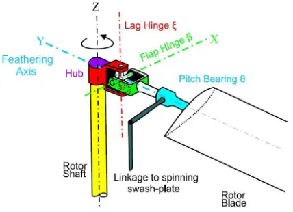
The rotor considered in this article is an articulated rotor; the blades are attached to the
[image:7.595.192.406.505.660.2]hub by flap β, lag ζ and, feather θ hinges, (see figure 2).
The most common of these hinges is the flapping hinge which allows the blade to
flap, this is, to rise and fall in similar manner to the beating of a bird’s wing. In some
cases, the flap hinge is substituted by a region of structural flexibility at the root of the
blade. The flapping hinge is usually at a short distance from the rotor center-line, termed
“offset flapping hinge”. Centrifugal stiffening due to rotor spin is vital to a blade’s
integrity in helicopter flight (http://avia.russian.ee). A spinning blade which also flaps,
experiences large Coriolis moments about the vertical, lag-hinge axes. The lag hinge
provides stress-relief at the blade root. This degree of freedom produces blade motion in
the disk plane. The lagging angle is considered to be positive when opposite the
direction of rotation of the rotor, as produced by the blade drag forces.
Blade feathering motions, θ (also known as angle of attack) need to be controlled to
regulate the aerodynamic lift developed and, in forward motion to allow the advancing
blade to have a lower angle of incidence than the retreating blade and to thereby balance
the lift across the craft´s rotor plane. Feathering the blades simultaneously is referred to
as collective feather control, whilst feathering them differentially is called cyclic feather
control. Blade feathering control is achieved through linkage of the blade to a
swash-plate, (see figure 2), the pilot having control of the height (collective) and angle (cyclic)
of the plate through a joy-stick.
The helicopter fuselage tends to rotate in the direction opposite to the rotor blades.
rotor. The tail rotor of the helicopter is mounted on the tail of a single-rotor helicopter,
perpendicular to the main rotor. It is used in order to counteract the torque and the yaw
motion that the main rotor disk naturally produces. Two anti-torque pedals allow the
pilot to compensate for torque variance by providing a means of changing pitch (angle
of attack) of the tail rotor blades. This provides heading and directional control in hover
and at low airspeeds.
In addition to counteracting torque, the tail rotor and its control linkage also allows
control of the helicopter heading during flight. Application of more control than is
necessary to counteract the torque will cause the nose of the helicopter to swing in the
direction of pedal movement. To maintain a constant heading at a hover or during
takeoff or approach, the pilot must use the antitorque pedals to apply just enough pitch
on the tail rotor to neutralize torque and hold a slip if necessary. Heading control in
forward trimmed flight is normally accomplished with cyclic control.
After introducing the main dynamical characteristics of a helicopter, the modeling
aspects will be addressed in the following subsections.
Dynamical modelling tool: VehicleSim
VehicleSim (http://www.carsim.com/) is one of a number of multibody modeling
systems currently in common use. The system has been used over a wide range of
mechanical dynamic problems, mainly in connection with vehicle dynamics (Sharp et
2007) and it has provided the basis for the commercial simulation codes TruckSim,
CarSim and BikeSim (http://www.carsim.com/). VehicleSim is a set of LISP macros
(Steele et al. 1984), enabling the description of mechanical multibody systems, with
possible addition of non-mechanical subsystems.
The output from VehicleSim takes one of several forms: (a) a Rich Text Format file
containing the symbolic equations of motion of the system described; (b) a ”C”
language simulation program with appropriate data files containing parameter values
and simulation run control parameters (or Simulink S-function); or (c) linear state-space
equations in a Matlab ”M-file” format that contains symbolic state-space A, B, C, D
matrices for linear analysis. Once the model has been built, it becomes independent of
VehicleSim and it can be executed at any time. VehicleSim commands are used to
describe the components of the helicopter multibody system in a parent-child
relationship according to their physical constraints and joints. The VehicleSim code is
then used to generate a C simulation program, capable of computing general motions
corresponding to specified initial conditions and external forcing inputs.
Simulations for vibrations generation
The complete dynamical helicopter model was implemented as described in section 2
(more details on modeling of this system can be found in (Tomás-Rodríguez et al. 2007)
and (Tomás-Rodríguez et al. 2008)). The model parameters are as follows: the main
rotor blade is lm= 4.91 m and the rotational speed of the rotor is Ωm=44.4 rad/s. The
main rotor blades moments of inertia on the X and Z axis are Ix=Iz=62.4 Kg·m2 and the
on the Y axis Iy=0.07488 Kg·m2, are the same for each blade. The fuselage mass is
mf=2200 kg. The height of the rotor disk above the fuselage is h= 1.48 m. The tail rotor
is composed of two blades each of mass mt=6.212 Kg. The length of each blade is
lt=0.982 m and the rotational speed of the tail rotor is Ωt=222 rad/s. The tail rotor
blades moments of inertia on the X and Z axis are Ix=Iz=12.48 Kg·m2 and on the Y axis
is Iy=0.015 Kg·m2, these are the same for each blade.
The fuselage is allowed 6 degrees of freedom, longitudinal, lateral and vertical along
the axes X, Y, Z respectively and the corresponding rotations about these same axes.
The acceleration of gravity is neglected for the purpose of these simulations as the
object of study is the dynamic behavior of the various subsystems of the helicopter and
the forces and accelerations that occur as a result of interactions and couplings between
them.
In order to study the characteristics of the vibrations occurring in the fuselage due to
the main rotor only, a simulation is carried out where the main rotor has an angular
velocity of Ωm=44.4 rad/s, and the tail rotor speed is fixed at Ωt=0 rad/s. As the main
objective at this stage is vibration generation, a mass imbalance is introduced
mb=15.53 kg, which will cause vibrations to appear and to be transmitted to the
fuselage.
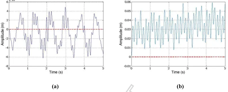
[image:12.595.99.495.204.364.2](a) (b)
Figure 3: (a) Vibrations appearing in Z-axis (blue solid line) when main rotor blade mass imbalance is
included in the simulation. (b) Vibrations appearing in Y-axis (blue solid line) when main rotor mass
imbalance is included in the simulation. The red dotted line on both cases represents the fuselage
steadiness when no mass imbalance is introduced.
In figure 3 the vibrations appearing on both Z and Y-axis are shown for a length of
time of T=5 seconds. The simulations were run for a period of 50 seconds and the
corresponding data were analyzed using a FFT (Fast Fourier Transform) algorithm. The
main frequency component of the spectrum of vibrations appearing in the Z-axis was of
f=50.58 rads/s, whilst the main frequency component of the vibrations appearing in the
Y-axis had a frequency of f=44.04 rads/s. These range of frequencies agree with those
predicted by the theory and will be used later on in this work in order to design the
At this point, the knowledge on the expected frequencies allows us to narrow our attention to this particular range and to perform a more exhaustive analysis over the problematic frequencies.
Experimental set-up
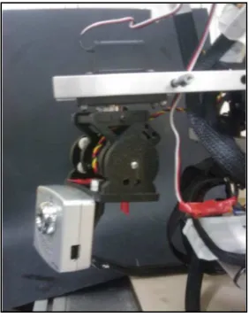
The vision system is one of the most susceptible elements to suffer from detrimental effects of the vibrations produced by the helicopter. To study the magnitude of this effect, a dynamic platform SPT 200 SERVICITY has been modelled in Simulink/Simmechanics (http://www.mathworks.com/products/simulink/). This platform is designed to support a 0.9 kg camera and it has two servomotors incorporated which allow the change of the camera´s yaw and pitch angles.
Figure 4 shows the dynamic platform mounted on the helicopter and Figure 5 shows a detail of the low-cost camera mounted on the platform.
Figure 5. Detail of the vision mounted system on the platform
[image:13.595.113.280.471.652.2] [image:13.595.350.491.474.653.2]The platform consists of three parts: the base, an intermediate body, where the joint
between both bodies allows displacement; and finally, a third body linked to the second
one by a joint that allows pitch movements. Their Inertia matrices, centres of gravity
and other geometry data have been calculated and included in the simulation.
Furthermore, a PID controller for each servomotor is also included, as well as the
camera and a spring-mass system in order to account for the structural flexibility of the
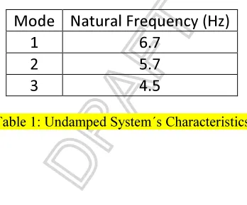
platform. Table 1 contains information relevant to the system´s characteristics:
Mode Natural Frequency (Hz)
1 6.7
2 5.7
[image:14.595.212.386.356.500.2]3 4.5
Table 1: Undamped System´s Characteristics
Since the purpose of this modelling is to test the behaviour of the camera under the
vibration effect transmitted from the fuselage, an input block for these vibrations needs
to be included. However, it should be noted that the methods used in this work are not
limited to a particular dynamic platform, as it will be shown on the following section,
the control algorithm is devised from a set of input vibration signals and output
vibration signals.
The chosen method in order to decrease the vibration on the vision system is a
semi-active approach technique; in particular, a spring-damper system is used where the
damping coefficient value is a time-dependant, C(t). This time dependency allows for an
adaptive damping method as the transmitted vibrations to the platform change with
time. This method requires an external agent that produces the change of the damping
variable C(t). An intelligent system that provides the adequate values for each situation
has been designed for this purpose. For the control method design, we need to take into
account that the performance of the semi-active device depends on the type of vibration
to be damped, therefore it is reasonable to use the vibration frequencies appearing on the
helicopter fuselage as inputs. In this paper, thefrequency of vibration in the gravity axis
(fz) and frequency of vibration in the perpendicular axis (fy) have been specifically
considered.
Prior to the design of the intelligent control algorithm, it is necessary to generate a
look up table containing the most adequate values for the spring stiffness (K) and the
damping coefficient (C) for each vibration. Considering these dependencies, an iterative
process was carried out where the damping and spring values were modified for each
combination of vibration in the gravity axis and in the perpendicular axis. That is,
mono-frequency vibrations have been used for each axis.
With the aim of deciding the most suitable values, a criterion function has been
has been defined such that the displacement of the camera around the equilibrium
position is decreased. In this paper, the standard deviation is used to evaluate the
camera´s undesired oscillations. Due to the fact that the mean is zero and since the
equilibrium position of the camera is located at the origin, the standard deviation shows
the camera´s displacement with respect to this position. By this method, we prevent a
minimum local to be chosen; it allows for a more accurate study disregarding the
unwanted peaks. Equation (1) shows the standard deviation expression, xi are the
camera displacement values, N is the number of data inside each window and µ is the
mean value.
=
∑ (−)
(1)
Therefore, the criterion function is directly linked to the performance of the control
system. Note that the values that minimize the vibration over the camera for each
combination of frequencies are chosen. In this way, once the iterative process has been
finished it is possible to obtain the damping and spring values which minimize the
criterion function for each type of vibration. At this stage, a table with the most
adequate K and C values for each vibration is generated. From now on, this table will be
known as “reference table”. At this point it is convenient to note that only
In the reference table, the K value that minimizes the criterion function for the level
of vibration produced by the helicopter shows very small variations, therefore it has
been decided for this value to remain constant. Therefore, the damping value C will be
the only parameter to be modified.
Once the reference table is obtained with the minimum values for the criterion
function, it is necessary to design an intelligent system that is able to provide the most
adequate values for each situation. This is, the reference table works as a data base in
order to train an intelligent system. This system should be able to learn and to provide
an output when confronted to an unknown input. Because of this, artificial intelligence
techniques based on a training set seem to be a good choice. One suitable option could
be the use of Neural Networks (Kosko, 1992), (Pajares, 2006), as their learning
properties are adequate for the problem undertaken. However, determining exactly why
it makes a particular decision is a daunting task because it is essentially a “black box”
and it makes this approach less attractive. In this paper a Neuro-Fuzzy approach based
on the scheme proposed by Jang (Jang, 1993), (Mitra, 2000), (Marichal et al. 2001) has
been used. These types of methods are known as Adaptive Neuro-Fuzzy Inference
Systems (ANFIS systems). In this framework, a neuro-adaptive learning method has
been used. That is, a given input/output data set has been used as first step to build a
Fuzzy inference system (FIS) (Zadeh, 1989), (Guijarro et al. 2009). In this paper the
is [fy fz K].It is a method that interprets the values in the input vector based on a set of
rules and assigns values to the output vector. Specifically the output of this system
provides the damping value. This involves the choice of the membership functions and
fuzzy logics operators, the design of fuzzy rules, the choice of the aggregation
mechanism, the involvement of the fuzzy rules (inference mechanism), and finally, the
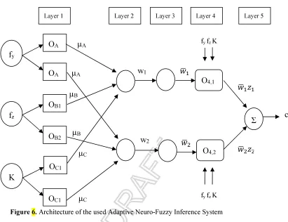
defuzzification method for obtaining a numeric output. Figure 6 shows the used ANFIS
architecture.
The steps to generate the initial Fuzzy Inference system are as follows:
• The first step is to take the inputs and determine the membership degree values
to each of the appropriate fuzzy sets via membership functions. The input is always a
crisp numerical value and the output is a fuzzy degree of membership within the interval
[0,1]. In this paper Gaussian membership functions have been used, determined by two
parameters known as premise parameters.
• The fuzzy operator is applied and a number is obtained that represents the result
of the antecedent for that rule.
• The Implication method is applied to a single number given by the antecedent,
and the output is a fuzzy set represented by a membership function, which weight is a
• The aggregation consists of the fuzzy sets that represent the outputs of each rule
are combined into a single fuzzy set. The input of this process is the list of fuzzy sets
that represent the outputs of each rule, and the output is a fuzzy set.
• The defuzzification process is applied, that is, the fuzzy set resulting from the
process of aggregation, becomes as a number. In this paper, this process is done by
weighted average as follows:
C = ∑ ొ సభ
∑ొసభ
(2)
Where C is the damping value given as system output, zi is the output of each rule, wi
Figure 6. Architecture of the used Adaptive Neuro-Fuzzy Inference System
The ANFIS architecture (http://www.mathworks.com/products/fuzzylogic) has been
used because it is a hybrid neural network. In our case, it has five layers, where only the
layers 1 and 4 are formed by adaptive nodes. That is, they have associated parameters
and they can change during the training phase. The explanation of what happens in each
layer is shown below. As it was said previously the system has three inputs (fy fz K)
each one with two membership functions, µAi y µBj, respectively, and an output C.
Hence, this system is associated to two fuzzy if-then rules of Takagi-Sugeno type which
are: OA fy fz µA µA µB µB OA OB1 w1
OB2 w
2
Σ
fy fz K
c O4,1 O4,2 Layer 1 K OC1 OC1 µC
µC fy fz K
If fy is µA1 and fz is µB1 and K is µC1 then z1= p1fy + q1 fz + r1K+s1 (3a)
If fy is µA2 and fz is µB2 and K is µC1 then z2= p2fy + q2 fz + r2K+s2 (3b)
Where , ,, are the consequent parameters.
On the first layer, each node has an output defined as:
Ο, = μ (4)
Ο, = () (5)
Ο, =() , i= 1,…,n (6)
Where n is the number of membership functions of the inputs, two in this case and it
is assumed that the three inputs have the same number of membership functions.
The second layer multiplies the input signals and each output of a node β
corresponds to the consequent for each rule. Note that, it represents the weight of the
conclusion of each rule.
= μ()(), i= 1,...,n; (7)
In the third layer, the output of each node Ω corresponds to the standard weights
=
∑సభ
, i= 1,…n (8)
The fourth layer calculates the output as a sum of the previous ones.
Finally, the fifth one adds all outputs of the fourth layer and it gives as output a real
number corresponding to damping value:
=∑ , i=1,…,n ; (10)
So far, a detailed description of the ANFIS structure has been presented. However in
order to get the final ANFIS system, it is necessary to devise a selection method for
parameter values.
To summarize, it can be said that the neuro-fuzzy modelling type ANFIS can be
divided into three main phases: to collect input/output data in the right so it can be used
by ANFIS for training, the creation of a Fuzzy System as initial structure and, the
application of a learning algorithm consisting of a combination of the least-squares
method and the backpropagation gradient descent method for training the ANFIS
parameters. It is important to remark that these parameters are the premise and
consequent parameters.
Once the method has been chosen, the ANFIS should be trained. For this purpose,
the reference table obtained has been divided into two groups; the eighty percent of the
data for the training phase and the rest of them to evaluate the generalization capability
of the ANFIS system. The inputs training data consist of a vector containing both
frequencies and the K value these minimize the movement over the camera [fy fz Kmin].
An additional component is necessary for the training data, and it is the desired output
indicated by the input vector. Once the ANFIS has been trained, the rest of the data are
used to validate the ANFIS system.
The trained ANFIS system is incorporated to the simulation environment in the form
of a block. This block requires as input the spring value and the frequencies of the
vibration signals. As the vibration signals have particular spectral characteristics, the
frequencies are determined by specific blocks introduced between the fuselage vibration
signal and the ANFIS block. These blocks are in charge of performing the Fast Fourier
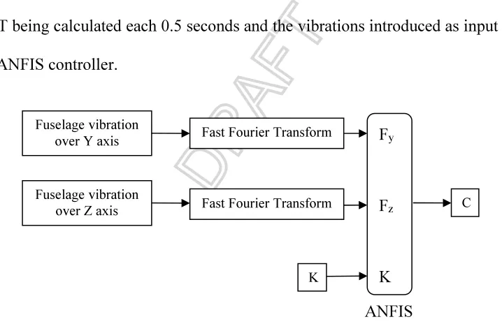
Transform (FFT) to obtain the dominant frequencies of the input signal. Figure 8 shows
the FFT being calculated each 0.5 seconds and the vibrations introduced as input signals
in the ANFIS controller.
Figure 8. ANFIS controller with the adequate c value for each combination of k value and frequencies
values as inputs
The next step is be to introduce the semi-active control system in the simulation
platform where C value is obtained by the ANFIS. The damper value changes every 0.5
Fuselage vibration over Y axis
Fuselage vibration over Z axis
Fast Fourier Transform
Fast Fourier Transform
Fy
Fz
K
K
ANFIS
[image:23.595.118.477.351.583.2]seconds and as it has been explained; it depends on the type of vibration for each case.
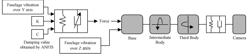
Figure 9 shows the intelligent vibration isolation system located between the point
[image:24.595.94.504.236.326.2]where the fuselage vibrations are received and the first body of the dynamic platform.
Figure 9. Intelligent vibration isolation system (grey boxes) positioned in order to reduce the vibrations.
Results
Once the semi-active isolation system and the intelligent controller have been
included in the simulation platform, the vibrations from the helicopter are introduced in
two blocks, one for each axis, as shown in Figure 8. Several simulations were carried
out in order to study how the vibration affects the camera.
First, a vibration of 1.3 millimetres amplitude in the Y axis and in the Z axis is
introduced on the vision system. It is necessary to emphasize at this point that these
signals are obtained by the helicopter simulation platform presented in section 2. In
order to check if the work presented in this paper improves the images captured by the
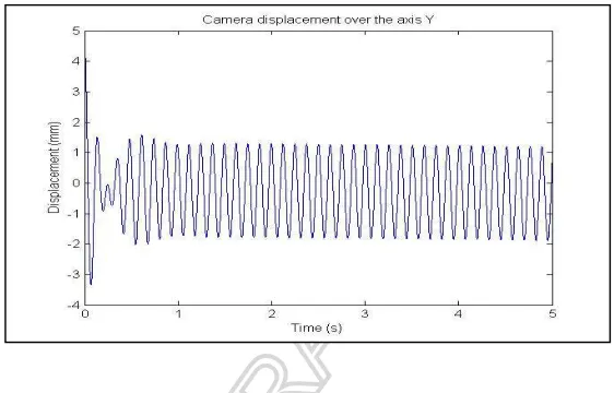
camera; the camera movement is compared for each technique. In Figure 10 it can be
seem appears the vibration suffered by the camera on the Y axis if the system does not
have any isolation device installed. As it can be observed, at the very beginning the Damping value
obtained by ANFIS
Camera Third Body Intermediate Body Base Force Fuselage vibration
over Y axis
Fuselage vibration over Z axis
K
signal suffers a moderated amplitude increase followed by a strong decrease, and before
0.5 seconds, its amplitude reaches values over 1.5 mm. The reason for this is the lack of
an isolation system; therefore the camera will oscillate following the input vibrations
[image:25.595.157.438.263.443.2]generated by the helicopter model.
Figure 10. Vibration of the camera on the Y axis when no isolation system is implemented
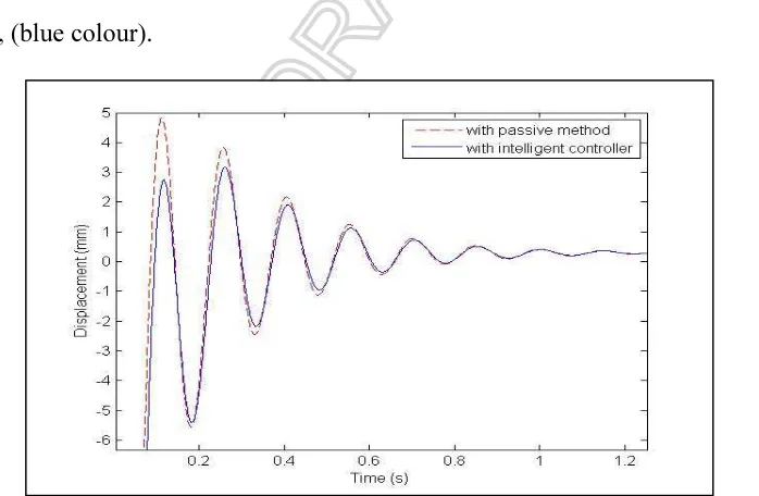
Figure 11 shows a comparison of the camera behaviour if the isolation method is
passive (constant spring and damping values); or if the proposed method with the C
values chosen by ANFIS system is applied. It is important to remark that the proposed
method sets new C values every 0.5 seconds and the K value is fixed to 10 N/m in both
Figure 11. Comparison of vibrations in the Y axis when a passive method is used or with the proposed
technique.
As it can be appreciated, after 1 second both methods perform equally, both signals
converge towards the set point. Analyzing the results it is concluded that a semi-active
method is better than a passive on the first 0.5 seconds. The proposed semi-active
method reduces the overshoot of the vibrations suffered by the camera. This presents a
substantial improvement on the vision system because the camera is kept recording
continuously and in this way, more stable images can be obtained.
A second simulation with a new vibration signal from the helicopter was carried out.
In this case, the introduced vibrations have lower amplitude in comparison with the
previous one; however, its spectral composition of frequencies is wider. Figure 12
shows the dominant frequencies chosen by the FFT block for the case of the axis Z
Figure 12. Dominant frequencies on the Z axis calculated each 0.5 seconds
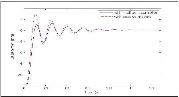
Figure 13 shows the camera displacement in the Z axis in two cases: when a passive
isolation method is used shown in (red colour) and the proposed semi-active method
[image:27.595.128.477.426.654.2]response, (blue colour).
Analyzing this result, it is seem once more that the proposed technique provides
better behaviour over the first interval of time, in comparison with the traditional
passive method. In this case, the vibrations cause a lower overshoot in the camera
displacement in comparison to the previous results.
Conclusions
A dynamic platform with a camera and a helicopter model has been designed in
Vehiclesim and Simulink/Simmechanics. This model allows studying the vibration
effects produced by the helicopter over the vision system. These vibrations influence
negatively on the quality of captured images because of the camera undesirable
movements. This problem expresses the need for a control system that could reduce this
negative influence.
In this paper an intelligent control strategy based on an ANFIS system has been
proposed. Several trials have been done. The applied strategy has allowed improving the
traditional passive and semi-active isolation techniques, particularly at the beginning of
the vibration, during the first tenths of second. In this way a reduction in the highest
peaks is achieved by low energy actions, providing a more stable vision system. The
developed technique could be implemented using several semi-active actuators. In this
sense, it should be pointed out that there are different current technical possibilities for
semi-active device implementation such as electrorheological, magnetorheological,
The presented method provides improved images captured with a lower level of
vibrations, making easier any subsequent image processing. In fact, it is important to
point out that the methods used in this paper are not strongly linked to any particular
platform configuration.
Acknowledgements
This work has been supported by the Spanish Government DPI2010-20751 and
DPI2010-20751-C02-02 of Ministerio de Ciencia e Innovación and by the grant of the
Agencia Canaria de Investigación, Innovación y Sociedad de la Información del
Gobierno de Canarias, cofinanced with the European Social fund.
References
Alanoly J, Sankar S, A new concept in semi-active vibration isolation, American
Society of Mechanical Engineers, Journal of Mechanisms, Transmissions, and
Automation in Design 109 (1987) 242–247.
Bittanti S and Lovera M, On the zero dynamics of helicopter rotor loads, European J.
Contr., 2, 1,5768, 1996.
Decker WA, Talbot PD, Tinling BE and Chen RTN. A mathematical model of a single
main rotor helicopter for piloted simulation. Technical memorandum NASA 84281,
Garrad W, and Low E. Eigenspace design of helicopter flight control systems. Technical
report, Dept. of Aerospace Engineering and Mechanics, Univ. of Minnesota, 1990.
Guijarro M, Pajares G. On combining classifiers through a fuzzy Multicriteria Decision
Making Approach: applied to natural textured images. Expert Syst. Appl. 2009, 36,
7262-7269.
Heffley RK and Mnich MA. Minimum complexity helicopter simulation math model.
Contractor report NASA 177476. Aeroflight dynamics Directorate, U.S. Army Research
and Tecnology Activity (AVSCOM), April 1988
http://avia.russian.ee
http://www.carsim.com/
Jang JR. ANFIS: Adaptive-network-based fuzzy inference system. IEEE Trans. Syst.
Man Cybern. 1993, 23, 665-685
Jansen LM, Dyke SJ, Semi-active control strategies for MR dampers: a comparative
study, American Society of Civil Engineers, Journal of Engineering Mechanics 126 (8)
(1999) 795–803.
Johnson W, Helicopter Theory. Princeton, NJ: Princeton Univ. Press,1980.
Kaloust J, Ham C and Qu Z. Nonlinear autopilot control design for a 2-DOF helicopter
Karnopp DC, Crosby MJ, Harwood RA, Vibration control using semi-active force
generators, American Society of Mechanical Engineers, Journal of Engineering for
Industry 96 (2) (1974) 619–626.
Kienitz K, Wu Q and Mansour M. Robust stabilization of a helicopter model.
Proceedings of the 29th CDC, 1990, 2607 −2612.
Kosko B. Neural Networks and Fuzzy Systems: A Dynamical Systems Approach to
Machine Intelligence, Prentice-Hall, Englewood Cliffs, NJ (1992).
Marichal GN, Acosta L, Moreno L, Mendez JA, Rodrigo JJ, ,Sigut M. Obstacle
avoidance for a mobile robot: a neuro fuzzy approach. Fuzzy Sets and Systems. 2001,
vol. 124, pp. 171-179
MathWorks. Matlab. Available online: http://www.mathworks.com/products/fuzzylogic
(accessed on November 12, 2009).
Miller LR, Tuning passive, semi-active, and fully active suspension systems, in:
Proceeding of the 27th Conference on Decision and Control, Austin, TX, 1988.
Mitra S, Hayashi S. Neuro-fuzzy rule generation: Survey in soft computing framework.
IEEE Trans. Neural Netw. 2000, 11, 748-768
Mousseau CW, Sayers MW and Fagan D J, Symbolic quasistatic and dynamic analyses
of complex automobile models, The Dynamics of Vehicles on Roads and on Railway
Narramore JC, Computational fluid dynamics development and validation at Bell
Helicopter. Textron Bell Helicopter, Fort Worth, TX.In AGARD, Aerodynamics and
Aeroacoustics of Rotorcraft 13, (SEE N96-13582 02-01), 1995.
Padfield GD. Helicopter flight dynamics: the theory and application of flying qualities
and simulation modelling. Oxford: Blackwell, 1996
Pajares G. A Hopfield Neural Network for Image Change Detection. IEEE Trans.
Neural Netw. 2006, 17, 1250-1264
Rakheja S, Sankar S, Effectiveness of ‘‘on–off’’ damper in isolation dynamical systems.
Shock and Vibration Bulletin 57 (1986) 147–156.
Rakheja S, Sankar S, Vibration and shock isolation performance of a semi-active ‘‘on–
off’’ damper, American Society of Mechanical Engineers, Journal of Vibration,
Acoustics, Stress, and Reliability in Design 107 (1985) 398–403.
Sayers MW (1999) Vehicle models for RTS applications. Vehicle System Dynamics
32(4-5): 421-438
Sharp RS, Evangelou S and Limebeer DJN, Advances in the modeling of motorcycle
dynamics, Multibody System Dynamics 12(3), 2004, 251-283
Sharp RS, Evangelou S and Limebeer DJN, Multibody aspects of motorcycle
modelling with special reference to Autosim, Advances in Computational Multibody
Systems, J. G. Ambrósio (Ed.), Springer- Verlag, Dordrecht, The Netherlands, 2005,
Simulink ® Available online http://www.mathworks.com/products/simulink/
Steele Jr. and Guy L. COMMON LISP: The language. Digital Press. Burlington, Mass,
1984
Tomás-Rodríguez M, Sharp R, Automated Modeling of Rotorcraft Dynamics with
Special Reference to Autosim, Automation Science and Engineering, 2007. CASE
2007. IEEE International Conference, 2007, Pages: 974-979
Tomás-Rodríguez M. “Helicopter rotor dynamics modelling”, MPhil Thesis, Imperial
College, 2008.
Verdult V, Lovera M and Verhaegen M. Identification of linear parameter-varying
state-space models with application to helicopter rotor dynamics, International Journal of
Control, 77, 13, Sep 2004, 1149 - 1159.
Wu X, Griffin MJ, A semi-active control policy to reduce the occurrence and severity of
end-stop impacts in a suspension seat with an electrorheological fluid damper, Journal
of Sound and Vibration 203 (5) (1997) 781–793.
Zadeh LA. Knowledge representation in fuzzy logic. IEEE Trans. Knowl. Data Engin.