1
Motion Analysis of a Foldable Barrel Vault
Based on Regular and Irregular Yoshimura
Origami
Cai Jianguo1
Key Lab. of C & PC Structures of Ministry of Education, National Prestress Engineering Research Center, Southeast University
Si Pai Lou 2#, Nanjing, China e-mail: [email protected] ASME Member
Deng Xiaowei
Department of Structural Engineering, University of California, San Diego, USA e-mail: [email protected]
Xu Yixiang
Department of Civil Engineering, Strathclyde University, Glasgow G12 8QQ, United
Kingdom
e-mail: [email protected] Feng Jian
Key Lab. of C & PC Structures of Ministry of Education, National Prestress Engineering Research Center, Southeast University
e-mail: [email protected] ABSTRACT
This paper investigates the geometry of a foldable barrel vault with Yoshimura Origami patterns during
the motion. On the base of the geometry analysis of the origami unit, the radius, span, rise, and
longitudinal length of the foldable barrel vault with regular Yoshimura Origami pattern in all
configurations throughout the motion are determined. The results show that the radius of curvature and
the span increase during deployment. But the rise increases first, followed by a decrease with increasing
fold angle. Furthermore, the influence of the apex angle of the origami unit and the numbers of triangular
2
plates in the span direction on the geometric parameters is also investigated. Finally, the method to obtain
the rise and span of the barrel vault with irregular origami pattern is also given.
INTRODUCTION
Deployable structures have the ability to transform themselves from a small, closed or stowed configuration to a much larger, open or deployed configuration [1, 2]. Large aerospace structures, e.g. antennas and masts, are prime examples of deployable structures. Due to their size, they often need to be packaged for transportation and expanded at the time of operation [3]. On the other hand, temporary accommodation, or specially tents, is also one of the applications of deployable structures [4]. The
deployment of most of such structures relies on the concept of mechanisms, i.e. the structures are assemblies of mechanisms whose mobility is retained for the purpose of deployment.
Origami, the Japanese and Chinese traditional paper craft, has been proved as a valuable tool to develop various engineering applications in numerous fields [5-7]. Several designs of origami structures have been proposed for deployable structures from around 1970s, such as the Miura-ori, which is a well-known rigid origami structure utilized in the packaging of deployable solar panels for use in space or in the folding of maps [8]. Cai et al. [9] have investigated the geometry and motion of a deployable shelter structures based on Miura-ori. Moreover, the geometry of a foldable barrel vault with modified Miura-ori patterns, which displays a curvature change during the motion, was also studied by Cai et al. [10].
post-3 buckling behavior of a thin cylindrical shell under axial loading. A family of foldable, portable structures, based on the Yoshimura origami pattern, has been presented by Foster and Krishnakumar [14]. These structures have considerable shape flexibility (multiple degrees of freedom), but once erected they possess significant stiffness. These foldable plate structures consist of a series of triangular plates, connected at their edges by continuous joints, allowing each plate to rotate relative to its neighboring plate. The plates can fold into a flat stack and unfold into a predetermined three-dimensional configuration, with a corrugated surface. Tonon [15, 16] has further expanded this concept to study the geometry of single and double curvature foldable plate structures, such as domes, conics, paraboloids and hyperboloids. Although they are compactly foldable into a compact stack of plates, some fold patterns cannot be developed in a plane, as opposed to the configurations previously given by Foster.
4 all configurations throughout the motion, which are very important to the design of the system, are obtained.
GEOMETRY ANALYSIS OF A YOSHIMURA ORIGAMI UNIT
Geometry description
Figure 2 shows a Yoshimura origami unit, the basic origami pattern with six creases, where the continuous lines indicate mountain folds while the dotted lines indicate valley folds. Figure 2 (a) demonstrates the fully unfolded configuration which is also the planar state of the basic unit and Fig. 2(b) demonstrates the partly foldable configuration. Fig. 2 Basic origami unit with six creases
Angle β between the mountain fold line and the valley fold line is defined as the apex angle of the basic origami unit. Define angle θ as the fold angle between the rigid plate with shade lines of the unit in Fig. 2(b) and the vertical plane, which is 0° in the fully foldable state and 90° in the fully unfolded state. It can be seen that the apex angle of the unit is a constant during the deployment of the origami, but its projections on the horizontal and vertical planes are changing.
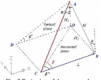
Projection of the apex angle
The projection of the apex angle on the horizontal and vertical planes during the motion is shown in Fig. 3. The projection of the apex angle on the vertical plane is β′, and on the horizontal plane is β′′.
In the right triangle⊿ABC of Fig.3, there is
tan
HL (1) In the right triangle⊿OAB, there is
1 cos
5 In the right triangle⊿OAD, there is
1 tan '
H L (3) Substituting Eqs. (1) and (2) into Eq. (3) leads to the projection of the apex angle on the vertical plane
tan'tancos (4) Similarly, in the right triangle⊿OAB, there is
2 sin
H H (5)
In the right triangle⊿OBC, there is
2 tan ''
H L (6) Substituting Eqs. (1) and (5) into Eq. (6) leads to the projection of the apex angle on the horizontal plane is:
tan''tansin (7) MOTION ANALYSIS OF THE FOLDABLE BARREL VAULT
Foldable barrel vault
The origami pattern for the foldable barrel vault, in which the basic origami units are arranged separately in the longitudinal and span direction, is given in Fig.4. The basic units of this pattern are marked by red rectangles in the figure. The structure can also be seen as composed of a series of triangular plates connected by continuous joints, allowing each plate to rotate around the intersection lines. Assume that the number of triangular plates in the span direction is p, the column number in the longitudinal direction is m. Therefore, in Fig.4, p is 7 and m is 4.
Apex angles of the basic units in Fig.4 separately are β1, β2, β3, β4, β5 and β6,
6 situation that all origami unit with equal apex angles while the unequal apex angles situation will be considered in the next section.
Analysis of the movement process
Figure 5 shows the top view of the barrel vault in the fully unfolded state and the section view in the partly foldable state. Fig. 5(b) reveals the vertical projections of the apex angle of the basic origami units, where the connecting line of vertices of each triangle plate is a circular arc. The central angle of this arc is
2(p 1) '
(8)
The length of its radius is
sin 2 'L R
(9)
where L is length of the basic triangle plate.
In Fig. 5(b), the span of the barrel vault during the motion can be obtained as
2 sin 2
S R (10)
Substituting Eqs. (8) and (9) into Eq. (10) leads to
2 sin 1 '
sin 2 ' L
S p
(11)
And the rise of the barrel vault during the motion is
cos2
1 cos 1 '
sin 2 ' H R R
L p
(12)
The width of the basic units in the longitudinal direction is
tan '' tan sin
7 Therefore, the width of the barrel vault in the longitudinal direction during the motion is
tan sin
WmwmL (14) Now the basis geometry parameter of the structure is assumed as p=7, m=4, β=30°. During the motion, the fold angle θ is an independent variable. Therefore, the radius, span, rise and width of the structure during the motion can be investigated as follows.
The relationships between the radius and the fold angle θ are given in Fig. 6. From this figure, it can be found that with the continuous deployment of the model and the value of θ increasingfrom 0° to 90°, the radius increases continuously from the initial value R0 and trends to infinity when the structure approaches to the fully unfolded
configuration. Moreover, when the fold angle θ is small, the radius changes slightly. But when θ is close to 90°, the radius increases exponentially. With Eqs. (4) and (9), the initial value of the radius can be obtained as
0
2
3 L
R (15)
Figure 7 shows the relation between the span and the fold angle θ. When the motion from the folded configuration to the deployment configuration, the span S increases
continuously and approaches to S0=(p-1)L until the fully unfolded state of the system.
Due to the case of p=7, the span in the fully deployable state is 6L.
As shown in Fig. 8, with the increase of the fold angle θ, the rise of the barrel vault experiences two stages of variations, i.e., first increase to the maximum and then decrease to 0. In the first stage, the rise increases to the maximum and has a small range of
8 Figure 9 shows the longitudinal length of the barrel vault during the deployment. In the fully foldable state, the initial value of the longitudinal length is 0, and then changes linearly. When θ is close to 90°, the variation rate of the longitudinal length becomes extremely slow and the value approaches to mLtanβ in the fully deployable state. PARAMETRIC ANALYSIS
The influence of the apex angle β of the origami unit and the number of triangular plates p in the span direction on the radius, span, rise, longitudinal length of the barrel vault will be studied in this section.
Influence of the apex angle
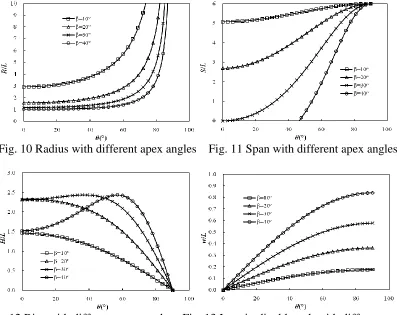
The apex angle is an important factor that affects the kinematic behavior of systems. The radius, span, rise and the longitudinal length during the motion with different apex angles are shown in Figs. 10 to13 where four apex angles, 10°, 20°, 30° and 40°, are considered in this study.
As shown in Fig.10, with different apex angles β, the relationships between the radius and the fold angle θ are similar. The radiuses all increase continuously with the deployment of the system. It can also be found from Fig. 10 that the radius decreases with the increase of the apex angle β in the fully foldable state. Moreover, during the motion with the same fold angle θ, the radius decreases with the increase of β as well.
9 allowable in the physical structures, which leads to a certain limit in the range of fold angle θ. From the figure, the four curves present the same change rules with the deployment of the system, but with the increase of the apex angle β, the variation amplitude of span is more obvious.
The effect of the apex angle β on the rise is shown in Fig.12. When β is 30° or 40°, the rise of the model experiences the process of increasing first and then decreasing to 0 with the increase of fold angle θ. When β is 10° or 20°, the rise decreases continuously with the deployment of the model. And the rises of all models are 0 in the fully
deployable state. The rises are 1.46L, 2.33L, 2.31L, 1.52L corresponding to the apex angles are10°, 20°, 30° and 40° in the fully foldable state. It should be noted that when β is 40°, the fold angle θ can not be 0 which also means insignificance of the corresponding rise. When β is 30°, in the fully foldable state, the central angle is just 360° and the rise is 2R or 2.31 L.
Figure 13 shows the effect of apex angles β on the longitudinal length. As shown in the figure, the variation trends of all curves are similar. The longitudinal lengths increase continuously with the increase of the fold angle θ. The longitudinal lengths of all models are 0 in the fully folded state and are mLtanβ in the fully deployable state.
Influence of the number of triangular plates
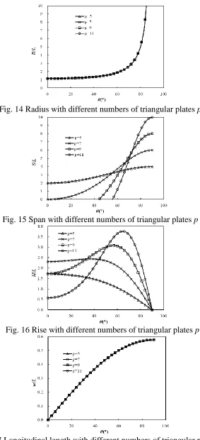
The geometry parameters of the barrel vault with different numbers of triangular plates during the motion are shown in Figs. 14-17. The numbers of triangular plates correspond to 5, 7, 9 and 11, respectively.
10 with different numbers of triangular plates p are shown in Fig. 15. It can be seen that the four curves present the same change trends with the deployment of the system. The span increases with the increase of the fold angle. Moreover, with the increase of the number of triangular plates p, the change in range of the curves is more obvious. It should be noted that when the fold angle is small, the value of span may be negative for the system with p=9 or 11. It means that the units “penetrate” through each other, which leads to a limit deployment range of a physical structure.
The effect of the number of triangular plates p on the rise is shown in Fig. 16.When numbers of triangular plates p are 7, 9 and 11, the rises of the barrel vault experience the process of increasing first and then decreasing to 0 with the increase of fold angle θ. When p is 5, the rise decreases continuously with the deployment of the barrel. And the rises of all models are 0 in the fully deployable state. The rises are 1.73L, 2.31L, 1.73L, 0.58L corresponding to the number of triangular plates p are 5, 7, 9 and 11 in the fully foldable state. It needs to point out that when p is 9 or 11, the fold angle θ cannot be 0 which also means insignificance of the corresponding rise. Figure 17 shows the relation between longitudinal length and the fold angle θ with different numbers of triangular plates p. It can be found that the number of triangular plates p has no effect on the longitudinal length w of the system.
MOVEMENT BOUNDARY
11 angle θ when the model cannot be folded, will be studied. From Eq. (8), the central angle is 360° which can be given as
2(p1) ' 2 (16) which leads to
' 1 p
(17)
Substituting Eq. (17) into Eq. (4) leads to
tan tan cos
1 p
(18)
Therefore, the critical value of the fold angle θ is
tan 1 arccos tan l p
(19)
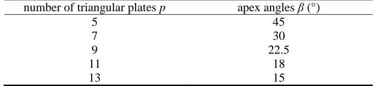
Now considering a special case, when the system is fully folded or the critical value of the fold angle θ is 0, the central angle is 360°. Substituting θ = 0 into Eq. (19) to obtain the apex angle as
1 p
(20)
12 can be calculated with Eq. (19). Figure 18 shows the relationship between the critical value of the fold angle and the apex angle β. It can be seen from this figure that the critical value of the fold angle increases with the increase of the apex angle. That is to say the foldable range of the barrel vault also decreases with the increase of the apex angle. Moreover, when the apex angle of the basic unit is close to the value given in Eq. (20), the critical value of the fold angle θ changes significantly.
MOTION ANALYSIS OF THE BARREL VAULT WITH IRREGULAR PATTERNS
The structures discussed above are all based on the regular Yoshimura origami pattern, which have consistent geometric parameters of every origami unit. In Section 2, we have mentioned that the connecting line of vertices of triangle plates is a circular arc in the partly deployable state as shown in Fig. 5(b). If the connecting line of these vertices constitutes an ellipse or parabola, the system has a larger interior space with the same rise of the system.
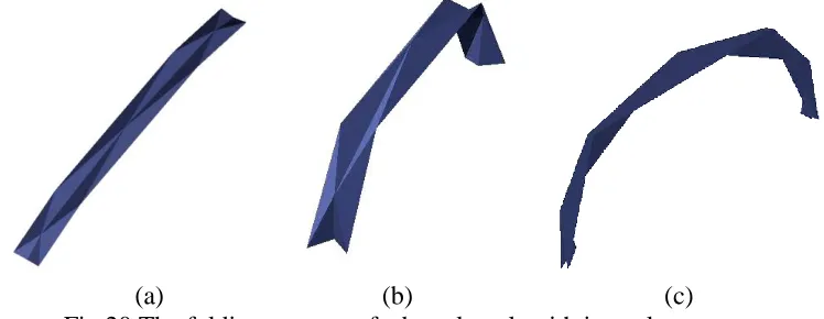
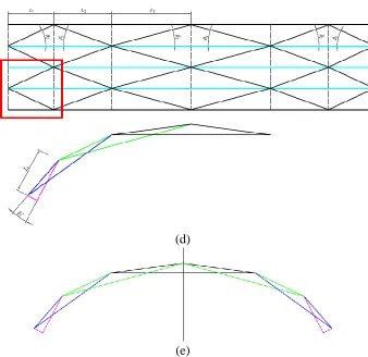
Figure 19 shows an origami pattern with irregular units. But the system also has symmetry of the central line. The connecting line of vertices of triangle plates is an ellipse in the partly deployable state. The folding process of this foldable plate structure is shown in Fig. 20. A graphing method is used to obtain the side projection of the barrel vault during the motion. The steps are shown in Fig. 21. The side projections from the central Yoshimura origami unit to the boundary Yoshimura origami unit are given in from Fig. 21 (a) to Fig. 21(d), where the rectangular with red color shows the basic Yoshimura origami unit. Finally, the side projection of the whole barrel vault is given in Fig. 21(e).
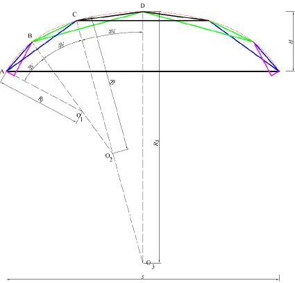
The rise and span of the barrel vault with irregular origami units is given in Fig. 22.
13
sin sin sin
AC AB BC
ABC ACB BAC
(21)
As shown in Fig. 21, the length of AC is L1+ L2, thus the lengths of AB and BC are
1 2 2
1 2
1 2 1
1 2
sin '
sin ' '
sin '
sin ' ' L L AB L L BC (22)
In the isosceles triangle⊿O1AB, the length of R1 is
1 2
21 1
1 1 2 1
sin ' 2sin ' 2sin ' ' sin '
L L AB
R O A
(23)
In the isosceles triangle⊿O2BC, the length of R2 is
1 2
12 2
2 1 2 2
sin '
2sin ' 2sin ' ' sin ' L L
BC
R O B
(24)
In⊿BCD, we have
sin sin
CD BD
DBC DCB
(25)
As shown in Fig. 21, the length of BD is L2+ L3, thus the length of CD is
2 3 2
2 3
sin '
sin ' ' L L
CD
(26)
In the isosceles triangle⊿O3CD, the length of R3 is
2 3
23 3
3 2 3 3
sin '
2sin ' 2sin ' ' sin ' L L
CD
R O C
(27)
As shown in Fig.22, when the lengths of R1,R2 and R3 are obtained, the rise H and
the span S can be easily calculated as
3 3 2 cos 2 3' 2 1 cos 2 3' 2 2' 1cos 2 3' 2 2' 2 1'
HR R R R R R
(28)
3 2 3 2 1 3 2 1 3 2 1
2 sin 2 ' sin 2 ' 2 ' sin 2 ' 2 ' 2 '
S R R R R R
14 It should be noted that Eqs. (28) and (29) can only be applied to the symmetric patterns with p=7, whose connecting lines of these vertices of the triangle plates
constitutes an ellipse. However, the graphing method given in this paper can also be used to study the shape or geometric parameters of the foldable structures with other irregular origami patterns.
CONCLUSIONS
The geometric parameters of a foldable barrel vault based on regular and non-regular Yoshimura origami patterns during the motion are studied in this paper.
Normally, in the design of a foldable barrel vault, the designer will give the span and rise of the barrel vault when the system is under the external loads. Moreover, for a foldable structure, the volume in the fully folded configuration is also very important. Then when these parameters are known, the method given in this paper can be used to study the number of the triangle plates and the geometry of a single triangle plate. Furthermore, the deployment angle of the state when the system is under the external loads (such as the dead load, wind load or snow load etc.) can also be found. From the analysis, we can draw the following conclusions.
(1) With the deployment of the model, the radius increases gradually and at the beginning shows little change but then increases exponentially. The slope of the span increase is relatively flat at the early and final stage and shows approximate linear growth in the medium stage. With the increase of the fold angle, the rise of the model
15 (2) With the increase of the apex angle β of the basic unit, the span decreases
continuously; on the contrary, the rise changes in the opposite direction, i.e., the rise increases obviously with the increase of the apex angle. And the fold angle corresponding to the maximum of the rise also increases with the increase of β.
(3) With the increase of the numbers of triangular plates p, the amplitude of the span increases sharply, but the change range of the fold angle decreases. The rise increases obviously with the increase of the number of triangular plates p and the fold angle corresponding to the maximum of the rise with the increase of p.
(4) The method to obtain the rise and span of the barrel vault with irregular origami pattern is also given.
ACKNOWLEDGMENTS
16 REFERENCES
[1]De Temmerman N. Design and Analysis of Deployable Bar Structures for Mobile Architectural Applications, Vrije Universiteit Brussel, Ph.D. thesis, 2007.
[2]Jensen F V. Concepts for retractable roof structures. University of Cambridge, Ph.D. thesis, 2004.
[3]Chen Y. Design of Structural Mechanisms, Oxford University, Ph.D. thesis, 2003.
[4]Khayyat H. Conceptual Design and Mechanisms for Foldable Pyramidal plated structures, Ph.D. thesis, University of Cardiff, 2008.
[5] Sorguc A G, Hagiwara I, Selcuk S A. “Origami in Architecture: A Medium of Inquiry for Design in Architecture”. Metu Jfa, 2009, 26(2): 235-247.
[6] Hagiwara I. “From Origami to Origamics”. Science Japan Journal, 2008, July, 22-25.
[7]Guest S D. Deployable structures: Concepts and Analysis. University of Cambridge, PhD thesis, 1996.
[8] Miura K. “Method of packaging and deployment of large membranes in space”, In:
Proceedings of 31st Congress of International Astronautics Federation (IAF-80-A31), Tokyo, Japan, 1980, 1-10.
[9] Cai Jianguo, Deng Xiaowei, Xu Yixiang, Feng Jian. “Geometry and Motion Analysis of Origami-based Deployable Shelter Structures”, Journal of Structural Engineering ASCE, 2015, accepted
[10] Cai Jianguo, Xu Yixiang, Feng Jian. “Geometric Analysis of a Foldable Barrel Vault With Origami”, Journal of Mechanical Design ASME, 2013, 135, 114501
[11] Yoshimura Y. “On the mechanism of buckling of a circular cylindrical shell under axial compression and bending”, Reports of the Institute of Science and Technology of the University of Tokyo, 1951, (English translation: Technical Memorandum 1390 of the National Advisory Committee for Aeronautics, Washington DC, 1955).
[12] Hunt GW, Lord GJ, Peletier MA. “Cylindrical shell buckling: a characterization of localization and periodicity”, Discrete Contin. Dyn. Syst. B, 2003, 3 (4):505-518.
[13]Thompson JMT, Hunt GW. Elastic Instability Phenomena, Wiley, Chichester, 1984.
[14]Foster, C.G., Krishnakumar, S. “A Class of Transportable Demountable Structures”,
17
[15]Tonon, O. “Geometry of Spatial Folded Forms”, International Journal of Space Structures, 1991, 6(3), 227–240
[16]Tonon, O. Geometry of spatial structures 4, 1993, pp. 2042-2052, Thomas Telford, London.
[17] De Temmerman, N., Mollaert, M., Van Mele, T., De Laet, L., “Design and Analysis of a Foldable Mobile Shelter System”, International Journal of Space Structures, 2007, 22(3), 161-168
[18]Thrall A.P., Quaglia C.P. “Accordion shelters: A historical review of origami-like deployable shelters developed by the US military”, Engineering Structures, 2014, 59: 686-692
18 Figure Captions List
Fig. 1 The folding process of a barrel vault
Fig. 2 Basic origami unit with six creases (a) Fully unfolded configuration (b)
Partially foldable configuration
Fig. 3 Projection of the apex angle Fig. 4 Origami pattern for a barrel vault
Fig. 5 A barrel vault (a) Top view in the fully unfolded state (b) Cross section
in the partially foldable state
Fig. 6 Radius during the motion
Fig. 7 Span during the motion
Fig. 8 Variation of rise during motion
Fig. 9 Variation of longitudinal length during motion Fig. 10 Radius with different apex angles
Fig. 11 Span with different apex angles Fig. 12 Rise with different apex angles
19 Fig. 17 Longitudinal length with different numbers of triangular plates p
Fig. 18 Relationship between critical value of the fold angle and apex angle β Fig. 19 Origami pattern with irregular units
Fig. 20 The folding process of a barrel vault with irregular patterns Fig. 21 Side projection of the barrel vault during the motion
20 Table Caption List
21 (a) (b)
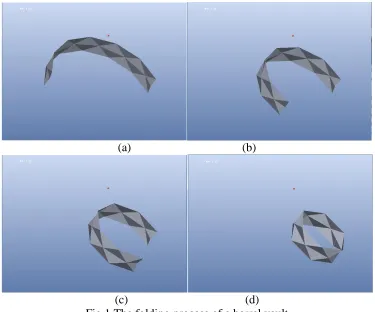
[image:21.612.119.494.70.382.2](c) (d) Fig.1 The folding process of a barrel vault
22 Fig. 3 Projection of the apex angle
Fig.4 Origami pattern for a barrel vault
(a) Top view in the fully unfolded state (b) Cross section in the partially foldable state Fig. 5 A barrel vault
[image:22.612.95.488.104.763.2][image:22.612.96.485.560.714.2]
23 Fig.8 Variation of rise during motion Fig.9 Variation of longitudinal length during
[image:23.612.108.505.255.570.2]motion
Fig. 10 Radius with different apex angles Fig. 11 Span with different apex angles
24 Fig. 14 Radius with different numbers of triangular plates p
Fig. 15 Span with different numbers of triangular plates p
Fig. 16 Rise with different numbers of triangular plates p
[image:24.612.167.444.366.682.2]25 Fig. 18 Relationship between critical value of the fold angle and apex angle β.
Fig. 19 Origami pattern with irregular units
[image:25.612.118.492.396.541.2]
26 (a)
(b)
27 (d)
[image:27.612.138.476.69.397.2](e)
29 Table 1 Relationship between number of triangular plates p and apex angle β
number of triangular plates p apex angles β (°)
5 45
7 30
9 22.5
11 18