City, University of London Institutional Repository
Citation
:
Mylonas, N. (2012). Development of positioning devices for MRI-guided high intensity focused ultrasound (HIFU) for abdominal, thyroid and brain, tumours. (Unpublished Doctoral thesis, City University London)This is the unspecified version of the paper.
This version of the publication may differ from the final published
version.
Permanent repository link: http://openaccess.city.ac.uk/2417/
Link to published version
:
Copyright and reuse:
City Research Online aims to make research
outputs of City, University of London available to a wider audience.
Copyright and Moral Rights remain with the author(s) and/or copyright
holders. URLs from City Research Online may be freely distributed and
linked to.
City Research Online: http://openaccess.city.ac.uk/ publications@city.ac.uk
Development of positioning devices for
MRI-guided high intensity focused
ultrasound (HIFU) for abdominal, thyroid
and brain, tumours
A thesis submitted to the graduate faculty in partial fulfilment of
the requirements for the Degree of Doctor of Philosophy in
Biomedical Engineering
Nicos Mylonas
School of Engineering and Mathematical Sciences
Electronic and Electrical Engineering
City University London
Table of Contents
LIST OF FIGURES ... IV LIST OF TABLES ... IX ABBREVIATIONS AND SYMBOLS USED ... XIV
1 INTRODUCTION ... 1
1.1 AIMS AND OBJECTIVES ... 3
1.2 CHAPTERS OUTLINE ... 4
2 ABDOMINAL AND THYROID TUMOURS ... 6
2.1 LIVER TUMOURS ... 6
2.1.1 Non-cancerous liver tumours ... 7
2.1.2 Cancerous liver tumours ... 7
2.1.3 Liver cancer statistics... 11
2.2 KIDNEY TUMOURS ... 11
2.2.1 Non-cancerous kidney tumours ... 12
2.2.2 Cancerous kidney tumours ... 14
2.2.3 Kidney cancer statistics ... 18
2.3 PANCREATIC TUMOURS ... 19
2.3.1 Pancreatic Cancers ... 20
2.3.2 Pancreatic cancer statistics ... 23
2.4 THYROID TUMOURS ... 24
2.4.1 Thyroid benign and malignant tumours ... 25
2.5 BRAIN TUMOURS ... 29
2.5.1 Benign and malignant and metastatic brain tumours ... 31
2.6 CONCLUSION ... 34
3 HIGH INTENSITY FOCUSED ULTRASOUND (HIFU) TECHNOLOGY ...35
3.1 ULTRASOUND THEORY AND ULTRASOUND TRANSDUCERS ... 35
3.2 HIFU TRANSDUCERS, PHYSICS AND TECHNOLOGY OF HIFU ... 37
3.3 UTILIZATION OF MRI FOR THE GUIDANCE OF THE THERAPEUTIC ULTRASOUND. ... 42
3.4 THERAPEUTIC ULTRASOUND AND HIFU ... 44
3.4.1 How HIFU can be used to treat tumours ... 45
3.4.2 MRI compatible HIFU Transducers and safety issues ... 46
3.5 HISTORY OF THERAPEUTIC HIFU ... 47
4 APPLICATIONS OF HIFU IN MEDICINE ...52
4.1 CURRENT STATE OF THE ART OF HIFU FOR TREATING ABDOMINAL TUMOURS AND THYROID TUMOURS ... 52
4.1.1 Disadvantages of the current methods for treating abdominal tumours ... 54
4.2 ADVANTAGES OF HIFU ... 55
4.3 LIMITATIONS AND DRAWBACKS OF HIFU ... 57
4.4 MAGNETIC RESONANCE GUIDED HIGH INTENSITY FOCUSED ULTRASOUNDS (MRGHIFU) SYSTEMS ... 57
4.5 IMAGE GUIDED ROBOTS AND HIFU SYSTEMS WITH MRI GUIDANCE ... 59
4.6 EXISTING IMAGING POSITIONING DEVICES ... 59
5 DEVELOPMENT OF HIFU SYSTEM WITH MRI GUIDANCE ...64
5.1 DESIGN CRITERIA AND REQUIREMENTS ... 64
5.2 HIFU/ MRI SYSTEM ... 65
5.2.1 HIFU system ... 65
5.2.2 Positioning device (Robot) ... 68
5.2.3 Cavitation detector ... 74
5.2.4 MRI compatible camera ... 74
5.2.5 Software ... 74
5.3 ADVANTAGES AND LIMITATIONS OF THE THREE VERSIONS OF POSITIONING DEVICES ... 75
6.1 DESCRIPTION OF THE POSITIONING DEVICE – 1ST
VERSION ... 78
6.2 DESIGN AND IMPLEMENTATION OF POSITIONING DEVICE VERSION 1 ... 79
6.2.1 Parts and materials used for the positioning device ... 80
6.2.2 Description of the operation of the positioning device... 86
6.2.3 Coupling mechanism ... 88
6.3 CONCLUSION AND DISCUSSION ... 89
7 DEVELOPMENT OF THE POSITIONING DEVICE VERSION 2 ...91
7.1 PARTS AND SPECIFICATIONS OF POSITIONING DEVICE VERSION 2 ... 92
7.2 DESIGN AND DEVELOPMENT OF THE 2ND VERSION OF THE POSITIONING DEVICE ... 93
7.3 CONCLUSION AND DISCUSSION ... 99
8 DEVELOPMENT OF THE POSITIONING DEVICE VERSION 3 ... 101
8.1 PARTS AND SPECIFICATIONS OF POSITIONING DEVICE VERSION 3 ... 102
8.2 DESIGN AND DEVELOPMENT OF THE 3RD VERSION OF THE POSITIONING DEVICE ... 103
8.3 CONCLUSION AND DISCUSSION ... 114
9 SOFTWARE AND PERIPHERAL DEVICES OF A HIFU SYSTEM DEVELOPMENT... 116
9.1 SOFTWARE DEVELOPMENT AND SETUP OF THE PERIPHERAL DEVICES USED FOR CAPTURING TEMPERATURE, PHOTOGRAPHS AND VIDEO DISPLAYED IN THE USER INTERFACE. ... 117
9.2 DEVELOPMENT OF THE DIGITAL THERMOMETER ... 121
9.3 THE COMPLETE END-USER INTERFACE ... 124
9.4 CONCLUSION ... 126
10 EVALUATION OF THE MRI COMPATIBLE POSITIONING DEVICES ... 128
10.1 MEASURING THE EFFICIENCY OF THE HIFU TRANSDUCERS ... 128
10.2 IN VITRO AND IN VIVO EXPERIMENTS TO EVALUATE THE MRI GUIDED HIFU SYSTEM ... 129
10.2.1 Material and methods ... 129
10.2.2 In vitro experiments ... 130
10.2.3 In vivo experiments ... 131
10.2.4 Evaluation of MRI compatibility ... 131
10.2.5 Results... 131
10.2.6 Discussion ... 136
10.2.7 Conclusion ... 137
10.3 TESTING THE MRI COMPATIBILITY OF ROBOT V2 ON PHANTOM ... 138
10.3.1 Material and methods ... 138
10.3.2 Conclusion ... 140
10.4 TEST MRI COMPATIBILITY OF POSITIONING DEVICE VERSION 3. ... 140
10.4.1 Material and methods ... 140
10.4.2 Conclusion ... 142
10.5 ABLATE A PORCINE MUSCLE TISSUE USING THE POSITIONING DEVICE VERSION 3. ... 142
10.5.1 Material and methods ... 142
10.6 VISUALIZE THE COUPLING METHOD OF ROBOT V3 USING MRI. ... 144
10.6.1 Material and methods ... 144
10.6.2 Conclusions ... 146
10.7 MRI COMPATIBLE CAMERA USING GEL ... 146
10.7.1 Material and methods ... 146
10.7.2 Conclusions ... 148
11 EXPERIMENTS USING HIFU/MRI SYSTEM ... 149
11.1 HIFU ABLATION OF PORCINE LIVER GUIDED BY MRI ... 149
11.1.1 In vitro experiments ... 149
11.1.2 Experiments on liver ... 150
11.2 EVALUATION OF FAST SPIN ECHO MRI SEQUENCE FOR AN MRI GUIDED HIGH INTENSITY FOCUSED ULTRASOUND SYSTEM FOR IN VIVO RABBIT LIVER ABLATION. ... 161
11.2.1 Introduction ... 161
11.2.2 Methods ... 163
11.2.3 In vivo experiments ... 164
11.2.5 Discussion ... 168
11.3 MRI MONITORING OF LESIONS CREATED AT TEMPERATURE BELOW THE BOILING POINT AND OF LESIONS CREATED ABOVE THE BOILING POINT USING HIGH INTENSITY FOCUSED ULTRASOUND. ... 170
11.3.1 Materials and Methods ... 172
11.3.2 In vitro experiments ... 174
11.3.3 In vivo experiments ... 174
11.3.4 Results... 175
11.3.5 Discussion ... 182
12 CONCLUSION AND FUTURE ENHANCEMENTS ... 184
12.1 FUTURE ENHANCEMENTS ... 188
13 APPENDIX ... 191
13.1 JOURNAL AND CONFERENCES PUBLICATIONS ... 191
13.1.1 Journal papers ... 191
13.1.2 Conference papers ... 192
13.2 ANIMAL EXPERIMENTS ISSUES ... 193
13.2.1 Licenses from Ministry of Agriculture, animal services ... 195
13.3 CANCER STATISTICS ... 197
13.3.1 Liver cancer Statistics... 197
13.3.2 Kidney cancer statistics ... 198
13.3.3 Pancreatic cancer statistics ... 199
13.3.4 Thyroid cancer statistics ... 201
13.3.5 Brain and other nervous system ... 202
US Mortality ... 203
13.3.6 World Health Organization: International Agency for research on Cancer; World statistics for liver, pancreas, kidney and thyroid cancer. ... 204
13.4 SOFTWARE CODING ... 208
List of figures
Figure Page
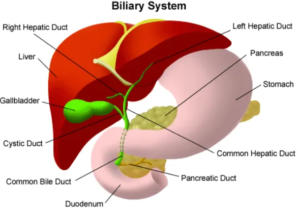
2.1 The Biliary system. The figure shows the liver location in the abdominal cavity.
7
2.2 The Anatomy of the Kidney 11
2.3 The Front View of Urinary Tract. The figure shows the kidneys’ location in the abdominal cavity.
12
2.4 The Anatomy of the Pancreas 19
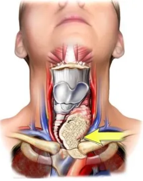
2.5 The anatomy of thyroid. The figure shows the thyroid location. 24
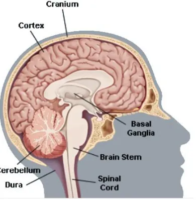
2.6 The brain is composed of three parts, the cortex the brain stem the basal ganglia the cerebellum
30
2.7 The brain is divided into several lobes, the frontal, the parietal, the temporal and occipital
30
3.1 A cross-section of an ultrasonic transducer 37
3.2 A diagram of a spherical HIFU Transducer with focal length of 100mm. 39
3.3 A photo of a typical HIFU Transducer. 39
3.4 How the ablation causes necrosis of tissue at the targeted area. 40
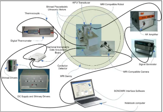
5.1 Block diagram of high intensity focused ultrasound (HIFU) system with the MRI guidance. This diagram shows the arrangement of the devices used in the HIFU system
66
5.2 Setup of the actual devices used for the HIFU system with the MRI guidance (The positioning device shown is the third version)
67
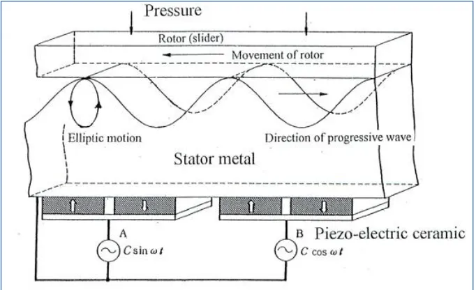
5.3 Diagram of the mechanism of the ultrasonic motor 69
5.4 Traveling Wave Formation 69
5.5 Inside structure of USM (USR60-S4) 70
5.6 A photo of piezoelectric ultrasonic motor by Shinsen USR60E3N 70
5.7 A photo of dedicated driver for Shinsei USR60 series, Shinsei D6060E. 71
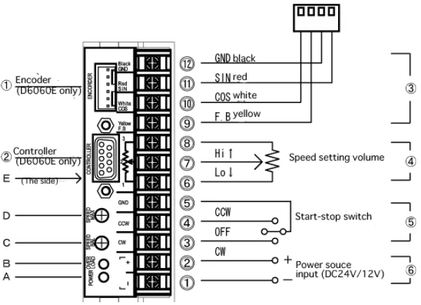
5.8 Basic connection diagram of the dedicated driver for Shinsei USR60 series, Shinsei D6060E
71
5.9 Wiring diagram of the motor drivers for 3 degrees of freedom positioning device.
72
5.10 The photograph shows the cavitation detector. 74
5.11 The photograph shows the MRI compatible camera 75
6.1 Corner part used to support the rods and the pulleys. This part is also used to support the different stages of the robot.
80
6.2 The brass rod used to support and guide the surface plates of the stages X, Y and Z.
81
6.3 Position of the brass screw which is used to mount the rod on the angular part.
81
6.4 The brass screws used to mount the parts of the positioning device. 81
6.5 Brass rod mounted on two angular parts which are attached on the base of the positioning device.
82
6.6 Diagrams and photos of surface plates of the base, X-Stage and Y-Stage.
83
6.7 Pulleys, timing belt, and the piezoelectric ultrasonic motor attached on the base with an angular part which is driving the timing belt to achieve the motion of a surface plate of the X-axis.
84
6.8 The pulleys on the other end of the timing belt hold with two angular parts.
84
6.9 Top view of the base with the brass rods that support and guide the X-axis plate. The timing belt is mounted on the X-X-axis plate (not shown here) with a brass screw.
85
6.10 The angular parts attached at the bottom of the X-axis plate are sliding along the brass rod which acts as a support and guide.
6.11 Drawings of the various mechanical stages of the positioning device. 87
6.12 Schematic of the robot showing all of its stages. 88
6.13 Photograph of the complete positioning device. 88
6.14 Coupling methods, A. In vitro or in vivo (tissue outside the water container). B. In vitro (tissue inside the water container).
89
7.1 CAD design and photograph of the base of the positioning device: A. CAD drawing, B. actual photo (with zooming in the guide).
93
7.2 A. CAD design of the X-axis plate and B. photograph of the X-axis plate base of the positioning device.
94
7.3 A photograph of the groove and the guide used for the motion of all axis plates.
94
7.4 A. CAD drawing of the X-axis plate mounted on the base and B. photograph of the X-axis plate mounted on the base.
95
7.5 A. the CAD drawing of the Y-axis plate of the positioning device and B. a photograph of the Y-axis plate of the positioning device.
95
7.6 A. the 3D drawing of the base and the X and Y-axis plates assembled together and B. the corresponding photograph of the base, X and Y-axis plates. The piezoelectric ultrasonic motor shown between the X and Y plates drives the Y-axis plate.
96
7.7 A. the 3D drawing of the holder of the Z-axis plate, the Z-axis plate with the PUM motor which moves the Z-axis plate and B. a photograph of the actual part of 7.7.A as developed and assembled.
96
7.8 A. the CAD drawing of the HIFU transducer holder attached on the Z-axis plate and B. a photograph of the HIFU transducer holder attached on the Z-axis plate.
97
7.9 A. the CAD drawing of the top plate of the positioning device and B. a photograph of the top plate of the positioning device. The piezoelectric motor shown moves the X-axis plate.
97
7.10 A. the final 3D drawing and B. the developed positioning device. 98
7.11 A photograph of the positioning device inside the gantry of the MRI scanner with a phantom gel target inside the tank which is filled with degassed water.
98
7.12 A. the base of the positioning device can be easily modified and B. the device as attached on the top of the gantry of the MRI scanner.
89
8.1 A. the CAD design of the base of the positioning device with the PUM motor attached to it and B. a photograph of the produced base of the positioning device with zooming in the groove in which the X-axis plate will slide in. The brass pinion attached to the PUM motor will drive the X-axis plate (back – forward motion).
104
8.2 A. the CAD design of the X-axis plate responsible for the back and forward motion and B. a photograph of the formed X-axis plate with zooming on the male guide which will slide in the corresponding groove of the base. The brass pinion shown here, will drive the Y-axis plate.
104
8.3 A. the CAD drawing of the base with the X-axis plate attached and B. a photograph of the base together with the X-axis plate. The X-axis plate will slide back and forward within the groove of the base. The piezoelectric ultrasonic motor shown here on the top of the X-axis plate is the motor that drives the Y-axis plate.
105
8.4 A. the CAD design of the axis plate and B. a photograph of the ABS Y-axis plate.
106
8.5 A. the 3D drawing of the base and the X and Y-axis plates assembled together and B. the corresponding photograph of the ABS base, X and Y-axis plates.
106
8.6 A. the 3D drawing of the holder of the Z-axis plate with the PUM motor which moves the Z-axis plate and B. a photograph of corresponding ABS axis holder and the PUM motor with the brass pinion that drives the Z-axis plate.
106
8.7 A. the CAD drawing of the Z holder attached on the support holder of the Y-axis plate and B. a photograph of corresponding ABS Z-axis holder attached on the Y-axis plate.
8.8 A. the CAD extension of the base that hosts the coupling and B. a photograph of the produced ABS extension of the base.
108
8.9 A. the CAD drawing of the base extension attached on the base of the robot and B. a photograph of the ABS base extension joined with the base of the robot.
108
8.10 A. the CAD drawing of the Z-axis plate and B. a photograph of the ABS Z-axis plate.
108
8.11 A. the CAD drawing of the Z-axis plate attached on the Z holder and B. the corresponding photograph of the ABS Z-axis plate positioned on the Z holder.
109
8.12 A. the CAD drawing of the water tank holder used for the coupling of the HIFU transducer with the targeted tumour and B. the corresponding photograph of the ABS water tank holder.
109
8.13 A. the CAD drawing of the degassed water container and B. a photograph of the acrylic glass container covered with milar bag.
110
8.14 A. the CAD drawing of the water tank holder fitted on the base extension and the water container placed inside the water tank holder and B. a photograph of the ABS water tank holder mounted on the ABS base extension and the acrylic glass container fitted inside the water tank holder.
110
8.15 A. the CAD drawing of the vertical HIFU transducer holder and B. the photograph of the corresponding ABS vertical HIFU transducer holder.
111
8.16 A. the CAD drawing of the horizontal HIFU transducer holder and B. the photograph of the corresponding ABS horizontal HIFU transducer holder.
111
8.17 A. the CAD drawing of the complete positioning device with the vertical HIFU transducer holder attached in the slot of the Z-axis plate and B. the photograph of the ABS vertical HIFU transducer holder mounted in the slot of the Z-axis plate.
112
8.18 A. the CAD drawing of the complete positioning device with the horizontal HIFU transducer holder attached in the slot of the Z-axis plate and B. the photograph of the ABS horizontal HIFU transducer holder mounted in the slot of the Z-axis plate.
112
8.19 A photograph showing how the robot can be used for brain tumours. 112
8.20 The CAD drawing of the robot inside the gantry of a typical MRI scanner. 113
8.21 A. a photograph of the robot with the MRI compatible camera outside the gantry of an MRI and B a photograph of the robot inside the gantry of an MRI scanner with the HIFU transducer immerse in the degassed water saline.
113
8.22 Photographs A and B show the robot placed in the gantry of an MRI scanner and are taken from the MRI compatible camera which is also placed in the gantry of the MRI scanner.
114
9.1 Photograph of the power supply and the three dedicated drivers (X, Y and Z)
118
9.2 Photograph of the rear panel of the enclosure that holds the dedicated drivers.
119
9.3 Photograph of the three dedicated drivers of the PUM motors mounted inside the enclosure
119
9.4 Photograph of the data acquisition board. National Instruments 6251 120
9.5 Photograph of the setup of the MR compatible camera 121
9.6 The thermocouple is connected directly to the analogue input of the data acquisition card.
121
9.7 The thermocouple is connected as shown in the diagram to the analogue input of the data acquisition card.
122
9.8 Omega thermocouple-to-analogue connector. 122
9.9 Data acquisition set up 123
9.10 The end-user interface used to capture the temperature fluctuations at the focal point of the HIFU transducer at specified time intervals.
123
9.11 Part of the temperature file stored during an experiment. 124
10.1 The photograph shows the ultrasound power meter, a device used to measure the ultrasound power of the transducers.
128
10.2 A. an MRI image of phantom without the presence of the motor. B. an MRI image of phantom with the presence of the motor. C an MRI image of the subtraction of the two images showing no shift.
132
10.3 Lesions created in pig kidney demonstrating the excellent repeatability of the positioning device.
132
10.4 Large lesion in pig kidney in vitro by moving the transducer in grid formation (8 X 8) (top view)
133
10.5 A Axial MR images of HIFU ablation using T2-weighted FSE (TE=32ms) pulse sequence. B Photograph after slicing.
133
10.6 MR images showing the focal beam during a 3 X 3 scanning using low intensity ultrasound using T1 weighted FSPGR.
134
10.7 MR images (in plane perpendicular to the transducer beam) of large lesions (full coverage of the intended target) using T2-Weighted FSE with TE = 32ms. The spatial average intensity was 1,500 W/cm2 for 5s
135
10.8 MR images (in plane perpendicular to the transducer beam) of large lesions (partial coverage of the intended target) using T2-Weighted FSE with TE = 32ms. The spatial average intensity was 2,000 W/cm2 for 5s
136
10.9 Photograph of the positioning device version 2 in the gantry of the MRI scanner. The gel phantom is immersed in the degassed water saline.
138
10.10 The MRI image shows the HIFU transducer, the phantom gel and the tank filled with degassed water saline using T2 W FSE.
139
10.11 The MRI image shows the HIFU transducer, the phantom gel and the tank filled with degassed water saline using FSPGR. The red arrow indicates the focal spot A. at position 1 B. at position 2 and C at position 3.
139
10.12 A Photograph of the positioning device version 3 on the table of the MRI scanner, B the positioning device version 3 in the gantry of the MRI scanner.
141
10.13 A the MRI image shows the HIFU transducer, and the phantom gel this image was captured using T1 W FSE, B the MRI image shows the phantom gel and the tube passes through the gel. The image was also captured using T1 W FSE.
141
10.14 The MRI image shows the phantom gel mounted within the plastic holders. The image captured using FSPGR in a plane inside the gel.
142
10.15 Photograph shows the positioning device version 3 with the porcine muscle placed under the tank filled with degassed water saline.
143
10.16 Exposure A, the cross section – depth 144
10.17 Exposure B, A is the top view of the lesion, B cross section showing the depth of the lesion.
144
10.18 A photograph of the positioning device on the table of the MRI with the tank filled with degassed water saline and the gel phantom at the bottom of the tank, B photograph of the positioning device inside the gantry of the MRI scanner.
145
10.19 An MRI image showing the coupling between the milar bag which is filled with degassed water saline and the gel phantom.
145
10.20 Photograph of the experiment setup showing the positioning device version 3 and the MRI compatible camera.
146
10.21 Photograph of the positioning device version 3 inside the gantry of the MRI scanner, taken from the MRI compatible camera.
147
10.22 Photograph of the MRI Gel inside the gantry of the MRI scanner taken from the MRI compatible camera
147
10.23 A MRI image with T1 FSE with the MRI camera in the gantry of the MRI scanner, B MRI image with T1 FSE without the MRI compatible camera.
148
11.1 A. show a photograph of large lesion created in the phantom at a plane perpendicular to the transducer beam axis. B. shows the corresponding photograph in a parallel plane. C. shows the MRI image of the result of A using T2–W FSE (for MRI parameters see Table 10.1, row 2), and D. shows the same result using T1-W FSE.
11.2 MRI guided HIFU system with cavitation detection system using the actual photos of the instruments.
151
11.3 POC as a function of in situ spatial average intensity for 5s pulse duration in liver.
154
11.4 A CNR between lesion and liver plotted against TR using T1-weighted FSE, B CNR between lesion and liver plotted against TE using T2-weighted FSE, C CNR between lesion and liver plotted against TR using T1-weighted FSPGR.
155
11.5 A MR images (in a plane perpendicular to the transducer beam) of large lesion using T2-weighte FSE showing cavitational lesions, B cavitational map of the above large lesion, C typical frequency spectrum acquired during the occurrence of a cavitational lesion.
156-157
11.6 MR images (in a plane parallel to the transducer beam) of large lesion using A T2-weigted FSE with TE=15ms. B Photograph after slicing.
157
11.7 Large lesion in liver in vivo using T1-w FSE 166
11.8 Photograph of the lesion shown in Figure 10.30 166
11.9 CNR vs TR 167
11.10 MRI image of the lesion of Figure 10.30 using T1W FSE 167
11.11 MRI images of the same lesion as in Figure 10.30 using T2W FSE. 168
11.12 CNR vs TE for the MRI image shown in 10.35 168
11.13 MR images (in a plane perpendicular to the beam) of four lesions (intensities 1000, 1500, 2000 and 2500 W/cm2) in kidney in vitro using A. T1-weighted FSE, B. T2-weighted FSE, C. T1-weighted FSPGR. With intensities above 2000 W/cm2 the lesions exhibit boiling activity. The discrimination between boiling and non-boiling lesion is best monitored using T2-W FSE.
176
11.14 MR images (in a plane parallel to the beam) of 3 lesions in kidney in vitro
using a) T1-weighted FSE, b) T2-weighted FSE, c). T1-weighted FSPGR. With intensities above 2000 W/cm2 the lesions exhibit boiling activity. The discrimination between boiling and thermal lesion is best monitored using T2-W FSE.
177
11.15 CNR vs. TE for the lesion, kidney and cavity for the lesion of Fig. 8B with intensity of 3000 W/cm2
178
11.16 MRI image using T2-weighted FSE of 3 lesions in rabbit kidney in vivo at different intensities (1000, 2000, and 2500 W/cm2) for a 5 s pulse. The lesion with intensity of 2500 W/cm2 is affected by tissue boiling
178
11.17 A. MR image (in a plane perpendicular to the beam) of large lesion in kidney in vitro using T1-weighted FSPGR (TR=50 ms), showing one cavitation lesion. B. Photograph of the kidney showing the cavitation lesion within the large thermal lesion, C. Frequency spectrum of the HIFU transducer exhibiting cavitation activity
179
11.18 Temperature evolution in vitro kidney using T1-weighted FSPGR (thermal mechanism). Each image was acquired in 5 s. a) Ultrasound is OFF b-f) applied spatial average intensity: 1000 W/cm2 (for 25 s), g-h) ultrasound is OFF
180
11.19 Temperature elevation in vitro kidney using T1-weighted FSPGR (boiling). a) Ultrasound is OFF b-f) applied spatial average intensity: 3500 W/cm2 (for 25 s)
181
11.20 MR image using proton density of lesion in liver created under the influence of boiling. The lesion was created using low intensity (1000 W/cm2) for long time (30 s)
List of tables
Table Page
3.1 The main historical events in the development of medical ultrasonic
49
3.2 Active companies in image guided ultrasound robotic systems 50-51
5.1 Design criteria and requirements for the development of the HIFU-MRI system.
64-65
9.1 The table above describes all the elements of the user interface of figure 9.12
125-126
11.1 Parameters used for the various MRI pulse sequences. 160
11.2 Parameters used for the various MRI pulse sequences 177
11.3 Recommended pulse sequences for discriminating between a) normal and thermal lesions and b) normal tissue, lesions created with temperature below boiling and lesions created with
temperature above boiling
183
13.1 Incidence rates by race of cancer of the liver and intrahepatic bile duct.
198
13.2 Death rates by race of cancer for the liver and intrahepatic bile duct.
199
13.3 Incidence rates by race of cancer for the kidney and renal pelvis in 2009
200
13.4 Death rates by race of cancer for kidney and renal pelvis in 2009. 200
13.5 Incident rates by race of pancreatic cancer 2009. 201
13.6 Death rates by race of pancreatic cancer 2009. 201
13.7 Incident rates by race of thyroid cancer 2009 202
13.8 Death rates by race of thyroid cancer 2009 203
13.9 Incident rates by race of brain and nervous system 2009 204
13.10 Estimated incidence, mortality and 5-year prevalence: Liver Cancer.
206
13.11 Estimated incidence, mortality and 5-year prevalence: Pancreatic Cancer.
206
13.12 Estimated incidence, mortality and 5-year prevalence: Kidney Cancer
206
13.13 Estimated incidence, mortality and 5-year prevalence: Thyroid Cancer.
207
13.14 Estimated incidence, mortality and 5-year prevalence: Brain and nervous system Cancer.
207
Acknowledgements
Sincere thanks to my principal supervisor Dr P. Kyriacou for his on-going support and guidance. I truly and appreciate his patience and understanding.
I am more than grateful and I truly appreciate the support and help from my external supervisor Dr C. Damianou, who gave me the idea of this research and guidance and support throughout the completion of this report.
Many thanks to my friends and colleagues Mr V. Hatdisavvas, Mr A. Kouppis for their help and support and they were always there ready to help me without any price.
DECLARATION FORM
THESIS DEPOSIT AGREEMENT
COVERED WORK
I Nicos Mylonas-Ariou Pagou 11, 4042, Yermasoyia, Lemesos, Cyprus ,“the Depositor”, would like to deposit “Development of positioning devices for MRI-guided high intensity focused ultrasound (HIFU) for abdominal, thyroid and brain, tumours”, hereafter referred to as the “Work”,in the City University Institutional Repository and agree to the following:
NON-EXCLUSIVE RIGHTS
Rights granted to the City University Institutional Repository through this agreement are entirely non-exclusive and royalty free. I am free to publish the Work in its present version or future versions elsewhere. I agree that the City University Institutional Repository administrators or any third party with whom the City University Institutional Repository has an agreement to do so may, without changing content, translate the Work to any medium or format for the purpose of future preservation and accessibility.
DEPOSIT IN THE CITY UNIVERSITY INSTITUTIONAL REPOSITORY
I understand that work deposited in the City University Institutional Repository will be accessible to a wide variety of people and institutions - including automated agents - via the World Wide Web. I also agree to an electronic copy of my thesis being included in the British Library Electronic Theses On-line System (EThOS).
I understand that once the Work is deposited, a citation to the Work will always remain visible. Removal of the Work can be made after discussion with the City University Institutional Repository, who shall make best efforts to ensure removal of the Work from any third party with whom the City University Institutional Repository has an agreement.
I AGREE AS FOLLOWS:
- That I am the author or co-author of the work and have the authority on behalf of the author or authors to make this agreement and to hereby give the City University Institutional Repository administrators the right to make available the Work in the way described above.
- That I have exercised reasonable care to ensure that the Work is original, and does not to the best of my knowledge break any UK law or infringe any third party’s copyright or other Intellectual Property Right. Where I have included third party copyright material, I have fully acknowledged its source.
- The administrators of the City University Institutional Repository do not hold any obligation to take legal action on behalf of the Depositor, or other rights holders, in the event of breach of intellectual property rights, or any other right, in the material deposited.
Abstract
This research focuses on the design and the development of three positioning
devices with the ability to accurately move a High Intensity Focused Ultrasound
(HIFU) transducer guided by a Magnetic Resonance Imaging (MRI) scanner in
order to create discrete and overlapping lesions in biological tissue such as a
brain, thyroid, kidney, liver and pancreas.
The positioning devices were designed and fabricated using construction
materials selected for compatibility with high magnetic fields and fast switching
magnetic field gradients encountered inside MRI scanners. The positioning
devices incorporate only MRI compatible materials such as piezoelectric
ultrasonic motors, plastic sheets, brass screws, plastic pulleys, brass racks and
pinions and timing belts.
The MRI compatibility of the system was successfully demonstrated in a clinical
high field MRI scanner. The robots have the ability to accurately move the
transducer thus creating discrete and overlapping lesions in biological tissue
and this was also tested successfully.
The main goals during the design and implementation of all three positioning
devices were similar and these were to implement a positioning device which is
simple, cost effective, portable, and can be used in virtually any clinical MRI
scanner either sited on the scanner's table or mounted on the top of the gantry
of the MRI.
Additionally the developed positioning devices incorporate a flexible coupling
system and thus they can be used in all the anatomies accessible by HIFU like
liver, kidney, breast, brain, pancreas and thyroids of for experiments in small
and large animals.
The three different positioning devices were developed either as an
improvement of one another, as in case of the first and third positioning devices,
or to be used for different application, as in case of the second and third
versions of positioning devices.
a. The first positioning device can be used for brain tumours.
b. The second version can be applied for experiments on large animals like
pig, sheep and dog and small animals like rabbit and rat. However, with a
slight modification of the base of this positioning device and with the
collaboration an MRI vendor can be attached on the top of the gantry of the
MRI scanner. Therefore, more space will be left for the target body and as a
result this positioning device will be suitable for abdominal tumours (kidney,
liver, and pancreas), brain and thyroid.
c. The third device which is an upgrade of the first positioning device can be
also used for treating brain tumours and additionally under certain conditions
it would be suitable for treating abdominal tumours, and thyroid.
The positioning devices were evaluated for their MRI compatibility, reliability,
accuracy and functionality, with several experiments on phantom gel, pork
kidney, porcine muscle and rabbit liver.
Furthermore, other experiments were conducted to evaluate the effects of the
HIFU / MRI system. The effectiveness of MRI to monitor therapeutic protocols
of HIFU in freshly excised pig liver and in rabbit liver in vivo were investigated.
The detection of large lesions using MRI was evaluated as well as the
possibility to create both thermal and cavitational lesions. MRI sequences were
best contrast between liver and lesion is obtained were also studied. The range
of repetition time (TR) and range of echo time (TE) which maximizes the
contrast to noise ratio (CNR) were investigated. Additionally, MRI was utilized to
monitor lesions created at temperature below the boiling point and lesions
created at temperature above the boiling point using HIFU in freshly excised
kidney, liver and in vivo rabbit kidney.
Results from 1942 since today have proved that HIFU is a very promising
technology and recent studies convince many experts that HIFU is the future in
medicine. Furthermore MRI guidance of a positioning device that guides HIFU
transducer for non-invasive interventions offers accuracy and reliability and it
appears to be very encouraging approach for treating tumours. The evaluation
of the proposed positioning devices is very optimistic for MRI guided HIFU
Abbreviations and symbols used
Abbreviation Expansion
1 ABS Acrylonitrile Butadiene Styrene
2 A/D Analogue to Digital
3 AI Analogue Input
4 AO Analogue Output
5 ALARA As Low As Reasonably Achievable
6 AVR Aortic Valve Replacement
7 BPH Benign Prostatic Hyperplasia
8 BW Bandwidth- a measure of frequency range, the
range between the highest and lowest frequency allowed
9 CAD Computer-Aided Design
10 CE Conformité Européene, meaning "European
Conformity
11 CAM Computer-Aided Manufacturing
12 CEA Carcinoembryonic Antigen
13 CNR Contrast to Noise Ratio
14 CPU Central Processing Unit
15 CT or CAT Computed Tomography scan
16 DIO digital input/output
17 DoF Degrees of Freedom
18 ETL Echo Train Length
19 ERCP Endoscopic retrograde cholangiopancreatography
20 FDA Food and Drug Administration
21 FOV Field of View
22 FSE Fast Spin Echo
23 FSPGR Fast Fpoiled Gradient echo
24 GI Gastrointestinal
25 HCC Hepatocellular carcinoma
26 HIFU High Intensity Focused Ultrasound
27 ICU Intensive Care Unit
28 IV Injection into a vein
29 IVP intravenous pyelogram
30 LTA Laser thermal ablation
31 MI Mechanic index
32 MRgHIFU Magnetic Resonance Image guided HIFU
33 MRI Magnetic Resonance Imaging
34 MRgFUS Magnetic Resonance Guided Focused Ultrasound
35 MTC Medullary thyroid carcinoma
36 NCI National Cancer Institute
37 NDT Non-Destructive Testing
38 NEX Number of Excitations
39 PET Positron Emission Tomography
40 PMI Profound Medical Inc.
41 PMMA Polymethyl methacrylate
43 PFI Programmable Function Interface
44 PSA Prostate-Specific Antigen
45 PTC Percutaneous Transhepatic Cholangiography
46 PUM Piezoelectric ultrasonic motors
47 RCC Renal Cell Carcinoma
48 ROI Region of Interest
49 SEER Surveillance, Epidemiology and End Results
50 SPECT Single Photon Emission Computed Tomography
51 SPTA Spatial Peak Temporal Average
52 TI Thermal index
53 TIB Bone Thermal Index
54 TIS Tissue Thermal Index
55 T1 The longitudinal relaxation time
56 T2 The transverse relaxation time
57 TE Time to Echo
58 TR Repetition Time
59 USP United States Plastic Company
1 Introduction
High intensity focused ultrasound (HIFU) is a promising technology for a variety
of therapeutic applications. This concept initiated in 1942 by Lynn Zwemer [1].
HIFU has long been known as a minimal invasive or non-invasive procedure
that destroys tissue through ablation. However, it is only in recent years that
clinical applications are becoming feasible, with the development of high power
ultrasound transducers compatible with the MRI scanner which is used to
monitor these non-invasive HIFU applications. New technologies, combined
with more sophisticated treatment methods and monitoring methods allow
non-invasive procedures in many areas such as the brain, eye, breast, kidney, liver,
pancreas, thyroid, uterine fibroids and pancreas. Meanwhile, new
investigations are underway for treading cardiac arithmia, strokes, palliative pain treatment of bone metastases and brain disorders such as Parkinson’s
disease, essential tremor, and neuropathic pain. These optimistic investigations
have encouraged physicians and provided them new valuable tools for medical
research.
After the introduction of the concept of HIFU in 1942 by Lynn Zwemer the first
complete system for the use of HIFU was developed by Fry Mosberg [2] in
1954. However, at that time Magnetic Resonance Imaging (MRI) did not exist and therefore the previous systems were not guided effectively, and therefore had
not survived in the clinical setting.
Jolesz and Jakab [3] in 1991 demonstrated that the MRI scanner can be used
to guide the HIFU transducer and about a year later Hynynen et al. [4], [5]
produce necrosis in a canine muscle using a HIFU transducer and monitored by
an MRI. After these first studies of producing lesions on tissues using a HIFU
transducer guided by an MRI, this concept was carried on in the following years
[6], [7] and they have proven that the contrast between necrotic tissue and
normal tissue was clearly observable. Therefore, MRI became the only
modality of guiding HIFU to create lesions.
Through the years it has been proven that HIFU can be used to accurately heat
the targeted biological tissues and therefore proven suitable for applications for
guided either by ultrasound or by MRI to provide, to the operator performing the
procedure, images of a region within the subject being heated [2].
Furthermore, HIFU was explored in almost every tissue that is accessible by
ultrasound. The propagation of HIFU can successfully generate discrete and
large lesions with reproducible results. The following literature represents some
examples of some applications explored: prostate [8], liver [9], brain [2],
[10]-[11], eye [12], kidney [13]-[14], pancreas [15], [16], breast [17] and thyroid
[18]-[22].
In the recent commercial systems (for example, [8], [23] and [24]) HIFU is either
guided by ultrasound or MRI. Although, ultrasonic imaging is the simplest and
most inexpensive method to guide HIFU, it is not as good as MRI as MRI offers
superior contrast than ultrasound. Also, the thermometry capability provided by
the MRI is unique and is used for the localization and the effect of the HIFU
beam at any time. However, the disadvantages of MRI are mainly its cost and
the fact that MRI imaging is not real time and this makes it difficult to point an
organ which is moving due to breathing.
Several examples of MRI compatible positioning devices (robot) have been
developed for other applications. Systems have been developed to perform
breast interventions [25]-[28], to perform brain biopsies [29], to perform prostate
procedures [30], [32], and one to perform general purpose procedures with the “doubledonut” scanner [33]. Although these studies have demonstrated the
technical feasibility of MR compatible manipulators, these devices are highly
specialized for a certain anatomy or MR scanner design.
The proposed positioning devices are prototypes magnetic resonance imaging
(MRI) compatible positioning devices used to move an MRI-guided high
intensity focused ultrasound (HIFU) transducer for the treatment of tumours by
producing lesions on the targeted areas. The future application of these
systems is to treat brain tumours (positioning devices versions 1 and 3)
abdominal tumours (liver, kidney and pancreas with versions 2 and 3) and
thyroid tumours (positioning devices version 2 and 3). Also, the positioning
devices can be used to perform experiments in large animals like pig, sheep
1.1
Aims and objectives
The aims and objectives of the thesis are listed below:
i. Design and implement a positioning device which will guide the HIFU
transducer to effectively destroy the targeted tumour and avoiding
lesions to healthy tissues
ii. The positioning device must be MRI compatible since it will be used
inside the gantry of an MRI scanner
iii. The positioning device must be small in size and light in weight and
therefore, portable
iv. Design and develop a universal positioning device which will be capable
to operate in the gantry any MRI scanner.
v. The positioning device should be flexible and should be easily modified
for many different applications
vi. Design and develop a user friendly interface software application to be
used to guide the positioning. Furthermore, the software application will
provide the user with several other functions like,
digital thermometer to capture the temperature variations at the HIFU transducer focal point,
store patient treatment history,
set the ultrasound treatment protocol, settings of the HIFU treatment, i.e. the parameters of the given therapy like intensity,
frequency, starting and ending times,
maintain patient database with data of the patients treated which can be used for statistical purposes,
display of MRI images The MRI images of each treatment will be stored and the user has the ability to load any image stored,
display video or pictures captured from the MR compatible camera An MRI compatible camera is connected on the system. The
camera was interfaced by means of a video capture card. With
the aid of the MRI compatible camera, the researcher can monitor
1.2
Chapters Outline
This section gives an overview of each chapter in this report.
Chapter 2: Abdominal and thyroid tumours
Kidney, liver and pancreatic tumours are the abdominal tumours
considered in this report. Thyroid tumours are also considered
and therefore this chapter covers the most common tumours of
these organs as well as the symptoms, diagnostic methods and
treatments used. Treating these tumours using HIFU is not
explained in this chapter since this method is described in details
in chapter 3.
Chapter 3: High Intensity Focused Ultrasound (HIFU) technology and therapeutic applications
This chapter gives an overview of the physics and technology of
HIFU and HIFU transducers. Also, describes how HIFU can be
used for treating tumours and how Magnetic Resonance Imaging
(MRI) can be utilized for the guidance of HIFU transducers.
Furthermore, MRI compatibility and safety issues as well as
therapeutic HIFU applications and historical events of therapeutic
HIFU are also described.
Chapter 4: Applications of HIFU in medicine
The current state for treating abdominal and thyroid tumours
using HIFU technology experimentally and commercially is
described in this chapter.
Also, in this chapter HIFU technology for treating abdominal and
thyroid tumours is compared with the current treatment methods
for treating these tumours and advantages and limitations are
summarized. This chapter also gives an overview of MRI guided
HIFU (MRgHIFU) systems and MRI compatible positioning
devices and exhibits the existing MRgHIFU positioning devices.
Chapter 5: Development of HIFU system with MRI guidance
This chapter describes the parts and the setup of a HIFU system.
MRI compatible materials like piezoelectric motors, piezoelectric
ultrasonic transducer MRI compatible camera and cavitation
Chapter 6: Development of the positioning device version 1
The description, the application, the parts and materials used,
the designs, the development of the different components as well
as the integration of the first version of the proposed positioning
device are given in this chapter.
Chapter 7: Development of the positioning device version 2
This chapter gives an overview of the applications, the materials,
the designs of the different components used and the
development and integration of the second version of the
proposed MRI compatible positioning device.
Chapter 8: Development of the positioning device version 3
This third version of the proposed positioning device, as
mentioned earlier, is an advancement of the first version. In this
chapter the applications, the materials used, the design of the
different parts, the development and the integration of the third
positioning device are explained in details.
Chapter 9: Software development
This chapter explains the development of the software that will
be used to control the HIFU system. The digital thermometer,
transducer movement, treatment history, ultrasound treatment
protocol, and patient database, are the main functions of the
software and these are presented in this chapter.
Chapter 10: Evaluation of the MRI compatible positioning devices
This chapter describes how the MRI compatible devices are
tested and evaluated. All the experiments made to evaluate
HIFU ablation and the MRI compatibility of the HIFU system are
analysed.
Chapter 11: Conclusion and future enhancements
Conclusions and future enhancements are described in this last
2 Abdominal and thyroid tumours
This research primarily focuses on the design and development of three
positioning devices which will be used in an MRI to guide the HIFU transducer
to treat the brain, the thyroid and abdominal tumours. More specific, the
abdominal tumours are tumours appearing on organs such as the liver, kidney
and pancreas. These organs are the abdominal organs where HIFU has been
tested by previous researchers, liver [9], [34]-[47], kidney [13], [14], [34],
[46]-[49] and pancreas [15], [16]. Thyroid tumours were also studied and tested by
previous researchers [18]-[22]. Abdominal or thyroid tumour is an abnormal
growth of mass in the abdominal region of the body and this is a result of an
abnormal growth of the cells in this area. The positioning device will guide the
HIFU transducer to ablate the tumour area with and this process will be
monitored by an MRI scanner.
In this chapter the basic anatomy and physiology of these abdominal organs,
and the thyroid will be described. Also, in brief there will be description of the
tumours manifested in these organs together with a synopsis of the current
main treatment regimes.
2.1
Liver tumours
The liver is located in the upper right-hand portion of the abdominal cavity,
beneath the diaphragm, and on top of the stomach, right kidney, and intestines
[50]. The anatomy of the liver is shown in figure 2.1.
The liver regulates most chemical levels in the blood and excretes a product
called bile, which helps carry away waste products from the liver. All the blood
leaving the stomach and intestines passes through the liver. The liver
processes this blood and breaks down the nutrients and drugs into forms that
are easier to use for the rest of the body.
Important to note is that the liver can lose three-quarters of its cells before it
stops functioning. In addition, the liver is the only organ in the body that can
Figure 2.1: The Biliary system. The figure above shows the liver location in the abdominal cavity [50].
Liver tumours are divided to two categories, the non-cancerous and the
cancerous (malignant). In this section the different types of tumours are
discussed.
2.1.1 Non-cancerous liver tumours
The symptoms of these tumours usually are not noticeable and they are only
detected incidentally when an ultrasound scan, or computer tomography or CT
scan or Magnetic Resonance imaging (MRI) is performed on the patient.
Hepatocellular adenoma which appears usually in women at young age and the
hemangioma which is a mass of abnormal blood vessels. There are no
treatment for these, apart for some cases of infants with large liver
hemangiomas who might require surgery to prevent clotting and heart failure
[50]-[54].
2.1.2 Cancerous liver tumours
Cancerous (malignant) liver tumours are also subdivided to primary liver cancer
and secondary liver cancer. Primary liver cancer is one that starts in the liver
another part of the body (metastatic liver cancer). Most cancerous liver tumours
are secondary [53]-[59].
a.
Primary liver cancers
Hepatoma is a type of primary liver cancer and is also called hepatocellular
carcinoma. Hepatoma is the most common form of primary liver cancer. Some
of the causes of this primary liver cancer are chronic infection hepatitis B and C,
alcoholism and chronic liver cirrhosis.
b.
Diagnostic methods for liver hepatoma
Diagnosis of hepatoma is done through the medical history of the patient and a
physical examination.
The following are some diagnostic procedures for liver hepatoma [50]-[54]:
Liver function tests, a series of special blood tests that can determine if the liver is functioning properly.
Abdominal ultrasound (also called sonography), a diagnostic imaging technique which uses high-frequency sound waves to create an image of
the internal organs. Ultrasounds are used to view internal organs of the
abdomen such as the liver, spleen, and kidneys and to assess blood flow
through various vessels.
Computed Tomography scan (CT or CAT scan), a diagnostic imaging
procedure using a combination of x-rays and computer technology to
produce cross-sectional images (often called slices), both horizontally
and vertically, of the body. A CT scan shows detailed images of any part
of the body, including the bones, muscles, fat, and organs. CT scans are
more detailed than general x-rays.
Hepatic arteriography, x-rays taken after a substance in injected into the hepatic artery.
Liver biopsy, a procedure in which tissue samples from the liver are
removed (with a needle or during surgery) from the body for examination
c.
Treatment methods for liver hepatoma
For the treatment of liver hepatoma several approaches are used some of
which are listed below [50]-[54]:
Surgical resection can only be used in some cases to remove cancerous tissue from the liver. However, the tumour must be small and
confined.
Radiation therapy that uses high-energy rays to kill or shrink cancer cells.
Chemotherapy that uses anticancer drugs to kill cancer cells. Liver transplantation
Thermal ablation methods using HIFU are also used and these are
discussed in detail later in this report.
d.
Other Types of primary liver cancers
Other types of primary liver cancers which are less common are the following:
Cholangiocarcinoma, a cancer that originates in the lining of the bile channels in the liver or in the bile ducts.
Hepatoblastoma, a cancer in infants and children, sometimes causing
the release of hormones that result in early puberty.
Angiosarcoma, a rare cancer that originates in the blood vessels of the liver.
According to the National Cancer Institute primary liver cancer passes through
the following stages:
localized resectable. Cancer is in one place and can be removed completely with surgery.
localized unresectable. Cancer is in one place, but cannot be totally
removed.
Advanced. Cancer has spread through the liver and other parts of the body.
e.
Secondary Liver cancers (metastatic liver cancers)
As explained earlier in section 2.1.2 secondary liver cancer is one that has
spread from other areas in the body to the liver. These metastatic cancers
infecting the liver usually start from the lung, breast, colon, pancreas, and
stomach. Blood cancers including Leukemia are also spread to the liver
sometimes.
f.
Diagnostic methods for metastatic liver cancer
Diagnosis of metastatic liver cancer is done through the medical history of the
patient and a physical examination.
The diagnostic procedures used for metastatic liver cancer are very similar as
the one described above for liver hepaptoma.
g.
Treatment methods for metastatic liver
For the treatment of metastatic liver cancer several approaches are used some
of which are listed below:
Surgical resection as mentioned previously for primary liver cancers can only be used in some cases to remove cancerous tissue from the
liver. However, the tumour must be small and confined.
Radiation therapy which uses high-energy rays to kill or shrink cancer cells.
Chemotherapy that uses anticancer drugs to kill cancer cells.
Thermal ablation methods using HIFU are also used and these are discussed in detail later in this report.
Hepatocellular carcinoma (HCC), a primary liver cancer described above in
primary liver cancers section is considered to be one of the most common
malignancies worldwide, and metastatic liver cancers are the most common
2.1.3 Liver cancer statistics
The statistical information shown in appendix 12.3 was taken from the National
Cancer Institute (NCI) [51] and from the World Health Organization-International
Agency for research on Cancer [55].
2.2
Kidney tumours
Renal is the Latin word for kidneys and therefore the word renal is common
when referring to kidneys. The kidneys are two dark-red, bean-shaped organs
one on each side of the backbone, above the waist. There is a cavity attached
to the indented side of the kidney, called the renal pelvis which extends into the
ureter [50]-[54]. Each kidney is enclosed in a transparent membrane called the
renal capsule which helps to protect them against infections and
trauma. Nephrons are about one million of microscopic structures inside each
kidney responsible for filtering the blood removing waste products and making
urine. The urine passes from each kidney into the bladder through a long tube
called a ureter. The bladder stores the urine until it is passed from the body.
Blood is delivered to the kidneys through the renal artery and over 180 litres of
blood pass through the kidneys every day. When this blood enters the kidneys it
is filtered and returned to the heart via the renal vein. Figure 2.2 shows the
anatomy of the kidney.
[image:28.595.236.412.550.737.2]Kidneys are located towards the back of the abdominal cavity, just above the
waist. One kidney is normally located just below the liver, on the right side of
the abdomen and the other is just below the spleen on the left side. Figure 2.3 shows the kidneys’ location in the abdominal cavity.
The kidney is full of blood vessels since every function of the kidney involves
blood; therefore, it requires a lot of blood vessels to facilitate these functions.
Together, the two kidneys contain about 160 km of blood vessels.
Figure 2.3: The Front View of Urinary Tract. The figure above shows the kidneys’ location in the abdominal cavity [50].
The size of an adult human kidney is about 10 to 13 cm long and about 5 to 7.5
cm wide and weighs approximately 150 grams. Kidneys weigh about 0.5% of
total body weight.
Kidney cancers are also called renal cancers. Kidney cancers are also divided
to different types. These types of cancers, their symptoms and the method used
for the treatment of these tumours are explained below.
2.2.1 Non-cancerous kidney tumours
Benign kidney tumours are noncancerous. The symptoms of these tumours are
Renal adenomas are the most common form of benign, solid kidney tumour, and are typically small, low-grade growths. Their cause is unknown. Because
they usually are asymptomatic, their incidence is unknown, although one study
found them present in 7% to 22% of autopsy cadavers. In rare cases, when
they have grown large enough to affect kidney function or adjacent vessels,
symptoms similar to those of renal cell carcinoma (RCC) may occur.
Renal Oncocytoma is a benign, usually asymptomatic tumour that can grow quite large. They can develop throughout the body and are not unique to the
kidneys. Their cause is unknown, and they appear with greater frequency in
men than in women. Typically, they are discovered incidentally by ultrasound,
IVP, CT, or MRI scan for an unrelated health problem.
Under a microscope, many oncocytomas resemble early-stage RCCs. Many
physicians regard them as precancerous growths to be surgically removed
unless the patient's age or overall health condition dictates otherwise.
Angiomyolipoma also known as renal hamartoma, angiomyolipomas are rare benign tumours usually caused by an inherited genetic mutation. They can
occur on an isolated, individual basis, but most often are associated with a rare
genetic disease called tuberous sclerosis, which can cause tumours in the skin,
kidneys, brain, and other organ systems. About 80% of persons diagnosed with
tuberous sclerosis also have angiomyolipoma.
In patients without tuberous sclerosis, these tumours most often occur in
middle-aged women. Most cases are discovered when the patient undergoes a
CT scan for an unrelated abdominal problem, suffers gastrointestinal
discomfort, or suffers a sudden hemorrhage caused by the rupture of a large
tumour.
Management of the condition depends on the size of the tumours and the
severity of the symptoms they produce. Asymptomatic patients and those with
small tumours usually are not treated; instead, they are observed periodically
with an eye toward surgery if the tumours grow or produce symptoms. Because
of the potential for spontaneous rupture and life-threatening hemorrhage,
patients with large tumours usually are considered candidates for some form of
Fibromas are tumours of the fibrous tissue on, in, or surrounding the kidney. They are rare and are more common in women. Their cause is unknown and
most do not cause symptoms. Usually they grow on the periphery of the kidney
and can become large before becoming clinically obvious. While generally
benign, these tumours have no special characteristics to differentiate them from
malignant tumours of the kidney. Because of this uncertainty of diagnosis,
partial or radical nephrectomy is the standard treatment.
Lipomas are rare renal tumours that originate in the fat cells within the renal capsule or surrounding tissue. They typically occur in middle-aged women, can
grow very large, and produce pain and hematuria. Like many benign tumours,
they may become cancerous and usually are treated with total nephrectomy.
2.2.2 Cancerous kidney tumours
Several types of cancer can start in the kidney. When kidney cancer spreads
outside the kidney, cancer cells are often found in nearby lymph nodes. Kidney
cancer also may spread to the lungs, bones, liver or even from one kidney to
the other [51], [57]-[59].
a.
Types of cancerous kidney tumours
Kidney cancerous tumours include renal cell cancer, the most common type of
kidney cancer in adults and the transitional cell carcinoma which affect the renal
pelvis. Wilms tumour is another kidney cancer which is the most common type
of childhood kidney cancer. It also includes renal sarcoma a rare type of kidney cancer that starts in the kidney’s blood vessels. These kidney cancer types are
described below [51], [57]-[59].
Renal cell cancer (RCC) is the most common type of kidney cancer in adults and it is also called renal adenocarcinoma or hypernephroma. More than 8 in
every 10 kidney cancers diagnosed in the UK are RCC. In renal cell cancer the
cancerous cells start in the lining of very small tubes in the kidney that help filter
the blood and remove waste products through urine.
Clear cell renal cell carcinoma: This is the most common form of RCC. About 7 out of 10 people with RCC have this kind of cancer. When seen
under a microscope, the cells that make up clear cell RCC look very pale
or clear.
Papillary renal cell carcinoma: This is the second most common subtype – about 1 out of 10 people with RCC have this kind. These
cancers make little finger-like projections (called papillae) in some, if not
most, of the tumor. Some doctors call these cancers chromophilic
because the cells take up certain dyes used to prepare the tissue to be
looked at under the microscope. The dyes make them look pink.
Chromophobe renal cell carcinoma: This subtype accounts for a few cases of RCCs. The cells of these cancers are also pale, like the clear
cells, but are much larger and differ in other ways.
Collecting duct renal cell carcinoma: This subtype is very rare. The major feature is that the cancer cells can form irregular tubes.
Unclassified renal cell carcinoma: In rare cases, renal cell cancers are called as “unclassified” because they don’t fit into any of the other groups
or because more than one type of cell is present.
Transitional cell carcinoma are tumours that begin in the renal pelvis, the point where the kidney joins the tube that carries urine form the kidney to the
bladder (ureter), and not in the kidney itself. About 7 or 8 out of every 100 (7 to
8 %) kidney cancers diagnosed in the UK are transitional cell carcinomas, also
known as urothelial carcinomas.
The symptoms of transitional cell carcinoma are quite similar to those of RCC,
and include haematuria and back or flank pain.
At early stage these cancers have a 90% cure rate. Treatment usually involves
surgical removal of the kidney, ureter, and portion of the bladder connecting to
the ureter. Depending on the stage of the cancer, chemotherapy and radiation
may be used as adjuvant treatments.
Wilms' Tumour is a type of kidney cancer that usually develops in children under the age of 5. About 5% of all kidney cancers are Wilms tumours also
![Figure 2.2: The Anatomy of the Kidney [50]](https://thumb-us.123doks.com/thumbv2/123dok_us/1577448.110332/28.595.236.412.550.737/figure-anatomy-kidney.webp)

![Table 3.1: The main historical events in the development of medical ultrasonic are listed in the above table [90]](https://thumb-us.123doks.com/thumbv2/123dok_us/1577448.110332/66.595.115.540.388.714/table-historical-events-development-medical-ultrasonic-listed-table.webp)
![Table 3.2: malignant tumours Active companies in image guided ultrasound robotic systems [79], [86]](https://thumb-us.123doks.com/thumbv2/123dok_us/1577448.110332/68.595.107.541.55.587/table-malignant-tumours-active-companies-ultrasound-robotic-systems.webp)