WEB CRIPPLING BEHAVIOUR OF COLD-FORMED STEEL
CHANNEL SECTIONS WITH WEB HOLES SUBJECTED TO
INTERIOR-ONE-FLANGE LOADING CONDITION - PART II:
PARAMETRIC STUDY AND PROPOSED DESIGN EQUATIONS
Ying Liana, Asraf Uzzamanb, James B.P Lima,c, Gasser Abdelald, David Nashb, Ben Younge
a SPACE, David Keir Building, Queen’s University, Belfast, BT9 5AG, UK
b Department of Mechanical and Aerospace Engineering, The University of Strathclyde, 75 Montrose Street, Glasgow G1 1XJ, UK c Civil & Environmental Engineering, The University of Auckland, 20 Symonds Street, Auckland, New Zealand
d Department of Mechanical and Aerospace Engineering, Queen’s University, Belfast, BT9 5AH, UK e Department of Civil Engineering, The University of Hong Kong, Pokfulam Road, Hong Kong
Abstract
A parametric study of cold-formed steel sections with web openings subjected to web crippling under interior-one-flange (IOF) loading condition is undertaken, using finite element analysis, to investigate the effects of web holes and cross-sections sizes. The holes are located either centred beneath the bearing plate or with a horizontal clear distance to the near edge of the bearing plate. It was demonstrated that the main factors influencing the web crippling strength are the ratio of the hole depth to the depth of the web, the ratio of the length of bearing plate to the flat depth of the web and the location of the holes as defined by the distance of the hole from the edge of the bearing plate divided by the flat depth of the web. In this study, design recommendations in the form of web crippling strength reduction factor equations are proposed, which are conservative when compare with both the experimental and finite element results.
Keywords
Nomenclature
A Web holes ratio;
a Diameter of circular web holes;
bf Overall flange width of section;
bl Overall lip width of section; COV Coefficient of variation;
d Overall web depth of section;
dhole
ded
Clear distance between holes; Clear distance between holes;
DL Dead load;
E Young’s modulus of elasticity; FEA Finite element analysis;
Fm Mean value of fabrication factor;
fy Material yield strength;
h Depth of the flat portion of web;
L Length of the specimen;
LL Live load;
Mm Mean value of material factor;
N Length of the bearing plate;
P Experimental and finite element ultimate web crippling load per web;
PBS Nominal web crippling strength obtained from British Standard;
PEuro Nominal web crippling strength obtained from European Code;
PEXP Experimental ultimate web crippling load per web;
PNAS Nominal web crippling strength obtained from North American Specification;
Pm Mean value of tested-to-predicted load ratio;
R Reduction factor;
RP Proposed reduction factor;
ri Inside corner radius of section;
t Thickness of section;
VF Coefficient of variation of fabrication factor;
VM Coefficient of variation of material factor;
VP Coefficient of variation of tested-to-predicted load ratio;
x Horizontal clear distance of the web holes to the near edge of the bearing plate; X Web holes distance ratio;
θ
Angle between web and bearing surfaceβ Reliability index;
1 Introduction
Most design specifications for cold-formed steel structural members provide design rules for cold-formed steel channel sections without web holes; only in the case of the North American Specification for cold-formed steel sections [1] are reduction factors for web crippling with holes presented, covering the cases of interior-one-flange (IOF) and end-one-flange loading (EOF), and with the flanges of the sections unfastened to the support. This strength reduction factor equation, however, was limited to thicknesses ranging from 0.83 mm to 1.42 mm. In addition, in the North American Specifications, the holes are assumed to be located at the mid-height of the specimen having a longitudinal clear offset distance between the edge of the bearing plates and the web hole.
In the literature, for the IOF loading condition, Yu and Davis [2] previously considered the case of both circular and square web openings located and centred beneath the bearing plate with the flange unfastened to bearing plate. It should be noted that the test arrangement reported did not use the newly established IOF testing procedure [3] in which back-to-back channel-sections specimens were loaded, but instead used two channel -sections connected through their lips. Nevertheless, these tests remain the only reported tests in the literature for the IOF loading condition where the holes are located and centred beneath the bearing plate. For circular holes a total of 10 tests were reported, all tested with a bearing length of 89 mm. A strength reduction factor equation was proposed but was limited to the aforementioned bearing length.
considered rectangular web openings located and centred beneath the bearing plate under the interior-one-flange loading condition, and Zhou and Young [6] who proposed strength reduction factor equations for aluminium alloy square sections with circular web openings located and centred beneath the bearing plates under end-and interior-two flange loading conditions.
Strength reduction factor equations have recently been proposed by Uzzaman et al. [7-10] for web crippling strength of cold-formed steel channel -sections with circular holes in the web under the end-two-flange (ETF) and interior-two-flange (ITF) loading conditions. Recent research on web crippling of cold-formed steel channel-sections, other than that by Uzzaman et al., who again considered only the two-flange loading conditions, has not covered the case of holes [11-14].
2
Experiment investigation
Lian et al. [15] presented a test programme on cold-formed steel channel sections with circular web holes subjected to web crippling, as shown in Fig. 2. As can be seen, each test comprised a pair of channel sections with load transfer blocks bolted between them. Washer plates of thickness 6 mm were bolted to the outside of the webs of the channel -sections. The size of the web holes was varied in order to investigate the effect of the web holes on the web crippling strength. Circular holes with nominal diameters (a) ranging from 55 mm to 179 mm were considered in the experimental investigation. The ratio of the diameter of the holes to the depth of the flat portion of the webs (a/h) was 0.2, 0.4 and 0.6. All test specimens were fabricated with web holes located at the mid-depth of the webs andcentred beneath the bearing plate or with a horizontal clear distance to the near edge of the bearing plate (x), as shown in Fig. 1. The test data reported in the companion paper [15] are used in this paper for the development of web crippling strength reduction equations.
3 Numerical Investigation
specified in the ABAQUS manual [16]. Finite element mesh sizes were 5 mm × 5 mm for the cold-formed steel channel sections and 8 mm × 8 mm for the bearing plates and load transfer block.
The channel section specimens were tested in pairs, which were bolted to load transfer blocks at the end of specimens through the web by vertical row of M16 high tensile bolts. In the shell element idealisation, cartesian connectors with an in-plane stiffness were used to simulate bolt-hole elongation instead of physically modelling bolts and holes. “CONN3D2” connector elements were used to model the in-plane translational stiffness i.e. y- and z-directions. The in-plane stiffness of the connector element was 10 kN/mm, which Lim et al. [19] suggestion would be suitable. In the x-direction, the nodes were prevented from translating.
4 Parametric Study
The finite element model developed closely predicted the behaviour of the channel sections with circular web holes subjected to web crippling. Using these models, parametric studies were carried out to study the effects of web holes and cross-section sizes on the web crippling strengths of channel sections subjected to web crippling. The cases of both flange fastened and flange unfastened to the bearing plate were considered.
The specimens consisted of three different section sizes, having thicknesses (t) ranging from 1.2 mm to 6.0 mm and web slenderness (h/t) values ranging from 109 to 157.8. The ratios of the diameter of the holes (a) to the depth of the flat portion of the webs (h) were 0.2, 0.4, 0.6 and 0.8. The ratios of the distance of the holes (x) to the depth of the flat portion of the web (h) were 0.2, 0.4 and 0.6. Bearing plates of lengths (N) equal to 100 mm, 120 mm and 150 mm are considered. For each series of specimens, the web crippling strengths of the sections without the web holes were obtained. Thus, the ratio of the web crippling strengths for sections with web holes divided by the sections without web holes, which is the strength reduction factor (R), was used to quantify the degrading influence of the web holes on the web crippling strengths. The material properties obtained from the coupon tests as presented in the companion paper [15] were used in the finite element models in the parametric study. In Tables 1 to 6, the specimens were labelled such that the nominal dimension of the specimen and the length of the bearing as well as the ratio of the diameter of the holes to the depth of the flat portion of the webs (a/h) could be identified from the label. Details of the specimens labelling are described in the companion paper [15].
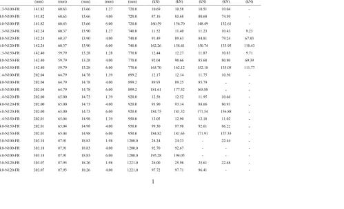
For the centred hole, a total of 193 specimens was analysed in the parametric study investigating the effect of the ratios of a/h and N/h.The cross-section dimensions as well as the web crippling strengths (PFEA) per web predicted from the FEA are summarised in Tables 1 and 2.
thinner. From Fig. 3(b), it can be seen that the reduction in strength is slightly less for the flange fastened case, compared with the flange unfastened case.
From Fig. 4(a), it can be seen that the reduction in strength is not sensitive to the ratio N/h. Again the 6 mm thick sections have the smallest reduction in strength (or the highest strength reduction factor); also, as the parameter a/h increases the reduction in strength decreases. From Fig 4(b), it can be seen that for the flange fastened case that there is almost no reduction in strength for a ratio of N/h of unity.
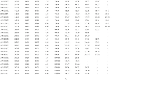
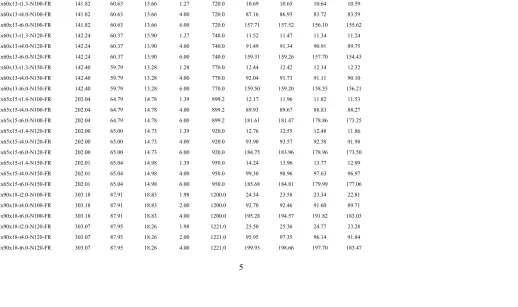
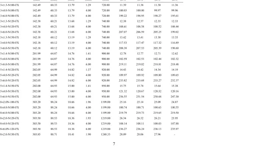
For the offset hole, a total of 512 specimens was analysed in the parametric study investigating the effect of a/h and x/h. The cross-section dimensions as well as the web crippling strengths (PFEA) per web predicted from the FEA are summarised in Tables 3 to 6.
The effect of the ratios a/h and x/h on the reduction factor of the web crippling strength is shown in Figs. 5 and 6 for the C142 specimen. From Fig. 5(a), as can be expected, as the parameter a/h increases that the reduction in strength also increases (or the strength reduction factor decreases); however, this reduction in strength is very small. From Fig. 5(b), it can be again be seen that the reduction in strength is slightly less for the flange fastened case, compared with the flange unfastened case.
From Fig. 6 (a) it can be seem that the reduction in strength is more sensitive to the ratio x/h. The reduction in strength can also be seen to be sensitive to the ratio of a/h. From Fig. 6(b), it can again be seen that the reduction in strength is slightly less for the flange fastened case, compared with the flange unfastened case.
5 Reliability analysis
recommended as a lower limit in the NAS [1]. The design rules are considered to be reliable if the reliability index is greater than or equal to 2.5. The load combination of 1.2DL + 1.6LL as specified in the American Society of Civil Engineers Standard [20] was used in the reliability analysis, where DL is the dead load and LL is the live load. The statistical parameters are obtained from Table F1 of the NAS [1] for compression members, where Mm = 1.10, Fm = 1.00, VM = 0.10, and VF = 0.05, which are the mean values and coefficients of variation for material properties and fabrication factors.
The statistical parameters Pm and VP are the mean value and coefficient of variation of load ratio are shown in Table 11 to Table 14 , respectively. In calculating the reliability index, the correction factor in the NAS Specification was used. Reliability analysis is detailed in the NAS [1]. In the reliability analysis, a constant resistance factor (
φ
) of 0.85 was used. It is shown that the reliability index (β) is greater than the target value of 2.5 as shown in Table 11 to Table 14.6 Comparison of the experiment and numerical results with current design
strengths for cold-formed steel sections without web holes
As mentioned earlier, the current cold-formed design standards [1,17,18, 20] do not provide design recommendations for cold-formed steel sections with web holes subjected to web crippling under IOF loading conditions, where the hole is located centred beneath the bearing plate. However, the web crippling strengths for sections without holes, from tests and FEA results, can be compared with the web crippling strengths obtained from design codes.
for the case of flange unfastened to the bearing plate, is limited to specimen thicknesses ranging from 1.194 mm to 1.326 mm and yield stress ranging from 301.8 MPa to 324.6 MPa. It should, however, be noted that the above range of specimens were considered for the results comparison.
For the case of flange unfastened to the bearing plate, Table 7 shows the comparison of web crippling strength with design strength for the IOF loading condition. The current design standard NAS design strength does not consider ri/t ratios greater than 3. In the British Standard [17] and Eurocode [18] comparison, the mean values of the ratios are 1.20 and 1.12 with the corresponding coefficients of variation (COV) of 0.063 and 0.103, respectively.
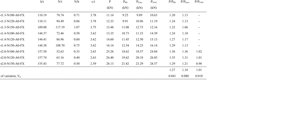
For the case of flange fastened to the bearing plate, Table 8 shows the comparison of web crippling strength with design strength for the IOF loading condition. The British Standard and Eurocodes provide unreliable web crippling strengths predictions for the case of flanges fastened. A comparison of these values with the corresponding experimental and numerical values indicates that although the British Standard and Eurocode values are lower bound, they are about 27% lower than the experimental and numerical failure loads. It is noted that British Standard and Eurocode are too conservative for the web crippling strengths of cold-formed steel lipped channel sections without web holes. The current design code NAS design strength does not consider ri/t ratios greater than 3.
7 Comparison of the experiment results with reduction factors (Yu and Davis) for
cold-formed steel section with web holes
test results were compared with the web crippling strength obtained from Yu and Davis [6].
In accordance with Yu and Davis [2], for centred holes for the case with the flange unfastened to the bearing plate,
) ( 6 . 0 0 . 1 h a
R= − (1)
where the limits for the reduction factor equation (1) are N = 89 mm, 66.7 ≤ h/t ≤101 and a/h ≤0.5.
Table 9 compares of the web crippling strength with that of Yu and Davis [2] for a centred hole for the case of flange unfastened to the bearing plate. As can be seen, the value of Pm is 1.35 with a corresponding COV of 0.072 i.e. the design strengths obtained from Yu and Davis are very conservative and are on average 35% lower than the experimental failure loads. However, as noted previously, the test arrangement of Yu and Davis did not use the now established IOF testing procedure, but instead used two channel -sections connected through their lips.
8 Comparison of the experiment and numerical results with current design
strengths (NAS) for cold-formed steel sections with web holes
As mentioned earlier, the current design standard NAS [1] provides design rules for web hole located at the mid-height of the specimen having a horizontal clear distance to the near edge of the bearing plate for the case of flange fastened to the bearing plate. The web crippling strength predicted from test and FEA results were compared with the web crippling strength obtained from the current design standard NAS [1].
In accordance with NAS [1], for offset holes for the case with the flange fastened to the bearing plate,
=0.9−0.047 +0.053 ≤1.0
h x h
a
where the limits for the reduction factor equation (2) are N ≥ 76 mm, h/t ≤200, ,
7 . 0 /h≤
a clear distance between holes ≥ 457 mm, distance between end of member and edge of holes ≥ d, a ≤ 152mm and 0
90 θ = .
Furthermore, as mentioned by LaBoube et al. [4], who proposed the NAS [1] design expressions, there are limitations in the parameters, with the design equation limited to thickness ranging from 0.83 mm to 1.42 mm and yield stress ranging from 324 MPa to 392 MPa. Only specimens within the above ranges were considered for the comparison described below.
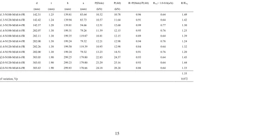
Table 10 shows the comparison of web crippling strength with NAS design strength for an offset hole for the case of flange fastened to the bearing plate. As can be seen, the value of Pm is 1.07 with a corresponding COV of 0.015 i.e. the design strengths obtained from NAS are conservative and reasonable and are on average only 7% lower than the experimental failure loads.
In section 9 of this paper, four new strength reduction factor equations are proposed. These covered the IOF loading condition for centred and offset hole for the case of both flange unfastened and fastened to the bearing plate. It should be noted that although the NAS equation for an offset hole for the case of flange fastened to the bearing plate are conservative and reasonable, the new equation proposed has a lower value of Pm as well as covers a wider range of limits.
9 Proposed strength reduction factors
Evaluation of the experimental and the numerical results shows that the ratios a/h, N/h and x/h are the primary parameters influencing the web crippling behaviour of the sections with web holes. Therefore, based on both the experimental and the numerical results obtained from this study, four strength reduction factor equations (Rp) are proposed using bivariate linear regression analysis for the interior-one-flange loading condition for the centred hole and offset hole, respectively.
For centred hole:
For the case where the flange is unfastened to the bearing plate,
1 ) ( 06 . 0 ) ( 26 . 0 98 .
0 − + ≤
=
h N h
a
Rp (3)
For the case where the flange is fastened to the bearing plate,
1 ) ( 01 . 0 ) ( 06 . 0 95 .
0 − + ≤
=
h N h
a
Rp (4)
For offset hole:
For the case where the flange is unfastened to the bearing plate,
=0.99−0.26( )+0.11( )≤1
h x h
a
Rp (5)
For the case where the flange is fastened to the bearing plate,
=0.99−0.14( )+0.07( )≤1
h x h
a
Rp (6)
The limits for the reduction factor equations (3), (4), (5) and (6) are h/t ≤157.8 , 97
. 120 /t ≤
N , N/h≤1.15,a h/ ≤ 0.8, and 0 90 θ = .
10 Comparison of experimental and numerical results with the proposed
reduction factor
factor (Rp) calculated using Eqs. (3), (4), (5) and (6), as plotted against the ratios a/h and
h/t in Fig. 7 to 10, respectively. Tables 11 to 14 summarize a statistical analysis to define the accuracy of the proposed design equations. It is shown that the proposed reduction factors are generally conservative and agree with the experimental and the numerical results for both cases.
For the centred hole, the mean value of the web crippling reduction factor ratios are 1.01 and 1.01 for the case of flange unfastened and fastened to the bearing plate, respectively. The corresponding values of COV of 0.052 and 0.065, respectively; similarly, the reliability index values (β) are of 2.85 and 2.81, respectively.
For the offset hole, the mean value of the web crippling reduction factor ratios are 1.00 and 1.00 for the case of flange unfastened and fastened to the bearing plate, respectively. The corresponding values of COV of 0.041 and 0.030, respectively; similarly, the reliability index values (β) are of 2.84 and 2.85, respectively. Thus, the proposed strength reduction factor equations are able to predict the influence of the web holes on the web crippling strengths of channel sections for the IOF loading condition.
11 Conclusions
N/h and x/h on the web crippling strength, parametric studies were carried out considering the web holes, the cross-section sizes and the different bearing plate lengths.
The web crippling strengths of cold-formed channel sections without holes obtained from test and finite element analysis were compared with the current design strengths calculated from British Standard [17], Eurocode [18] and NAS [1]. The British Standard and Eurocodes underestimate the web crippling strengths by around 27% and the current design standard NAS design strength does not consider ri/t ratios greater than 3. It is shown that Eurocode and British Standard are very conservative for the web crippling strengths of cold-formed lipped channel sections without web holes.
Only Yu and Davis [2] provide a reduction factor equation for the case of circular web openings located and centred beneath the bearing plate for the case of flange unfastened to the bearing plate. However, the design strengths obtained from Yu and Davis were shown to be very conservative and were on average 35% lower than the experimental failure loads. However, as noted previously, the test arrangement of Yu and Davis did not use back-to-back channel-sections, but instead two channel -sections connected through their lips.
Only the NAS provides reduction factors for the case of circular holes with a horizontal clear distance to the near edge of bearing plate and only for the case of flange fastened to the bearing plate. The design strengths obtained from NAS are 7% lower than the experimental and finite element failure loads, which shows that NAS provides a reasonable prediction for the web crippling behaviour of coldformed steel channel -sections with web holes. In this paper, modified coefficients are proposed that have been shown to cover a wider range of section parameters than the NAS coefficients.
performed to evaluate the reliability of the proposed strength reduction factors. It is shown that the proposed strength reduction factors are generally conservative and agree well with the experimental and numerical results. The proposed strength reduction factors are capable of producing reliable limit state design when calibrated with the resistance factor of 0.85(φ =0.85).
Acknowledgements
References
[1] NAS, North American specification for the design of cold-formed steel structural members, American Iron and Steel Institute, AISI S100-2007, AISI Standard, 2007.
[2] W.W. Yu, C.S. Davis, Cold-formed steel members with perforated elements, Journal of the Structural Division, 99 (1973) 2061-2077.
[3] R.A. LaBoube, R.Schuster, Standard test method for determining the web crippling strength of cold-formed steel members, American Iron and Steel Institute, 2002.
[4] R.A. LaBoube, W.W. Yu, S.U. Deshmukh, C.A. Uphoff, Crippling capacity of web elements with openings, Journal of Structural Engineering, 125 (1999) 137-141.
[5] K.S. Sivakumaran, K.M. Zielonka, Web crippling strength of thin-walled steel members with web opening, Thin-Walled Structures, 8 (1989) 295-319.
[6] F. Zhou, B. Young, Web crippling of aluminium tubes with perforated webs, Engineering Structures, 32 (2010) 1397-1410.
[7] A. Uzzaman, J.B.P. Lim, D. Nash, J. Rhodes, B. Young, Web crippling behaviour of cold-formed steel channel sections with offset web holes subjected to interior-two-flange loading, Thin-Walled Structures, 50 (2012) 76-86.
[9] A. Uzzaman, J.B.P. Lim, D. Nash, J. Rhodes, B. Young, Cold-formed steel sections with web openings subjected to web crippling under two-flange loading conditions-part I: Tests and finite element analysis, Thin-Walled Structures, 56 (2012) 38-48.
[10] A. Uzzaman, J.B.P. Lim, D. Nash, J. Rhodes, B. Young, Cold-formed steel sections with web openings subjected to web crippling under two-flange loading conditions-part II: Parametric study and proposed design equations, Thin-Walled Structures, 56 (2012) 79-87.
[11] P. Natario, N. Silvestre, D. Camotim, Computational modelling of flange crushing in cold-formed steel sections, Thin-Walled Structures, 84 (2014) 393-405.
[12] P. Keerthan, M. Mahendran, E. Steau, Experimental study of web crippling behaviour of hollow flange channel beams under two flange load cases, Thin-Walled Structures, 85 (2014) 207-219.
[13] Y. Chen, XX. Chen, CY. Wang, Experimental and finite element analysis research on cold-formed steel lipped channel beams under web crippling, Thin-walled Structures, 87 (2015) 41-52.
[14] Y. Chen, XX. Chen, CY. Wang, Aluminum tubular sections subjected to web crippling, Thin-Walled Structures, 90 (2015) 49-60.
interior-one-flange loading condition - Part I: Experimental and numerical investigation, Submitted to Thin-walled Structures.
[16] ABAQUS Analysis User’s Manual-Version 6.13-1. ABAQUS Inc., USA, 2013.
[17] BS5950, Structural use of steelwork in buildings, Part 5 Code of practice for the design of cold-formed sections. British Standards Institution, London, 1998.
[18] Eurocode-3, Design of steel structures: Part 1.3: General rules — Supplementary rules for cold-formed thin gauge members and sheeting, in: ENV 1993-1-3, European Committee for Standardization, Brussels, Belgium, 1996.
[19] J. B. P. Lim, D. A. Nethercot, Ultimate strength of bolted moment-connections between cold-formed steel members. Thin Walled Structures, 41 (2001) 1019-1039.
[20] ASCE, Minimum design loads for buildings and other structures, in American Society of Civil Engineers Standard, New York, 2005.
Table 1
Dimensions and web crippling strengths predicted from finite element analysis in parametric study of a/h for centred hole where flange unfastened to bearing
plate
Specimen Web Flange Lip Thickness Length FEA load per web, PFEA
d bf bl t L A0 A0.2 A0.4 A0.6 A0.8
(mm) (mm) (mm) (mm) (mm) (kN) (kN) (kN) (kN) (kN)
142x60x13-t1.3-N100-FR 141.82 60.63 13.66 1.27 720.0 10.69 10.58 10.51 10.04 -
142x60x13-t4.0-N100-FR 141.82 60.63 13.66 4.00 720.0 87.16 85.68 80.68 74.50 -
142x60x13-t6.0-N100-FR 141.82 60.63 13.66 6.00 720.0 160.59 156.70 148.49 132.61 -
142x60x13-t1.3-N120-FR 142.24 60.37 13.90 1.27 740.0 11.52 11.40 11.23 10.43 9.23
142x60x13-t4.0-N120-FR 142.24 60.37 13.90 4.00 740.0 91.49 89.63 84.81 79.24 67.83
142x60x13-t6.0-N120-FR 142.24 60.37 13.90 6.00 740.0 162.26 158.41 150.74 133.95 110.43
142x60x13-t1.3-N150-FR 142.40 59.79 13.28 1.28 770.0 12.44 12.27 11.87 10.83 9.71
142x60x13-t4.0-N150-FR 142.40 59.79 13.28 4.00 770.0 92.04 90.66 85.68 80.80 69.39
142x60x13-t6.0-N150-FR 142.40 59.79 13.28 6.00 770.0 165.70 162.12 152.18 135.05 111.77
202x65x15-t1.4-N100-FR 202.04 64.79 14.78 1.39 899.2 12.17 12.14 11.75 10.50 -
202x65x15-t4.0-N100-FR 202.04 64.79 14.78 4.00 899.2 89.93 89.25 85.79 - -
202x65x15-t6.0-N100-FR 202.04 64.79 14.78 6.00 899.2 181.61 177.52 165.88 - -
202x65x15-t1.4-N120-FR 202.00 65.00 14.73 1.39 920.0 12.58 12.52 11.95 10.66 -
202x65x15-t4.0-N120-FR 202.00 65.00 14.73 4.00 920.0 93.90 93.14 88.66 80.93 -
202x65x15-t6.0-N120-FR 202.00 65.00 14.73 6.00 920.0 184.75 181.32 171.54 156.88 -
202x65x15-t1.4-N150-FR 202.01 65.04 14.98 1.39 950.0 13.05 12.90 12.18 11.02 -
202x65x15-t4.0-N150-FR 202.01 65.04 14.98 4.00 950.0 99.30 97.98 92.61 86.22 -
202x65x15-t6.0-N150-FR 202.01 65.04 14.98 6.00 950.0 184.82 181.63 171.91 157.33 -
302x90x18-t2.0-N100-FR 303.18 87.91 18.83 1.98 1200.0 24.34 24.33 - 22.44 -
302x90x18-t4.0-N100-FR 303.18 87.91 18.83 4.00 1200.0 92.70 92.67 - - -
302x90x18-t6.0-N100-FR 303.18 87.91 18.83 6.00 1200.0 195.28 194.05 - - -
302x90x18-t2.0-N120-FR 303.07 87.95 18.26 1.98 1221.0 26.00 25.98 25.61 22.68 -
302x90x18-t6.0-N120-FR 303.07 87.95 18.26 6.00 1221.0 202.30 200.43 193.32 - -
302x90x18-t2.0-N150-FR 303.03 88.54 18.97 1.99 1249.0 27.99 27.83 26.49 23.57 -
302x90x18-t4.0-N150-FR 303.03 88.54 18.97 4.00 1249.0 104.14 103.94 99.79 - -
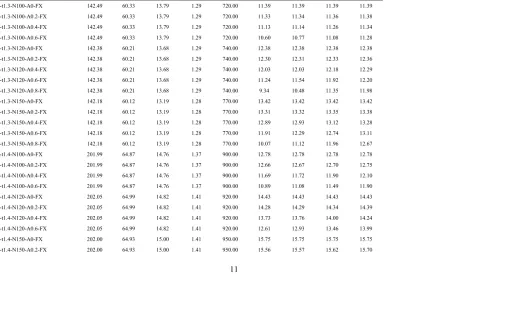
Table 2
Dimensions and web crippling strengths predicted from finite element analysis in parametric study of a/h for centred hole where flange fastened to bearing
plate
Specimen Web Flange Lip Thickness Length FEA load per web, PFEA
d bf bl t L A0 A0.2 A0.4 A0.6 A0.8
(mm) (mm) (mm) (mm) (mm) (kN) (kN) (kN) (kN) (kN)
142x60x13-t1.3-N100-FX 142.49 60.33 13.79 1.29 720.00 11.39 11.38 11.33 10.90 -
142x60x13-t4.0-N100-FX 142.49 60.33 13.79 4.00 720.00 100.03 99.33 94.85 86.22 -
142x60x13-t6.0-N100-FX 142.49 60.33 13.79 6.00 720.00 199.22 198.49 189.76 172.87 -
142x60x13-t1.3-N120-FX 142.38 60.21 13.68 1.29 740.00 12.38 12.37 12.36 11.44 10.13
142x60x13-t4.0-N120FX 142.38 60.21 13.68 4.00 740.00 108.61 107.69 101.95 93.60 83.85
142x60x13-t6.0-N120-FX 142.38 60.21 13.68 6.00 740.00 207.07 205.72 197.93 182.20 159.54
142x60x13-t1.3-N150-FX 142.18 60.12 13.19 1.28 770.00 13.42 13.40 13.04 11.96 10.69
142x60x13-t4.0-N150-FX 142.18 60.12 13.19 4.00 770.00 117.53 116.51 111.01 102.81 91.82
142x60x13-t6.0-N150-FX 142.18 60.12 13.19 6.00 770.00 208.38 207.69 202.21 189.29 168.99
202x65x15-t1.4-N100-FX 201.99 64.87 14.76 1.37 900.00 12.78 12.77 12.64 12.33 -
202x65x15-t4.0-N100-FX 201.99 64.87 14.76 4.00 900.00 102.59 102.07 99.58 - -
202x65x15-t6.0-N100-FX 201.99 64.87 14.76 6.00 900.00 219.11 216.73 206.27 - -
202x65x15-t1.4-N120-FX 202.05 64.99 14.82 1.41 920.00 14.43 14.41 14.16 12.97 -
202x65x15-t4.0-N120-FX 202.05 64.99 14.82 4.00 920.00 109.97 109.34 104.83 93.89 -
202x65x15-t6.0-N120-FX 202.05 64.99 14.82 6.00 920.00 233.82 231.12 217.95 196.65 -
202x65x15-t1.4-N150-FX 202.00 64.93 15.00 1.41 950.00 15.75 15.74 15.62 13.86 -
202x65x15-t4.0-N150-FX 202.00 64.93 15.00 4.00 950.00 121.32 119.46 112.05 101.57 -
202x65x15-t6.0-N150-FX 202.00 64.93 15.00 6.00 950.00 256.55 249.05 234.17 212.72 -
302x90x18-t2.0-N100-FX 303.20 88.24 18.66 1.96 1199.00 25.16 25.15 - - -
302x90x18-t4.0-N100-FX 303.20 88.24 18.66 4.00 1199.00 100.74 100.54 - - -
302x90x18-t6.0-N100-FX 303.20 88.24 18.66 6.00 1199.00 219.79 218.66 - - -
302x90x18-t2.0-N120-FX 303.50 88.53 18.36 1.93 1219.00 26.34 26.33 26.32 - -
302x90x18-t4.0-N120-FX 303.50 88.53 18.36 4.00 1219.00 108.14 107.98 107.64 - -
302x90x18-t2.0-N150-FX 303.85 88.71 18.41 1.90 1248.33 28.09 27.82 27.43 - -
302x90x18-t4.0-N150-FX 303.85 88.71 18.41 4.00 1248.33 118.16 118.05 116.99 - -
Table 3
Dimensions and web crippling strengths predicted from finite element analysis in parametric study of a/h for offset hole where flange unfastened to bearing
plate
Specimen Web Flange Lip Thickness Length FEA load per web, PFEA
d bf bl t L A0 A0.2 A0.4 A0.6
(mm) (mm) (mm) (mm) (mm) (kN) (kN) (kN) (kN)
142x60x13-t1.3-N100-FR 141.82 60.63 13.66 1.27 720.0 10.69 10.65 10.64 10.59
142x60x13-t4.0-N100-FR 141.82 60.63 13.66 4.00 720.0 87.16 86.93 83.72 83.59
142x60x13-t6.0-N100-FR 141.82 60.63 13.66 6.00 720.0 157.71 157.52 156.10 155.62
142x60x13-t1.3-N120-FR 142.24 60.37 13.90 1.27 740.0 11.52 11.47 11.34 11.24
142x60x13-t4.0-N120-FR 142.24 60.37 13.90 4.00 740.0 91.49 91.34 90.91 89.75
142x60x13-t6.0-N120-FR 142.24 60.37 13.90 6.00 740.0 159.31 159.26 157.70 154.43
142x60x13-t1.3-N150-FR 142.40 59.79 13.28 1.28 770.0 12.44 12.42 12.34 12.32
142x60x13-t4.0-N150-FR 142.40 59.79 13.28 4.00 770.0 92.04 91.73 91.11 90.10
142x60x13-t6.0-N150-FR 142.40 59.79 13.28 6.00 770.0 159.50 159.20 158.55 156.21
202x65x15-t1.4-N100-FR 202.04 64.79 14.78 1.39 899.2 12.17 11.96 11.82 11.53
202x65x15-t4.0-N100-FR 202.04 64.79 14.78 4.00 899.2 89.93 89.67 88.83 88.27
202x65x15-t6.0-N100-FR 202.04 64.79 14.78 6.00 899.2 181.61 181.47 178.86 173.25
202x65x15-t1.4-N120-FR 202.00 65.00 14.73 1.39 920.0 12.76 12.55 12.48 11.86
202x65x15-t4.0-N120-FR 202.00 65.00 14.73 4.00 920.0 93.90 93.57 92.58 91.98
202x65x15-t6.0-N120-FR 202.00 65.00 14.73 6.00 920.0 184.75 183.96 178.96 173.50
202x65x15-t1.4-N150-FR 202.01 65.04 14.98 1.39 950.0 14.24 13.96 13.77 12.99
202x65x15-t4.0-N150-FR 202.01 65.04 14.98 4.00 950.0 99.30 98.96 97.63 96.97
202x65x15-t6.0-N150-FR 202.01 65.04 14.98 6.00 950.0 185.68 184.81 179.99 177.06
302x90x18-t2.0-N100-FR 303.18 87.91 18.83 1.98 1200.0 24.34 23.58 23.34 22.81
302x90x18-t4.0-N100-FR 303.18 87.91 18.83 2.00 1200.0 92.70 92.46 91.60 89.71
302x90x18-t6.0-N100-FR 303.18 87.91 18.83 4.00 1200.0 195.28 194.57 191.82 183.03
302x90x18-t2.0-N120-FR 303.07 87.95 18.26 1.98 1221.0 25.50 25.36 24.77 23.28
302x90x18-t4.0-N120-FR 303.07 87.95 18.26 2.00 1221.0 95.95 97.35 96.14 91.84
302x90x18-t2.0-N150-FR 303.03 88.54 18.97 1.99 1249.0 27.99 27.64 27.11 -
302x90x18-t4.0-N150-FR 303.03 88.54 18.97 2.00 1249.0 104.14 103.55 102.32 -
Table 4
Dimensions and web crippling strengths predicted from finite element analysis in parametric study of a/h for offset hole where flange fastened to bearing plate
Specimen Web Flange Lip Thickness Length FEA load per web, PFEA
d bf bl t L A0 A0.2 A0.4 A0.6
(mm) (mm) (mm) (mm) (mm) (kN) (kN) (kN) (kN)
142x60x13-t1.3-N100-FX 142.49 60.33 13.79 1.29 720.00 11.39 11.38 11.38 11.36
142x60x13-t4.0-N100-FX 142.49 60.33 13.79 4.00 720.00 100.03 100.00 99.97 99.96
142x60x13-t6.0-N100-FX 142.49 60.33 13.79 6.00 720.00 199.22 198.95 198.27 195.61
142x60x13-t1.3-N120-FX 142.38 60.21 13.68 1.29 740.00 12.38 12.37 12.35 12.33
142x60x13-t4.0-N120-FX 142.38 60.21 13.68 4.00 740.00 108.61 108.58 108.52 108.44
142x60x13-t6.0-N120-FX 142.38 60.21 13.68 6.00 740.00 207.07 206.59 205.25 199.02
142x60x13-t1.3-N150-FX 142.18 60.12 13.19 1.28 740.00 13.42 13.41 13.38 13.35
142x60x13-t4.0-N150-FX 142.18 60.12 13.19 4.00 740.00 117.53 117.47 117.32 116.89
142x60x13-t6.0-N150-FX 142.18 60.12 13.19 6.00 740.00 208.38 207.53 205.39 198.60
202x65x15-t1.4-N100-FX 201.99 64.87 14.76 1.41 900.00 12.78 12.77 12.71 12.62
202x65x15-t4.0-N100-FX 201.99 64.87 14.76 4.00 900.00 102.59 102.53 102.44 102.32
202x65x15-t6.0-N100-FX 201.99 64.87 14.76 6.00 900.00 219.11 219.02 218.81 218.48
202x65x15-t1.4-N120-FX 202.05 64.99 14.82 1.37 920.00 14.43 14.42 14.34 14.19
202x65x15-t4.0-N120-FX 202.05 64.99 14.82 4.00 920.00 109.97 109.92 109.80 109.65
202x65x15-t6.0-N120-FX 202.05 64.99 14.82 6.00 920.00 233.82 233.68 233.27 232.37
202x65x15-t1.4-N150-FX 202.00 64.93 15.00 1.41 950.00 15.75 15.74 15.64 15.38
202x65x15-t4.0-N150-FX 202.00 64.93 15.00 4.00 950.00 121.32 120.67 120.52 120.16
202x65x15-t6.0-N150-FX 202.00 64.93 15.00 6.00 950.00 256.55 251.54 250.68 247.30
302x90x18-t2.0N-100-FX 303.20 88.24 18.66 1.96 1199.00 25.16 25.14 25.09 24.87
302x90x18-t4.0-N100-FX 303.20 88.24 18.66 4.00 1199.00 100.74 100.71 100.65 100.55
302x90x18-t6.0-N100-FX 303.20 88.24 18.66 6.00 1199.00 219.79 219.73 219.65 219.50
302x90x18-t2.0-N120-FX 303.50 88.53 18.36 1.93 1219.00 26.34 26.32 26.21 25.95
302x90x18-t4.0-N120-FX 303.50 88.53 18.36 4.00 1219.00 108.14 108.11 108.03 107.88
302x90x18-t6.0N-120-FX 303.50 88.53 18.36 6.00 1219.00 236.27 236.24 236.13 235.97
302x90x18-t4.0-N150-FX 303.85 88.71 18.41 4.00 1248.33 118.16 118.13 118.08 -
Table 5
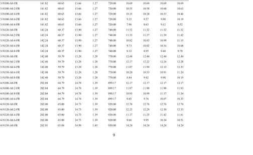
Dimensions and web crippling strengths predicted from finite element analysis in parametric study of x/h for offset hole where flange unfastened to bearing
plate
Specimen Web Flange Lip Thickness Length FEA load per web, PFEA
d bf bl t L X0 X0.2 X0.4 X0.6
(mm) (mm) (mm) (mm) (mm) (kN) (kN) (kN) (kN)
142x60x13-t1.3-N100-A0-FR 141.82 60.63 13.66 1.27 720.00 10.69 10.69 10.69 10.69
142x60x13-t1.3-N100-A0.2-FR 141.82 60.63 13.66 1.27 720.00 10.55 10.58 10.60 10.63
142x60x13-t1.3-N100-A0.4-FR 141.82 60.63 13.66 1.27 720.00 10.15 10.20 10.33 10.46
142x60x13-t1.3-N100-A0.6-FR 141.82 60.63 13.66 1.27 720.00 9.35 9.57 9.90 10.19
142x60x13-t1.3-N100-A0.8-FR 141.82 60.63 13.66 1.27 720.00 7.96 8.63 9.12 9.52
142x60x13-t1.3-N120-A0-FR 142.24 60.37 13.90 1.27 740.00 11.52 11.52 11.52 11.52
142x60x13-t1.3-N120-A0.2-FR 142.24 60.37 13.90 1.27 740.00 11.33 11.37 11.39 11.42
142x60x13-t1.3-N120-A0.4-FR 142.24 60.37 13.90 1.27 740.00 10.82 10.83 10.99 11.15
142x60x13-t1.3-N120-A0.6-FR 142.24 60.37 13.90 1.27 740.00 9.73 10.02 10.34 10.68
142x60x13-t1.3-N120-A0.8-FR 142.24 60.37 13.90 1.27 740.00 8.32 8.95 9.44 9.78
142x60x13-t1.3-N150-A0-FR 142.40 59.79 13.28 1.28 770.00 12.44 12.44 12.44 12.44
142x60x13-t1.3-N150-A0.2-FR 142.40 59.79 13.28 1.28 770.00 12.17 12.22 12.24 12.28
142x60x13-t1.3-N150-A0.4-FR 142.40 59.79 13.28 1.28 770.00 11.87 11.94 12.13 12.33
142x60x13-t1.3-N150-A0.6-FR 142.40 59.79 13.28 1.28 770.00 10.20 10.53 10.91 11.24
142x60x13-t1.3-N150-A0.8-FR 142.40 59.79 13.28 1.28 770.00 8.84 9.42 9.90 10.19
202x65x15-t1.4-N100-A0-FR 202.04 64.79 14.78 1.39 899.17 12.17 12.17 12.17 12.17
202x65x15-t1.4-N100-A0.2-FR 202.04 64.79 14.78 1.39 899.17 11.87 11.90 11.90 11.93
202x65x15-t1.4-N100-A0.4-FR 202.04 64.79 14.78 1.39 899.17 10.93 10.99 11.17 11.34
202x65x15-t1.4-N100-A0.6-FR 202.04 64.79 14.78 1.39 899.17 9.45 9.76 10.07 10.35
202x65x15-t1.4-N120-A0-FR 202.00 65.00 14.73 1.39 920.00 12.76 12.76 12.76 12.76
202x65x15-t1.4-N120-A0.2-FR 202.00 65.00 14.73 1.39 920.00 12.23 12.29 12.30 12.33
202x65x15-t1.4-N120-A0.4-FR 202.00 65.00 14.73 1.39 920.00 11.17 11.25 11.42 11.61
202x65x15-t1.4-N120-A0.6-FR 202.00 65.00 14.73 1.39 920.00 9.66 9.95 10.24 10.51
202x65x15-t1.4-N150-A0.2-FR 202.01 65.04 14.98 1.45 950.00 13.77 13.85 13.86 13.90
202x65x15-t1.4-N150-A0.4-FR 202.01 65.04 14.98 1.45 950.00 12.59 12.67 12.85 13.04
202x65x15-t1.4-N150-A0.6-FR 202.01 65.04 14.98 1.45 950.00 11.00 11.29 11.58 11.83
302x90x18-t2.0-N100-A0-FR 303.18 87.91 18.83 1.98 1200.00 24.34 24.34 24.34 24.34
302x90x18-t2.0-N100-A0.2-FR 303.18 87.91 18.83 1.98 1200.00 24.09 24.13 24.16 24.22
302x90x18-t2.0-N120-A0-FR 303.07 87.95 18.26 1.96 1221.00 25.50 25.50 25.50 25.50
302x90x18-t2.0-N120-A0.2-FR 303.07 87.95 18.26 1.96 1221.00 25.13 25.15 25.19 25.25
302x90x18-t2.0-N120-A0.4-FR 303.07 87.95 18.26 1.96 1221.00 23.07 23.24 23.62 24.12
302x90x18-t2.0-N120-A0.6-FR 303.07 87.95 18.26 1.96 1221.00 19.65 20.38 21.37 22.48
302x90x18-t2.0-N150-A0-FR 303.03 88.54 18.97 1.99 1249.00 27.99 27.99 27.99 27.99
302x90x18-t2.0-N150-A0.2-FR 303.03 88.54 18.97 1.99 1249.00 27.25 27.27 27.32 27.42
302x90x18-t2.0-N150-A0.4-FR 303.03 88.54 18.97 1.99 1249.00 24.65 24.82 25.26 25.84
Table 6
Dimensions and web crippling strengths predicted from finite element analysis in parametric study of x/h for offset hole where flange fastened to bearing
plate
Specimen Web Flange Lip Thickness Length FEA load per web, PFEA
d bf bl t L X0 X0.2 X0.4 X0.6
(mm) (mm) (mm) (mm) (mm) (kN) (kN) (kN) (kN)
142x60x13-t1.3-N100-A0-FX 142.49 60.33 13.79 1.29 720.00 11.39 11.39 11.39 11.39
142x60x13-t1.3-N100-A0.2-FX 142.49 60.33 13.79 1.29 720.00 11.33 11.34 11.36 11.38
142x60x13-t1.3-N100-A0.4-FX 142.49 60.33 13.79 1.29 720.00 11.13 11.14 11.26 11.34
142x60x13-t1.3-N100-A0.6-FX 142.49 60.33 13.79 1.29 720.00 10.60 10.77 11.08 11.28
142x60x13-t1.3-N120-A0-FX 142.38 60.21 13.68 1.29 740.00 12.38 12.38 12.38 12.38
142x60x13-t1.3-N120-A0.2-FX 142.38 60.21 13.68 1.29 740.00 12.30 12.31 12.33 12.36
142x60x13-t1.3-N120-A0.4-FX 142.38 60.21 13.68 1.29 740.00 12.03 12.03 12.18 12.29
142x60x13-t1.3-N120-A0.6-FX 142.38 60.21 13.68 1.29 740.00 11.24 11.54 11.92 12.20
142x60x13-t1.3-N120-A0.8-FX 142.38 60.21 13.68 1.29 740.00 9.34 10.48 11.35 11.98
142x60x13-t1.3-N150-A0-FX 142.18 60.12 13.19 1.28 770.00 13.42 13.42 13.42 13.42
142x60x13-t1.3-N150-A0.2-FX 142.18 60.12 13.19 1.28 770.00 13.31 13.32 13.35 13.38
142x60x13-t1.3-N150-A0.4-FX 142.18 60.12 13.19 1.28 770.00 12.89 12.93 13.12 13.28
142x60x13-t1.3-N150-A0.6-FX 142.18 60.12 13.19 1.28 770.00 11.91 12.29 12.74 13.11
142x60x13-t1.3-N150-A0.8-FX 142.18 60.12 13.19 1.28 770.00 10.07 11.12 11.96 12.67
202x65x15-t1.4-N100-A0-FX 201.99 64.87 14.76 1.37 900.00 12.78 12.78 12.78 12.78
202x65x15-t1.4-N100-A0.2-FX 201.99 64.87 14.76 1.37 900.00 12.66 12.67 12.70 12.75
202x65x15-t1.4-N100-A0.4-FX 201.99 64.87 14.76 1.37 900.00 11.69 11.72 11.90 12.10
202x65x15-t1.4-N100-A0.6-FX 201.99 64.87 14.76 1.37 900.00 10.89 11.08 11.49 11.90
202x65x15-t1.4-N120-A0-FX 202.05 64.99 14.82 1.41 920.00 14.43 14.43 14.43 14.43
202x65x15-t1.4-N120-A0.2-FX 202.05 64.99 14.82 1.41 920.00 14.28 14.29 14.34 14.39
202x65x15-t1.4-N120-A0.4-FX 202.05 64.99 14.82 1.41 920.00 13.73 13.76 14.00 14.24
202x65x15-t1.4-N120-A0.6-FX 202.05 64.99 14.82 1.41 920.00 12.61 12.93 13.46 13.99
202x65x15-t1.4-N150-A0-FX 202.00 64.93 15.00 1.41 950.00 15.75 15.75 15.75 15.75
202x65x15-t1.4-N150-A0.4-FX 202.00 64.93 15.00 1.41 950.00 14.78 14.85 15.16 15.46
202x65x15-t1.4-N150-A0.6-FX 202.00 64.93 15.00 1.41 950.00 13.42 13.84 14.44 15.07
302x90x18-t2.0-N100-A0-FX 303.20 88.24 18.66 1.96 1199.00 25.16 25.16 25.16 25.16
302x90x18-t2.0-N100-A0.2-FX 303.20 88.24 18.66 1.96 1199.00 25.07 25.11 25.14 25.15
302x90x18-t2.0-N120-A0-FX 303.50 88.53 18.36 1.93 1219.00 26.34 26.34 26.34 26.34
302x90x18-t2.0-N120-A0.2-FX 303.50 88.53 18.36 1.93 1219.00 26.26 26.26 26.28 26.30
302x90x18-t2.0-N120-A0.4-FX 303.50 88.53 18.36 1.93 1219.00 24.45 24.65 25.26 25.34
302x90x18-t2.0-N120-A0.6-FX 303.50 88.53 18.36 1.93 1219.00 23.52 24.32 24.49 24.55
302x90x18-t2.0-N150-A0-FX 303.85 88.71 18.41 1.90 1248.33 28.09 28.09 28.09 28.09
302x90x18-t2.0-N150-A0.2-FX 303.85 88.71 18.41 1.90 1248.33 27.94 27.96 28.00 28.02
302x90x18-t2.0-N150-A0.4-FX 303.85 88.71 18.41 1.90 1248.33 26.59 26.88 27.70 27.84
Table 7
Comparison of experimental and numerical results with design strength for case of flange unfastened to bearing plate
Specimen Web
slenderness
Bearing length
ratio
Bearing length
ratio
Inside bend radius
ratio
Failure load per web (PEXP)
Web crippling strength per web predicted from current
design codes
Comparison
h/t N/t N/h ri/t P PBS PEuro. PNAS P/PBS P/PEuro P/NAS
(kN) (kN) (kN) (kN)
142x60x13-t1.3-N100-A0-FR 109.67 78.74 0.72 3.78 10.78 9.26 9.90 10.63 1.16 1.09 -
142x60x13-t1.3-N120-A0-FR 110.00 94.49 0.86 3.78 11.64 9.92 10.96 11.20 1.17 1.06 -
142x60x13-t1.3-N150-A0-FR 109.25 117.19 1.07 3.75 12.60 11.07 12.73 12.16 1.14 0.99 -
202x65x15-t1.4-N100-A0-FR 144.41 72.46 0.50 3.62 12.15 10.73 11.33 14.39 1.13 1.07 -
202x65x15-t1.4-N120-A0-FR 144.38 86.96 0.60 3.62 12.98 11.46 12.50 15.13 1.13 1.04 -
202x65x15-t1.4-N150-A0-FR 144.38 108.70 0.75 3.62 14.51 12.54 14.25 16.14 1.16 1.02 -
302x90x18-t2.0-N100-A0-FR 157.57 52.63 0.33 2.63 24.57 18.63 18.57 24.84 1.32 1.32 0.99
302x90x18-t2.0-N120-A0-FR 157.51 63.16 0.40 2.63 25.16 19.63 20.19 26.03 1.28 1.25 0.97
302x90x18-t2.0-N150-A0-FR 155.01 77.72 0.50 2.59 28.24 21.84 23.31 28.57 1.29 1.21 0.99
Mean, Pm 1.20 1.12 0.98
Coefficient of variation, Vp 0.063 0.103 0.013
Table 8
Comparison of experimental and numerical results with design strength for case of flange fastened to bearing plate
Specimen Web
slenderness
Bearing length
ratio
Bearing length
ratio
Inside bend radius
ratio
Failure load per web (PEXP)
Web crippling strength per web predicted from current
design codes
Comparison
h/t N/t N/h ri/t P PBS PEuro. PNAS P/PBS P/PEuro P/PNAS
(kN) (kN) (kN) (kN)
142x60x13-t1.3-N100-A0-FX 110.19 78.74 0.71 3.78 11.14 9.25 9.89 10.63 1.20 1.13 -
142x60x13-t1.3-N120-A0-FX 110.11 94.49 0.86 3.78 12.33 9.91 10.96 11.19 1.24 1.13 -
142x60x13-t1.3-N150-A0-FX 109.08 117.19 1.07 3.75 13.48 11.08 12.73 12.16 1.22 1.06 -
202x65x15-t1.4-N100-A0-FX 144.37 72.46 0.50 3.62 13.35 10.73 11.33 14.39 1.24 1.18 -
202x65x15-t1.4-N120-A0-FX 144.41 86.96 0.60 3.62 14.60 11.45 12.50 15.13 1.27 1.17 -
202x65x15-t1.4-N150-A0-FX 144.38 108.70 0.75 3.62 16.14 12.54 14.25 16.14 1.29 1.13 -
302x90x18-t2.0-N100-A0-FX 157.58 52.63 0.33 2.63 25.26 18.62 18.57 24.84 1.36 1.36 1.02
302x90x18-t2.0-N120-A0-FX 157.74 63.16 0.40 2.63 26.40 19.62 20.18 26.03 1.35 1.31 1.01
302x90x18-t2.0-N150-A0-FX 155.43 77.72 0.50 2.59 28.13 21.82 23.29 28.57 1.29 1.21 0.98
Mean, Pm 1.27 1.18 1.01
Table 9
Comparison of web crippling strength with Yu and Davis [6] design strength for centred hole where flange unfastened to bearing plate
Specimen Web Thickness
Depth of the flat portion of web Holes Failure load per web with holes Failure load per web without holes Reduction factor from exp. Factored resistance from Yu and Davis [6]
Comparison with factor
resistance
d t h a P(Hole) P(A0) R=P(Hole)/P(A0) RYu= 1.0-0.6(a/h) R/RYu
(mm) (mm) (mm) (mm) (kN) (kN)
142x60x13-t1.3-N100-MA0.6-FR 142.31 1.25 139.81 83.64 10.32 10.78 0.96 0.64 1.49
142x60x13-t1.3-N120-MA0.6-FR 142.42 1.24 139.94 83.73 10.57 11.64 0.91 0.64 1.42
142x60x13-t1.3-N150-MA0.4-FR 142.37 1.28 139.81 54.66 12.51 12.60 0.99 0.77 1.30
202x65x15-t1.4-N100-MA0.4-FR 202.07 1.38 199.31 79.26 11.59 12.15 0.95 0.76 1.25
202x65x15-t1.4-N100-MA0.6-FR 202.11 1.38 199.35 119.07 10.81 12.15 0.89 0.64 1.39
202x65x15-t1.4-N120-MA0.4-FR 202.00 1.38 199.24 79.32 12.21 12.98 0.94 0.76 1.24
202x65x15-t1.4-N120-MA0.6-FR 202.26 1.38 199.50 119.39 10.95 12.98 0.84 0.64 1.32
202x65x15-t1.4-N150-MA0.4-FR 202.00 1.38 199.24 79.32 13.23 14.51 0.91 0.76 1.20
302x90x18-t2.0-N100-MA0.6-FR 303.05 1.90 299.25 179.00 22.85 24.57 0.93 0.64 1.45
302x90x18-t2.0-N120-MA0.6-FR 303.03 1.90 299.23 179.00 23.29 25.16 0.93 0.64 1.44
302x90x18-t2.0-N150-MA0.6-FR 303.63 1.90 299.83 178.66 24.18 28.24 0.86 0.64 1.33
Mean, Pm 1.35
Table 10
Comparison of web crippling strength with NAS design strength for offset hole where flange fastened to bearing plate Specimen Web slenderness Hole diameter ratio Hole distance ratio Distance between holes Distance between end of member and end of
holes Failure load per web with holes Failure load per web without holes Reduction factor
from exp. Factored resistance
Comparison with factor
resistance
h/t a/h x/h dholes ded P(Hole) P(A0) R=P(Hole)/P(A0) RNAS
=0.9-0.047(a/h)+0.053(x/h) R/RNAS
h/t ≤ 200 a/h < 0.7 dholes≥ 457 ≥ d
(mm) (mm) (kN) (kN)
202x65x15-t1.4-N120-A0.2-FX 144.41 0.2 0.77 466.52 206.82 14.41 14.43 1.00 0.93 1.07
202x65x15-t4.0-N120-A0.2-FX 48.51 0.2 0.79 465.47 207.87 109.34 109.97 0.99 0.93 1.07
202x65x15-t6.0-N120-A0.2-FX 31.67 0.2 0.81 464.67 208.67 231.12 233.82 0.99 0.93 1.06
202x65x15-t4.0-N150-A0.2-FX 48.5 0.2 0.82 505.47 202.87 119.46 121.32 0.98 0.93 1.05
202x65x15-t6.0-N150-A0.2-FX 31.67 0.2 0.83 504.67 203.67 249.05 256.55 0.97 0.93 1.04
302x90x18-t2.0-N120-A0.2-X0.6-FX 157.74 0.2 0.6 539.49 309.83 26.30 26.34 1.00 0.92 1.08
302x90x18-t2.0-N120-A0.4-X0.4-FX 157.74 0.4 0.4 479.46 309.91 25.26 26.34 0.96 0.90 1.06
302x90x18-t2.0-N150-A0.2-X0.6-FX 155.43 0.2 0.6 569.83 309.33 28.02 28.09 1.00 0.92 1.08
302x90x18-t2.0-N150-A0.4-X0.4-FX 155.43 0.4 0.4 509.68 309.48 27.70 28.09 0.99 0.90 1.09
Mean, Pm 1.07
[image:36.595.78.761.98.363.2]Table 11
Statistical analysis for comparison of strength reduction factor for centred hole where flange unfastened to bearing plate
Statistical parameters R (Test & FEA) / Rp (0.98-0.26 (a/h)+0.06 (N/h))
Number of data 103
Mean, Pm 1.01
Coefficient of variation, Vp 0.052
Reliability index, β 2.85
Resistance factor,
φ
0.85Table 12
Statistical analysis for comparison of strength reduction factor for centred hole where flange fastened to bearing plate
Statistical parameters R (Test & FEA) / Rp (0.95-0.06 (a/h)+0.01 (N/h))
Number of data 100
Mean, Pm 1.01
Coefficient of variation, Vp 0.065
Reliability index, β 2.81
[image:37.595.78.613.86.202.2] [image:37.595.81.595.247.359.2]Table 13
Statistical analysis for comparison of strength reduction factor for offset hole where flange unfastened to bearing plate
Statistical parameters R (Test & FEA) / Rp (0.99-0.26(a/h)+0.11 (x/h))
Number of data 253
Mean, Pm 1.00
Coefficient of variation, Vp 0.041
Reliability index, β 2.84
Resistance factor,
φ
0.85Table 14
Statistical analysis for comparison of strength reduction factor for offset hole where flange fastened to bearing plate
Statistical parameters R (Test & FEA) / Rp (0.99-0.14 (a/h)+0.07 (x/h))
Number of data 249
Mean, Pm 1.00
Coefficient of variation, Vp 0.030
Reliability index, β 2.85
[image:38.595.79.593.247.359.2]
(a) With holes centred under bearing plate
d a
N
L
≥ 1.5 d ≥ 1.5 d
(b) With holes offset from bearing plate
Fig.1 Interior-one-flange loading condition
d a
N
L
x x
≥ 1.5 d ≥ 1.5 d
[image:40.595.71.641.77.300.2]
Fig.2 Definition of symbols d h
bf ri a
[image:41.595.182.364.194.404.2](a) Flange unfastened case
(b)Flange fastened case
Fig.3 Variation in reduction factors with a/h for C142 section with centred hole
0.0 0.2 0.4 0.6 0.8 1.0 1.2 1.4
0.0 0.2 0.4 0.6 0.8 1.0
R
a/hRatio
N100-t1.3-FR N100-t4.0-FR N100-t6.0-FR
N120-t1.3-FR N120-t4.0-FR N120-t6.0-FR
N150-t1.3-FR N150-t4.0-FR N150-t6.0-FR
0.0 0.2 0.4 0.6 0.8 1.0 1.2 1.4
0.0 0.2 0.4 0.6 0.8 1.0
R
a/h Ratio
N100-t1.3-FX N100-t4.0-FX N100-t6.0-FX
N120-t1.3-FX N120-t4.0-FX N120-t6.0-FX
[image:42.595.97.502.79.696.2](a) Flange unfastened case
(b) Flange fastened case
Fig.4 Variation in reduction factors with N/h for C142 section with centred hole
0.0 0.2 0.4 0.6 0.8 1.0 1.2 1.4
0.6 0.7 0.8 0.9 1.0 1.1 1.2
R
N/hRatio
t1.3-A0.2-FR t1.3-A0.4-FR t1.3-A0.6-FR
t4.0-A0.2-FR t4.0-A0.4-FR t4.0-A0.6-FR
t6.0-A0.2-FR t6.0-A0.4-FR t6.0-A0.6-FR
0.0 0.2 0.4 0.6 0.8 1.0 1.2 1.4
0.6 0.7 0.8 0.9 1.0 1.1 1.2
R
N/h Ratio
t1.3-A0.2-FX t1.3-A0.4-FX t1.3-A0.6-FX
t4.0-A0.2-FX t4.0-A0.4-FX t4.0-A0.6-FX
[image:43.595.96.502.93.696.2](a) Flange unfastened case
(b) Flange fastened case
Fig.5 Variation in reduction factors with a/h for C142 section with offset hole
0.0 0.2 0.4 0.6 0.8 1.0 1.2 1.4
0.0 0.2 0.4 0.6 0.8 1.0
R
a/hRatio
N100-t1.3-FR N100-t4.0-FR N100-t6.0-FR
N120-t1.3-FR N120-t4.0-FR N120-t6.0-FR
N150-t1.3-FR N150-t4.0-FR N150-t6.0-FR
0.0 0.2 0.4 0.6 0.8 1.0 1.2 1.4
0.0 0.2 0.4 0.6 0.8 1.0
R
a/hRatio
N100-t1.3-FX N100-t4.0-FX N100-t6.0-FX
N120-t1.3-FX N120-t4.0-FX N120-t6.0-FX
[image:44.595.93.506.91.659.2](a) Flange unfastened case
(b) Flange fastened case
Fig.6 Variation in reduction factors with x/h for C142 section with offset hole
0.0 0.2 0.4 0.6 0.8 1.0 1.2 1.4
0.0 0.2 0.4 0.6 0.8 1.0
R
x/hRatio
N100-A0.2-FR N100-A0.4-FR N100-A0.6-FR
N120-A0.2 N120-A0.4-FR N120-A0.6-FR
N150-A0.2-FR N150-A0.4-FR N150-A0.6-FR
0.0 0.2 0.4 0.6 0.8 1.0 1.2 1.4
0.0 0.2 0.4 0.6 0.8 1.0
R
x/h Ratio
N100-A0.2-FX N100-A0.4-FX N100-A0.6-FX
N120-A0.2-FX N120-A0.4-FX N120-A0.6-FX
[image:45.595.94.504.73.663.2]
Fig.7 Comparison of strength reduction factor for centred hole where flange unfastened to bearing plate
0.0 0.2 0.4 0.6 0.8 1.0 1.2 1.4
0 20 40 60 80 100 120 140 160 180 200
R
/
R
p
h/t Ratio R(Test&FEA)/Rp(0.98-0.26(a/h)+0.06(N/h))
0.0 0.2 0.4 0.6 0.8 1.0 1.2 1.4
0.0 0.1 0.2 0.3 0.4 0.5 0.6 0.7 0.8 0.9 1.0
R
/
R
p
[image:46.595.95.515.76.667.2]
Fig.8 Comparison of strength reduction factor for centred hole where flange fastened to bearing plate
0.0 0.2 0.4 0.6 0.8 1.0 1.2 1.4
0 50 100 150 200
R
/
R
p
h/t Ratio R(Test&FEA)/Rp(0.95-0.06(a/h)+0.01(N/h))
0.0 0.2 0.4 0.6 0.8 1.0 1.2 1.4
0.0 0.2 0.4 0.6 0.8 1.0
R
/
R
p
[image:47.595.96.507.71.650.2]Fig.9 Comparison of strength reduction factor for offset hole where flange unfastened to bearing plate
0.0 0.2 0.4 0.6 0.8 1.0 1.2 1.4
0 20 40 60 80 100 120 140 160 180 200
R
/
R
p
h/t Ratio R(FEA&Test)/Rp(0.99-0.26(a/h)+0.11(x/h))
0.0 0.2 0.4 0.6 0.8 1.0 1.2 1.4
0.0 0.1 0.2 0.3 0.4 0.5 0.6 0.7 0.8 0.9 1.0
R
/
R
p
[image:48.595.94.509.73.686.2]Fig.10 Comparison of strength reduction factor for offset hole where flange fastened to bearing plate
0.0 0.2 0.4 0.6 0.8 1.0 1.2 1.4
0 50 100 150 200
R
/
R
p
h/t Ratio R(FEA&Test)/Rp(0.99-0.14(a/h)+0.07(x/h))
0.0 0.2 0.4 0.6 0.8 1.0 1.2 1.4
0.0 0.1 0.2 0.3 0.4 0.5 0.6 0.7 0.8 0.9 1.0
R
/
R
p
[image:49.595.97.510.74.653.2]