City, University of London Institutional Repository
Citation
: Fonseca, J., O'Sullivan, C., Coop, M. R. and Lee, P. D. (2013). Quantifying the
evolution of soil fabric during shearing using scalar parameters. Géotechnique, 63(10), pp.
818-829. doi: 10.1680/geot.11.P.150
This is the unspecified version of the paper.
This version of the publication may differ from the final published
version.
Permanent repository link:
http://openaccess.city.ac.uk/2713/
Link to published version
: http://dx.doi.org/10.1680/geot.11.P.150
Copyright and reuse:
City Research Online aims to make research
outputs of City, University of London available to a wider audience.
Copyright and Moral Rights remain with the author(s) and/or copyright
holders. URLs from City Research Online may be freely distributed and
linked to.
City Research Online:
http://openaccess.city.ac.uk/
[email protected]
1
Quantifying the evolution of soil fabric during shearing using scalar
parameters
J. F O N S E C A, C . O ’ S U L L I VA N † , M . R . C O O P ‡ a n d P. D. L E E §
The packing density of a soil is typically described in terms of the scalar parameters void ratio, specific volume or porosity. Within a critical-state soil mechanics framework, the response of a sand is considered to depend on its ‘state’, that is, the combination of void ratio and effective stress. When soil is considered from a particle-scale perspective, the packing density is often described using the coordination number (CN), that is, the average number of contacts per particle. Using particles with simple geometries, discrete-element method (DEM) simulations, photoelastic tests and experiments on analogue soils (e.g. glass ballotini) have all demonstrated a correlation between CN and mechanical response. This study investigates whether these correlations apply to real soils using direct measure-ment of the fabric via micro-computed tomography (micro-CT). A variety of scalar fabric descriptors was measured during the triaxial compression of both intact and reconstituted Reigate sand samples. While each of the parameters considered provides useful information, the contact index (CI), a parameter that takes the contact area into account, was found to be a more sensitive metric in assessing the effects of fabric than coordination number, branch vector length or void size.
KEYWORDS: fabric/structure of soils; laboratory tests; sands
INTRODUCTION
In geomechanics, soil packing density is typically measured at the macro scale via the specimen mass and volume, and is quantified as void ratio (e), specific volume (v), or porosity (n). For sands, the packing density plays a signifi-cant role in determining the mechanical response (e.g. as reflected in the state parameter: Wroth & Bassett, 1965; Been & Jefferies, 1985). If a soil has a higher packing density (the particles are more closely ‘knitted’ together), it should have a greater number of particle–particle contacts and a greater area of contact per particle. Consequently, greater energy (corresponding to a higher deviatoric stress) is required to disengage the contacts and move the particles, making the material stronger. Researchers within the particu-late soil mechanics community, using the discrete-element method (DEM) or photoelasticity, usually quantify particle packing density using the coordination number (CN), a measure of the number of contacts per particle.
For locked sands, the particle contacts are typically en-larged; this enlargement may have been caused by pressure solution induced by high interparticle contact forces acting over an extended geological timescale (e.g. Sorby, 1908; Barton, 1993). However, some authors have interpreted the phenomenon of grain interpenetration as being exclusively mechanical, resulting from the inelastic deformations that take place as the sand compacts (compresses) (e.g. Stephen-sonet al., 1992). Experimental research into the response of locked sand by Cuccovillo & Coop (1997, 1999), Cresswell & Powrie (2004) and Bhandari (2009) emphasised the importance of the particle contacts and their contact area,
which had developed through the geological history of the soil. These authors compared the behaviour of intact and reconstituted specimens from the Lower Greensand, a locked sand from the Lower Cretaceous Folkestone Beds of south-ern England. Even accounting for any differences in void ratio between the intact and reconstituted samples, the intact material was consistently found to have a higher initial shear stiffness, and had much higher peak strengths, which re-sulted from higher rates of dilation. The intact material also exhibited a more abrupt degradation in the shear stiffness (G). These authors used qualitative observations of the nature of the interparticle contacts and their evolution with shearing in discussing the origin of these responses. The current paper aims to provide a quantitative confirmation of the mechanisms involved by considering particle-scale meas-ures of packing density, and relating them to the mechanical response. An optical microscope image of the intact, locked sand studied is shown in Fig. 1.
Manuscript received 30 November 2011; revised manuscript accepted 28 November 2012.
Discussion on this paper is welcomed by the editor.
Laboratorie 3SR, Universite´ Joseph Fourier, Grenoble, France.
† Department of Civil Engineering, Imperial College London, UK. ‡ Department of Civil and Architectural Engineering, City University, Hong Kong.
§ School of Materials, The University of Manchester, UK.
[image:2.595.301.536.560.749.2]200 mμ
Some of the differences in response between intact and reconstituted samples of the Greensand sampled near Reigate (from where the name of the sand derives) can be attributed to differences in the particle morphology that arise from breakage of the initially fractured particles during the reconstitution process (Fonseca et al., 2012a), which had been overlooked in the various experimental studies. How-ever, a full understanding of the differences requires con-sideration of the fabric or internal topology of the material, especially the particle contacts. The current study uses data from micro-computed tomography (micro-CT) scans with a voxel (3D pixel) size of 0.018d50 to investigate the evolution of the packing of intact and reconstituted materials. Scalar fabric quantities such as CN, contact index (CI) and branch vector length (BVL) were used to link the macroscopic behaviour to the changes in the microstructure.
EXPERIMENTAL METHODS
A series of triaxial compression tests on specimens (38 mm in diameter and 76 mm high) of intact and reconsti-tuted Reigate sand were carried out at a confining pressure of 300 kPa. The intact Reigate sand samples were carefully carved from block samples obtained from the same site as those used by Cresswell & Powrie (2004) and Bhandari (2009). The reconstituted samples were obtained by gently disaggregating the material by hand and then placing it with-in a mould and membrane on the triaxial pedestal, applywith-ing tamping and vibration to achieve densities close to those of the intact samples. The testing procedure was identical for the two sample types, and the resulting load–deformation responses for representative intact and reconstituted samples are given in Fig. 2. The intact and reconstituted samples had initial void ratios of 0.48 and 0.49 respectively, but despite
the similarities in stress level and void ratio, the mechanical responses differ significantly, as observed by previous re-searchers. The tests were repeated and stopped at different stages of shearing, when the samples were impregnated with an epoxy resin to allow measurement of the evolution of the microstructure. The points selected were the initial state prior to loading (load stage 1), the onset of dilation (load stage 2), at the appearance of a visible shear band (load stage 3), and when approaching the critical state (load stage 4). Because of the strain localisation, a critical state could only be mobilised locally in a shear band. Once the resin had set and hardened, mini-cores (3–6 mm in diameter) were extracted both from regions containing the shear band and from the bulk of the sample. Further details of the triaxial tests and resin impreg-nation process are given by Fonseca (2011) and Fonseca et al.(2012a).
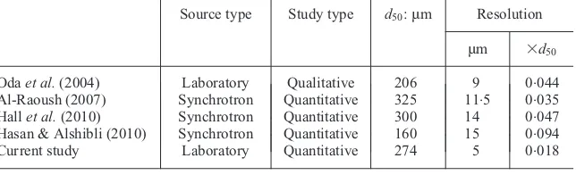
[image:3.595.65.291.428.611.2]As outlined by Stock (2008) or Ketcham & Carlson (2001), when using CT the image field of view (FOV) should be larger than the object, and the smaller the FOV the smaller the voxel size. The voxel size used in this research was 5ìm, after a 23232 binning (i.e. a volume of 23voxels was replaced by 1 voxel) to cope with computer memory issues. This voxel size is almost an order of magnitude greater than that achieved in key earlier geotech-nical studies (Table 1), noting that the resolution is related to the cube of the voxel length. When using micro-CT data to characterise the internal structure of a material, the image quality and voxel size required are both functions of the size of the features of interest that need to be resolved, and of the purpose of the current investigation. When the contact, particle and void morphologies are all considered, as in the current investigation, small voxel sizes are required to achieve the desired resolution of all these features. Thus the sample size, voxel size and scanning parameters are based on a compromise between three main factors: image quality, time taken and cost of the process.
Table 2 summarises the 13 mini-cores scanned for eight intact (Int-1-a to Int-4-b-S) and five reconstituted (Rec-1-a to Rec-4-S) samples. As shown in Table 2, the load stages at which micro-CT scans were performed corresponded to dif-ferent strains for the intact and reconstituted samples. For the intact soil, two samples were cored from the shear band region at load stages 3 and 4 (samples Int-3-b-S and Int-4-b-S respectively), but, since the mini-cores are larger than the shear band thickness, each sample is composed of particles from both inside and outside the shear band. For the recon-stituted soil, one sample intercepted the shear band at load stage 4 (Rec-4-S). All the remaining samples were either taken before the shear band developed or do not contain a significant part of the shear band region.
All of the data presented were acquired in one of two nanotom micro-CT scanners, developed by phoenix|X-ray (GE). Full details of the systems used and the scanning parameters are given by Fonseca (2011). Images obtained using laboratory micro-CT scanners can exhibit artefacts and 2000
1600
1200
800
400
0
σσ13
: kP
a
⫺
0 5 10 15
εa: %
Dev. stress intact Dev. stress recon. Vol. strain intact Vol. strain recon.
⫺20
⫺15
⫺10
⫺5
0
5
εv
: %
[image:3.595.146.468.681.779.2]Fig. 2. Mechanical response
Table 1. Comparison of spatial resolution and source type used in selected recent studies using high-resolution tomographic images of sand
Source type Study type d50:ìm Resolution ìm 3d50
Odaet al.(2004) Laboratory Qualitative 206 9 0.044
Al-Raoush (2007) Synchrotron Quantitative 325 11.5 0.035
Hallet al.(2010) Synchrotron Quantitative 300 14 0.047
other shortcomings (e.g. Davis & Elliott, 2006), complicat-ing subsequent image analysis. Synchrotron radiation images can potentially have higher quality, as a monochromatic X-ray beam can be used, there is a higher photon flux, and the signal-to-noise ratio is better (Stock, 2008). Access to synchrotron radiation sources is limited, and although there are examples of use of synchrotron facilities in geomech-anics studies (as noted in Table 1), laboratory sources are more common, and are likely to continue to be adopted in geomechanics research.
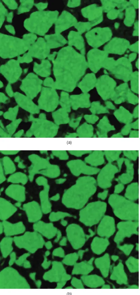
Careful consideration had to be given to particles that intercepted the scan boundary, and the number of complete ‘inner’ particles that did not touch the boundaries is indi-cated in Table 2. Per-particle statistics (e.g. coordination number) were then calculated only for the inner particles, as detailed in Fonseca (2011). Figs 3(a) and 3(b) illustrate small sections through tomographic data for an intact and a reconstituted specimen of Reigate sand respectively.
VOID RATIO
The void ratios calculated from the micro-CT data (eCT) were compared with the overall void ratios measured in the laboratory (elab) to assess the reliability of the micro-CT results. The elab measurements for load stage 1 were based on the initial weight and volume of the triaxial specimen (for a density of 2648 Mg/m3), and during deformation the change of volume was calculated from local measurements of axial and radial strains using linear variable differential transducers (LVDTs). The output from a micro-CT scan is a dataset of voxels, and the voxel colour intensity is a measure of the X-ray attenuation at that point in the sample. Ideally, the solid and void phases in the samples should be easily differentiated, because the differences in density and atomic number give marked differences in attenuation. Noise and artefacts present in micro-CT data complicate the differentia-tion of the two phases. The data were first enhanced using a 33333 median filter, and then a threshold was used to select the attenuation intensity to differentiate the solid particle phase from the resin-filled void phase. The threshold value was defined by fitting Gaussian curves to each of the two peaks of the intensity histogram, and finding the mini-mum point between them. The eCT measurements are very sensitive to the threshold value selected, and for this reason the initial threshold value was verified using the method proposed by Otsu (1979), which divides the histogram into two classes, and minimises the intra-class variance between (algorithm implemented in ImageJ; Schneider et al., 2012). While the threshold has a large influence on both the e
measurements and contact analysis, much of the
uncertain-Table 2. Sample conditions and key values
Sample Load stage details åa: % q/p9 e Total no. of
particles
No. of inner particles
No. voxels per particle (average)
Int-1-a Prior to iso comp – – 0.48 2329 1438 74 059 Int-1-b Prior to iso comp – – 0.48 4078 2849 138 600 Int-2-a Onset of dilation 0.37 1.96 0.46 3004 1930 55 936 Int-2-b Onset of dilation 0.37 1.96 0.46 2633 1635 66 254 Int-3-a Start of visible shear band 3.89 1.73 0.63 3959 2574 40 513 Int-3-b-S Start of visible shear band 3.89 1.73 0.63 3082 1912 47 200 Int-4-a Approaching critical state 7.94 1.38 0.67 2618 1598 61 486 Int-4-b-S Approaching critical state 7.94 1.38 0.67 5324 3247 104 570 Rec-1-a Prior to iso comp – – 0.50 3845 2513 39 893 Rec-1-b Prior to iso comp – – 0.50 3385 2110 169 740 Rec-3-a Start of visible shear band 9.66 1.46 0.87 4142 2704 35 977 Rec-3-b Start of visible shear band 9.66 1.46 0.87 4907 3387 27 504 Rec-4-S Approaching critical state 12.35 1.46 0.70 3906 2591 35 070
(a)
[image:4.595.41.537.70.235.2](b)
[image:4.595.302.531.265.748.2]ties commonly associated with the threshold value selection can be reduced by using sharp images where the grain boundaries can be more easily defined. The thresholding segmentation generated a three-dimensional binary image, so that each voxel was identified as being either void space (with a colour or intensity of 0) or solid particle (with a colour or intensity of 1), and the void ratio (eCT) was calculated as
eCT¼
Ntotal voxelN
solid particle voxel
Nsolid particlevoxel (1)
whereNtotal
voxel is the total number of voxels,N
solid particle
voxel is the
number of voxels occupied by solid soil particles.
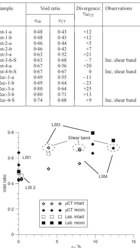
Table 3 and Fig. 4 compare overall (elab) values derived from the dry density of the samples with the eCT values for load stages 1 to 4 (LSt1–LSt4). The normalised differences between the laboratory and micro-CT measurements of void ratio were between9% and +25%. In general,elab is higher thaneCT:These differences can be explained by recognising that the elab values are global, and so do not capture the local variations of void ratio within the specimen. Local void ratio variations are related to both the initial (inherent)
heterogeneity of the material and localisations that form during loading. The eCT values prior to loading for both samples provide evidence of inherent heterogeneity. Whereas the two intact samples have very similar eCT values, theeCT values for the two reconstituted samples differ. These differ-ences can be attributed to the heterogeneity of the reconsti-tuted samples when compared with the intact samples, as was observed in preliminary low-resolution scans (with a voxel size of 45ìm) along the full height of the triaxial sample. This analysis found a slightly uneven distribution of darker voxels (representing the void space) of the reconsti-tuted material, as a result of the specimen preparation process, but no consistent macrostructure was identified (e.g. layering). Once a shear band develops, the volumetric strain estimates made using the LVDT data are less accurate. Here, once a visible shear band has emerged (at strain levels of 3.8% and 9.7% for the intact and reconstituted samples respectively), the reconstituted specimen shows a higher elab value.
For the intact material, at load stages 3 and 4 (axial strains of 3.9% and 7.9%), the two eCT values for samples Int-3-a and Int-4-a both consider the material outside the shear band, and, as expected, these have lower void ratios than samples Int-3-b-S and Int-4-b-S, which consider material that in-cludes the shear band. The eCT values from micro-CT data given in Fig. 4 are from a number of subsamples and so they do not necessarily agree exactly with the changes of e that might be expected from the overall volumetric strains meas-ured for one overall laboratory sample as presented in Fig. 2. The very high difference between elab and eCT (25%) observed for the reconstituted sample Rec-3-a can be attrib-uted to the significant barrelling of the sample at load stage 3, which led to an overestimation of the elab (as a conse-quence of the use of the right cylinder assumption for the cross-sectional area calculation), and also to the sample heterogeneity, which was larger in the reconstituted samples. The good agreement for samples Int-3-b-S and Int-4-b-S is probably to some extent fortuitous. For these samples, which contain the shear band, the eCT values represent some sort of average between the shear band in the middle of the mini-core sample and the soil outside it, but the proportions of soil inside and outside the shear band in this mini-core are very different from those contributing to the global measure-ment,elab, and cannot be easily estimated. For both the intact and reconstituted material, similar void ratios were obtained for the three samples containing the shear band. Whereas for the intact soil it is clear that a limit void ratio is reached in the shear zone, as suggested by Desrues et al. (1996), for the reconstituted soil the inaccuracies of the global measure-ments (as stated previously) may prevent this from being observed.
CONTACT IDENTIFICATION
During the thresholding phase outlined above, the solid particles were separated from the void space; then, to identify contacts, a watershed segmentation process was used to identify individual grains. Here the watershed segmenta-tion algorithm proposed by Beucher & Lantuejoul (1979) was applied using an in-house code (Atwood et al., 2004; Yue et al., 2011), as detailed by Fonseca (2011). This segmentation process assigned an integer identification num-ber to each particle-phase voxel, and each particle was defined as a cloud of voxels that share the same common and unique intensity value.
[image:5.595.61.294.327.739.2]The process of contact identification differs from particle identification, as a contact is not a physical feature of the soil. Considering two contacting particles, with intensity values m1 and m2, the particle m1 voxels were classified as
Table 3. Void ratio measurements
Sample Void ratio Divergence: %eCT
Observations
elab eCT
Int-1-a 0.48 0.43 +12 Int-1-b 0.48 0.43 +12 Int-2-a 0.46 0.44 +5 Int-2-b 0.46 0.43 +7 Int-3-a 0.63 0.52 +21
Int-3-b-S 0.63 0.68 7 Inc. shear band Int-4-a 0.67 0.56 +20
Int-4-b-S 0.67 0.67 0 Inc. shear band Rec-1-a 0.49 0.55 11
Rec-1-b 0.49 0.64 23 Rec-3-a 0.80 0.64 +25 Rec-3-b 0.80 0.71 +13
Rec-4-S 0.74 0.68 +9 Inc. shear band
0 0·2 0·4 0·6 0·8
0 5 10 15
V
oid r
a
tio
εa: % μCT intact
μCT recon. Lab. intact Lab. recon. LSt 2
LSt1
LSt3
LSt4 Shear band
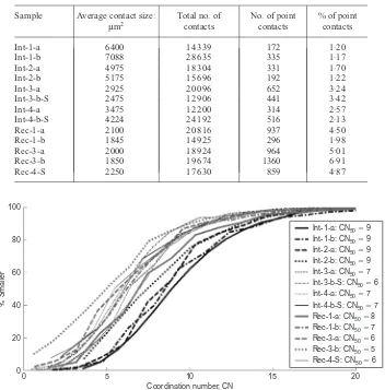
contact voxels if they connected to a voxel of value m2, wherem26¼m1 and m26¼0 (as the void space has intensity 0). The voxel contact classification used in this study was based on a 6-connectivity voxel neighbourhood relation, and required a total of six orthogonal ‘passes’ through the data along the x, y and z directions, as discussed by Fonseca (2011). Table 4 presents the statistics for the contacts identified, including the number of contacts and average contact size for all the samples.
COORDINATION NUMBER
The coordination number (CN) is a measure of the pack-ing density, based on the average number of contacts per particle: that is
CN¼2Nc
Np
(2)
where Np is the number of particles, and Nc is the number of contacts. DEM studies such as Thornton (2000) and Shire & O’Sullivan (2013) have examined the correlation between CN and material response, but there have been only a few experimental studies considering CN – for example the contribution by Oda (1977), who considered glass ballotini. More recently, using micro-CT data, Hasan & Alshibli (2010) measured the coordination number for a resin-impregnated sample of silica sand that included a shear
band; their analysis also considered the relationship between
e and CN.
[image:6.595.115.467.400.757.2]Figure 5 shows the coordination number distribution (CND) for all samples, and Table 5 gives the average CN values (CNave). The curves for the intact samples at load stages 1 and 2 (Int-1-a, Int-1-b, Int-2-a and Int-2-b) are located slightly to the right, with higher CN values than those for the reconstituted samples (1-a, 1-b, Rec-3-a, Rec-3-b and Rec-4-S). Considering the intact material, there is a systematic variation in CND during shearing. Very
Table 4. Contact type details for intact and reconstituted samples
Sample Average contact size:
ìm2 Total no. ofcontacts No. of pointcontacts % of pointcontacts
Int-1-a 6400 14 339 172 1.20
Int-1-b 7088 28 635 335 1.17
Int-2-a 4975 18 304 331 1.70
Int-2-b 5175 15 696 192 1.22
Int-3-a 2925 20 096 652 3.24
Int-3-b-S 2475 12 906 441 3.42
Int-4-a 3475 12 200 314 2.57
Int-4-b-S 4224 24 192 516 2.13
Rec-1-a 2100 20 816 937 4.50
Rec-1-b 1845 14 925 296 1.98
Rec-3-a 2000 18 924 964 5.01
Rec-3-b 1850 19 674 1360 6.91
Rec-4-S 2250 17 630 859 4.87
0 20 40 60 80 100
0 5 10 15 20
% Smaller
Coordination number, CN
Int-1-a: CN50⫽9 Int-1-b: CN50⫽9 Int-2-a: CN50⫽9 Int-2-b: CN50⫽9 Int-3-a: CN50⫽7 Int-3-b-S: CN50⫽6 Int-4-a: CN50⫽7 Int-4-b-S: CN50⫽7 Rec-1-a: CN50⫽8 Rec-1-b: CN50⫽7 Rec-3-a: CN50⫽6 Rec-3-b: CN50⫽5 Rec-4-S: CN50⫽6
Fig. 5. Distributions of CN values
Table 5. Numbers of particles with no contacts (Nc0), one contact
(Nc1), average coordination number (CNave) and mechanical
coordination number
Sample Nc0 Nc1 CNave CNm
similar CNDs were observed for the two intact samples at load stage 1 (Int-1-a and Int-1-b), both samples having the same median value, CN50, of 9, and average values CNave¼9.97 and 10.06. The intact sample CND values for load stage 2 (Int-2-a and Int-2-b) are slightly lower, with a CN50 again of 9 but CNave¼9.52 and 9.60. At these initial stages few particles have CN values higher than 20. The average CN reduces as the shearing progresses, with the intact samples at load stage 3 (Int-3-a and Int-3-b-S) show-ing values of CN50 of 7 and 6 and CNave¼7.81 and 6.75, the lower CN50 and CNave values being associated with the sample that includes part of the shear band (Int-3-b-S). The samples at load stage 4 have CNave of 7.66 and 7.51 for Int-4-a and Int-4-b-S respectively. For load stages 3 and 4, CN values greater than 15 are rare. The reconstituted samples prior to loading (Rec-1-a and Rec-1-b) have CNave of 8.31 and 7.21, and the samples at load stage 3 (Rec-3-a and Rec-3-b) have values of 7.00 and 5.81. At load stage 4 (Rec-4) the average CN is 7.00. For the reconstituted samples in general, CN values greater than 15 were again observed only for a very small number of particles.
When compared with the intact soil, the reconstituted specimens have higher frequencies, associated with lower CN values. It is believed that the resin impregnation process caused some particles with low CN values to float, so reducing their CN still further. Referring to Table 5, there is clearly a greater number of floating or rattler particles (i.e. particles with no contacts or only one contact) in the reconstituted material. There are also significantly more of these types of contact in samples intercepting the shear band (samples Int-3-b-S and Int-4-b-S). On the whole, only a small number of particles have one or no contacts (,4%), and so the average coordination number and the mechanical coordination number are similar for each sample.
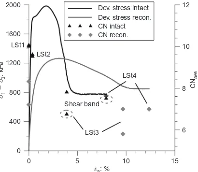
Figure 6 compares the evolution of CNave with the speci-men load–deformation response, and the CN values are compared with the shear stiffness (G) in Fig. 7. G was calculated by taking tangents to the deviatoric stress shear strain curve, where the shear strain was calculated as
ås¼2(åaår)/3, and åa andår are the local axial and radial strains measured with the LVDTs. The systematic decrease in the average CN up to load stage 3 associated with dilation of the material is more notable for the intact material. The higher strength and stiffness values associated with the intact material can qualitatively be linked to the differences in CN, even if the major drop in stiffness for the intact soil actually occurs before the CN changes significantly. Comparing load stages 3 and 4, no significant changes can be observed,
which may be an indication that a critical CN was reached, as observed in previous studies (e.g. Thornton, 2000). It is also interesting that the final CN values for the intact and reconstituted soil are quite similar. For the same load stage, the differences of individual CN values (e.g. intact material load stage 3 and reconstituted material load stages 1 and 3) can partly be explained by the differences in the void ratio between the samples.
The correlation between CNave andeCTfor all the samples is examined in Fig. 8. The trend observed indicates an increase in the number of contacts as the void ratio de-creases, and, considering the entire dataset, the two param-eters may be related by eCT¼1.69exp(0.14CN). For a
dense, reconstituted silica sand, Hasan & Alshibli (2010) reported a similar trend. It is encouraging that the two sets of data are qualitatively similar. There are quantitative differences, however: Hassan & Alshibli found e and CN to be related as e¼2.23exp(0.13CN): that is, they observed a higher value of CN for a given e. This difference may be attributed to differences in particle size distribution, particle morphology, fabric and mode of shearing, as Hasan & Alshibli considered plane-strain compression rather than triaxial compression. Moreover, the voxel size used by Hasan
0 400 800 1200 1600 2000
6 8 10 12
0 5 10 15
σ13
: kP
a
⫺
σ
εa: %
CN
av
e
LSt1 LSt2
LSt4
LSt3 Shear band
[image:7.595.318.550.53.241.2]Dev. stress intact Dev. stress recon. CN intact CN recon.
Fig. 6. Comparison of evolution of coordination number (CNave)
with deviatoric stress response during shearing
0 100 200 300 400 500
6 8 10 12
0·001 0·01 0·1 1 10 100
G
: MP
a
εa: %
CN
av
e
Gintact Grecon. CN intact CN recon.
LSt1
LSt2
LSt4
LSt3 Shear band
Fig. 7. Comparison of evolution of coordination number (CN) with shear modulus (G) response during shearing
0·2 0·4 0·6 0·8 1·0 1·2
5 6 7 8 9 10 11
V
oid r
a
tio
,
eCT
CNave
CN intact
CN recon.
e⫽2·23exp⫺0·13CN
e⫽1·69exp⫺0·14CN
Shear band
(Hasan & Alshibli, 2010)
LSt4
LSt3
[image:7.595.324.541.540.752.2]LSt2 LSt1
Fig. 8. Relation between void ratio (eCT) and coordination
[image:7.595.76.281.571.749.2]& Alshibli was 0.094d50: that is, their images were less detailed, compared with the voxel size of 0.019d50 used in this project. In micro-CT analysis of granular materials, a large voxel size may lead to an overestimation of the num-ber of contacts. Good agreement was found with the meas-urements reported by Oda (1977) for near-spherical ballotini. As expected CN, increases with particle volume, and in both cases and the relationship between CN and the volume was found to be generally quadratic.
CONTACT INDEX
When calculating the coordination number, contacts with a larger area are given the same weight as point contacts. Earlier two-dimensional observations using resin-impregnated Reigate sand (e.g. Richards & Barton, 1999; Cresswell & Powrie, 2004) revealed that this sand typically includes more straight than tangential contacts; there is a relatively high frequency of interpenetrative contacts, plus occasional occur-rences of sutured contacts. These observations motivated an examination of the contact areas. The surface area of each contact (Sc) was calculated by multiplying the number of voxels defining each contact by the area of each voxel (voxel width2) to give the result in ìm2: These data were used to calculate the contact index, which is defined as
CI¼ 1
Np
XNp
i¼1 1
Sp;i
XNc,i
j¼1
Sc;j (3)
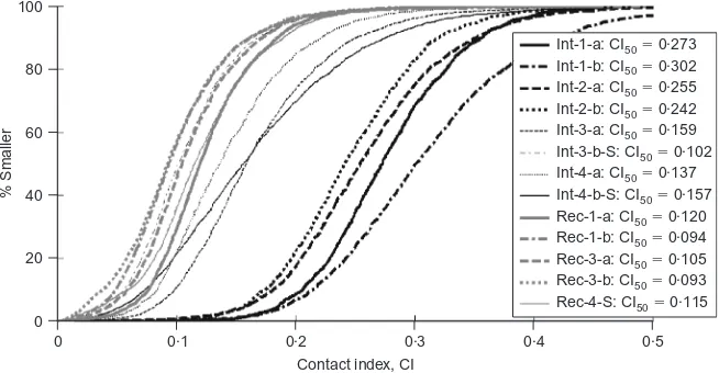
whereNP is the number of particles in the assembly, Sp;i is the surface area of particle i, Sc;j is the surface area of contact j, and Nc,i is the number of contacts involving particle i. Fig. 9 shows the contact index distribution (CID) for all the samples. In comparison with the CNDs illustrated in Fig. 5, the CID curves show a much clearer distinction between the intact samples (Int-1-a and Int-1-b) and the reconstituted samples (Rec-1-a and Rec-1-b) prior to loading, as would be expected from the geological origin of the locked fabric. This clear differentiation between the CI values for the intact and the reconstituted samples prior to the onset of dilation confirms the ability of CI to differenti-ate between the intact locked fabric and the fabric produced in the laboratory. The intact samples at load stage 1 have very high median CI values (CI50), approaching 0.3, indi-cating that on average approximately one third of each particle is ‘covered’ with contact surfaces. The values of CI greater than 0.5 observed for some particles in sample Int-1-b seem rather unrealistic, and are likely to Int-1-be related to the
inherent difficulties in dealing with complex, interlocked contacts. This affects only the intact samples at load stages 1 and 2. At load stage 2 the two intact samples (Int-2-a and Int-2-b) also show high average CI50 values, of around 0.25. The effect of dilation can be observed for sample Int-3-a, where there is a drop in the CI50 value at load stage 3 to a value of approximately 0.16 for the sample located outside the shear band. This reduction in CI as the shearing pro-gresses is believed to be associated with the formation of new contacts with smaller contact areas, and the breaking of the original contacts as a consequence of disruption to the soil fabric. The curves for the intact soil at load stages 3 and 4 (in particular, the sample intercepting the shear band, Int-3-b-S) are located in the same region (with lower CI values) as the reconstituted samples at the same load stage (samples Rec-3-a and Rec-3-b, both of which partially intersect the shear band).
At load stage 4 the intact samples had CI50 values of 0.14 and 0.16. The samples that include the shear band at load stages 3 and 4 show higher CI values than the samples outside the shear band. This was also observed by Wong (2003) in his study of shear bands in an oil sand (with a similar interlocked fabric). Wong (2003) suggested that some original contacts were still preserved inside the shear band, which implies that some sand grains translate and rotate in interlocked groups, instead of moving as individual grains. This difference in particle-scale response and the evolution of CI with strain were not observed for the reconstituted sands. For the reconstituted material the maximum CI values rarely exceed a value of 0.2, the average is approximately 0.1, and there is no clear evolu-tion.
Figure 10 compares the evolution of the average CI values with the load–deformation response for both types of speci-men. There is no significant change in CI for the reconsti-tuted soil, whereas for the intact soil CI clearly decreases with shearing deformation up to load stage 3. As was the case for the CN data, the CI values do not change signifi-cantly during the last stage of shearing. In Fig. 11 the evolution of CI is compared with the degradation of stiff-ness. As for the CN data, it is interesting that, whereas for the intact sample there is an apparent correlation between reducing CI and reducing stiffness, the major degradation of stiffness actually occurs slightly before the more dramatic change in CI. This indicates that Gis sensitive to very small changes in contact conditions, some of which may occur below the image resolution. For the reconstituted sample, unlike CN, where there is a substantial reduction, for CI
0 20 40 60 80 100
0 0·1 0·2 0·3 0·4 0·5
% Smaller
Contact index, CI
[image:8.595.127.454.587.757.2]Int-1-a: CI50⫽0·273 Int-1-b: CI50⫽0·302 Int-2-a: CI50⫽0·255 Int-2-b: CI50⫽0·242 Int-3-a: CI50⫽0·159 Int-3-b-S: CI50⫽0·102 Int-4-a: CI50⫽0·137 Int-4-b-S: CI50⫽0·157 Rec-1-a: CI50⫽0·120 Rec-1-b: CI50⫽0·094 Rec-3-a: CI50⫽0·105 Rec-3-b: CI50⫽0·093 Rec-4-S: CI50⫽0·115
there is no change, indicating that the new contacts made during shearing are of similar morphology to those created during sample preparation.
The relationship between CIave and eCT is plotted in Fig. 12(a) for both materials. Clearly, there is a much stronger correlation between the void ratio and the CI values for the intact material, the CIave values clearly reducing as the material dilates. In the absence of a locked fabric in the reconstituted material, there is less variation in CI, and this parameter does not change with eCT, as might be expected through changes to the number of contacts. Fig. 12(b) compares the CIave and CNave values, and again the CIave values for the reconstituted soil are relatively insensi-tive to the change in density picked up by the CNave values. It should be emphasised that the relationships shown on these two figures are valid only for this particular test (i.e. a drained triaxial test at 300 kPa), and are not general. The void ratio changes would depend critically on the stress level, but the reduction of CI with increasing shear strain would be expected no matter what stress level was used. These data do, however, suggest that the CI values can give an indication of damage (i.e. the destruction of the locked fabric, which is due largely to shear strain), but that CI does
0 400 800 1200 1600 2000
0 0·1 0·2 0·3 0·4
0 5 10 15
σσ13
: kP
a
⫺
εa: %
CI
av
e
Dev. stress intact Dev. stress recon. CI intact CI recon.
LSt2 LSt1
LSt4
[image:9.595.68.291.52.241.2]LSt3 Shear band
Fig. 10. Comparison of evolution of contact index (CIave) with
deviatoric stress response during shearing
0 100 200 300 400 500
0 0·1 0·2 0·3 0·4
0·001 0·01 0·1 1 10 100
G
: MP
a
εa: %
CI
av
e
Gintact Grecon. CI intact CI recon.
Shear band
LSt4
LSt3 LSt1
[image:9.595.318.548.52.540.2]LSt2
Fig. 11. Comparison of evolution of contact index (CIave) with
shear modulus (G) during shearing
0·4 0·5 0·6 0·7 0·8
0 0·1 0·2 0·3 0·4
V
oid r
a
tio
,
eCT
CI (a)
ave
Intact
Intact
Recon.
Recon. Shear band
LSt3
LSt3 LSt1
LSt1 LSt2
LSt4
5 6 7 8 9 10 11
0 0·1 0·2 0·3 0·4
CN
av
e
CI (b)
ave
LSt1
LSt3
Shear band LSt4
LSt3 LSt2
LSt1
Fig. 12. (a) Relationship between void ratio (eCT) and contact
index (CIave); (b) relationship between CNaveand CIave
0 0·1 0·2 0·3 0·4 0·5
0 5 10 15 20 25 30
CI
CN
[image:9.595.65.289.299.474.2] [image:9.595.327.543.592.752.2]not effectively pick up fabric changes due to volumetric strain (dilation in this case).
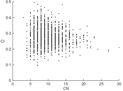
The relationship between CN and CI for individual parti-cles was investigated, and Fig. 13 compares the initial CN and CI values at load stage 1 for particles in a representative intact sample. The plot shows significant scatter, and no clear trends can be observed. Similar observations were made when considering the reconstituted material. Low CN values are associated with a wide range of CI values, and as CN increases this range of CI values reduces, and tends to stabilise at around the mean CI value.
It is not surprising that little correlation can be observed between CN and CI, given that the indices measure very different characteristics. An increase in the number of contacts may indicate a denser packing, but point-like contacts will not contribute much to an increase of the CI values. In fact, a high number of contacts per particle may limit the possible surface area of each contact. Note also that, in contrast to the CN values, no correlation was ob-served between CI and particle volume.
In his analysis of two-dimensional images of locked sands, Barton (1993) classified contacts as being tangential, straight, concavo-convex, non-continuous or sutured. Quan-titative application of this scheme in three dimensions is non-trivial, and so a simpler classification was adopted here. Contacts were considered to be point contacts if they were defined by 6 voxels or less, corresponding to an area of 54 or 150ìm2 depending on the voxel size of the image (i.e. 3 or 5ìm). This was considered to be the minimum viable size for more detailed description of the straight contacts (e.g. contact normal orientation). Using optical microscope images of thin sections of Reigate sand speci-mens, Richards & Barton (1999) reported an average coordination number of 1.8, and 35% of tangential contacts relative to the total number of contacts. The average coordination number measured in this study for the intact samples was 10.0, and the proportion of tangential contacts was 98.8%. The differences in the results may be a consequence of the different techniques and criteria used for contact definition. Nonetheless, it also highlights the limitations of a two-dimensional analysis, in which only the contacts intercepted by the image plane are taken into consideration, and a contact can be erroneously classified as point like when it develops out of the image plane. Referring to Table 4, the percentage of point contacts increases as shearing progresses, and the values are signifi-cantly higher for the reconstituted soil.
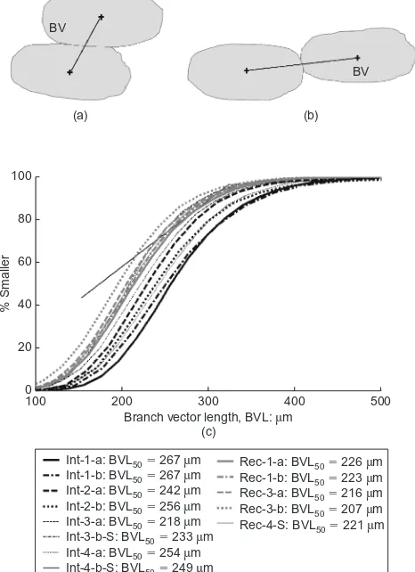
BRANCH VECTOR LENGTH
The branch vector (BV) is the vector joining the centroids of each pair of contacting particles, as illustrated in Figs 14(a) and 14(b). The branch vector length (BVL) can give an indication of how particles form contacts relative to the orientation of the particle major and minor axes. Although the BVL can provide a quantitative descrip-tion of how the packing evolves with shearing, there are two factors that may limit its effectiveness. The first is its dependence on both size and shape of the particles, and the second is the fact that, as the soil dilates, the contacts are lost, and the branch vector can no longer describe the deformation. The cumulative distributions of branch length are given in Fig. 14(c), and the correlation between the mean diameter and the average BVL is presented in Fig. 15(a). Because of some breakage of the soil during recon-stitution and shearing (Fonseca et al., 2012a) the decrease of BVL can be related to reduction of grain size. The general trend of BVL to decrease with deformation can be interpreted as an indication that the contacts that remain are
those formed in a ‘more stable’ manner, as illustrated in Fig. 14(a). Referring to Fig. 15(b), the evolution of the average BVL values and the void ratio (eCT) also highlights the reduction of BVL from stage 1 to stage 3. The different trend observed for stage 4, for both intact and reconstituted materials, can be related to the similar phenomenon ob-served for the evolution of CI, and may again be related to the deformation of the grains in clusters inside the shear band.
VOID SIZE ANALYSIS
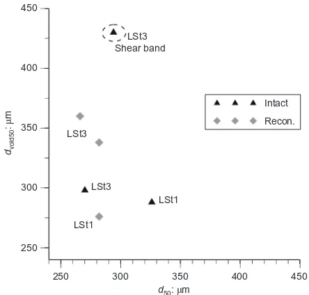
The void sizes were analysed for six of the 13 samples. The identification of individual voids is somewhat ambigu-ous, as all the voids are interconnected in three dimensions, so the watershed algorithm described above was applied to segment the void space. Ghedia & O’Sullivan (2012) also used this approach in two dimensions. Cumulative void size distributions (VSDs) are given in Fig. 16, using the lengths of the intermediate axes of the voids to quantify the size. Initially, the VSDs of both the intact and reconstituted soils are close to the particle size distribution (PSD) measured by sieving, but as shearing continues, the VSDs increase as the soil dilates. To investigate the influence of the PSD on the VSD, the mean particle diameter (d50) is compared with the mean void diameter in Fig. 17. Although, for the initial stage, the intact soil has larger grains than the reconstituted soil, the void sizes are not so significantly different. Simi-larly, the difference in the void sizes between stages 1 and 3 for the intact soil is much smaller than the corresponding
BV
(a)
BV
(b)
0 20 40 60 80 100
100 200 300 400 500
% Smaller
Branch vector length, BVL: m (c)
μ
Int-1-a: BVL50⫽267 mμ Int-1-b: BVL50⫽267 mμ Int-2-a: BVL50⫽242 mμ Int-2-b: BVL50⫽256 mμ Int-3-a: BVL50⫽218 mμ Int-3-b-S: BVL50⫽233 mμ Int-4-a: BVL50⫽254 mμ Int-4-b-S: BVL50⫽249 mμ
Rec-1-a: BVL50⫽226 mμ
[image:10.595.301.534.61.382.2]Rec-1-b: BVL50⫽223 mμ Rec-3-a: BVL50⫽216 mμ Rec-3-b: BVL50⫽207 mμ Rec-4-S: BVL50⫽221 mμ
change in d50:As expected, the sample containing the shear band exhibits larger voids than the sample outside the shear band. The difference is more pronounced for the intact soil, which confirms that the degree of localisation is greater for this material.
CONCLUSIONS
In common with previous work using micro-CT, this paper has shown that examination of the internal structure of sand at the particle scale can provide a rational explanation for macro-scale differences in mechanical response. Although different soil samples were used for each load stage, the initial void ratios and mechanical responses were very similar, and so each sample can be considered to give a representative material response. The advantage of this approach, as compared with imaging during a single test, is that micro-CT or nano-CT may be used, whereas a synchro-tron is often needed for the latter method to achieve an adequate resolution and reasonable sample size. A more sophisticated triaxial apparatus may also be used, for exam-ple with local measurement of strains. The main disadvan-tage is that the development of the fabric of a single sample cannot be traced throughout the loading history, and so there is inevitably some scatter in the data. The compromise between the sample size and the image resolution is a pertinent issue in this area of research. Although some scatter due to the initial heterogeneity of the reconstituted samples could have been reduced by using larger samples, the intact soil had provided consistent results, giving unique insights only possible using high-resolution data.
Comparing the intact and reconstituted samples, signifi-cant differences in the packing density were revealed that cannot be detected by consideration of void ratio alone. The higher strength and stiffness observed for the intact material can be attributed to the greater contact density within the sample. Upon shearing, the initially high values of both coordination number (CN) and contact index (CI) decreased to quasi-stable values, coinciding with the plateau in the stress–strain response. This observation is in accordance with the critical CN observed by Thornton (2000) using DEM simulations. In comparison with CN, CI was found to be more effective to describe the evolution of the contact densities. Moreover, the potential of using CI for fabric description is reinforced by the fact that it is fairly size insensitive. The results have shown that the soil stiffness is sensitive to very small adjustments in the initial packing/ contacts that cannot be described by CN, and were too small to be picked up by the CI values used here; perhaps an even greater resolution of CI would be able to identify them. Neither CI nor CN alone appeared to be able to capture all of the important changes to the contacts during loading; CI 200
220 240 260 280
240 260 280 300 320 340
BVL
: m
av
e
μ
d50: m
(a)
μ
Intact
Intact Recon.
Recon. LSt1
LSt1
LSt2
LSt2 LSt4
LSt4 LSt1
LSt1 LSt4
LSt4 LSt3
LSt3 LSt3
LSt3
Shear band
Shear band
0·4 0·5 0·6 0·7 0·8
200 220 240 260 280
V
oid r
a
tio
,
eCT
BVLave: mμ (b)
Fig. 15. (a) Relationship between particled50and average BVL;
(b) relationship between average BVL and void ratio (eCT)
0 10 20 30 40 50 60 70 80 90 100
% Smaller
Void size: mm
10⫺1 100
Int-1-a:dv50⫽288 mμ
Int-3-a:dv 298 m
50⫽ μ
Int-3-b-S:dv50⫽430 mμ
Rec-1-a:dv50⫽276 mμ
Rec-3-a:dv50⫽338 mμ
Rec-3-a:dv50⫽360 mμ
[image:11.595.71.287.42.481.2]Part siev.dv50⫽274 mμ
Fig. 16. Void size distribution
250 300 350 400 450
250 300 350 400 450
dvoid50
: m
μ
d50: mμ
Intact
Recon. LSt3
Shear band
LSt3
LSt1
[image:11.595.322.544.51.263.2]LSt1 LSt3
Fig. 17. Relationship between the particle d50 and void d50
[image:11.595.60.293.530.676.2]identified damage to contacts through shear-straining the soil, but CN captured better the change of contacts due to the volumetric response.
The data on the evolution of the branch vector length are difficult to interpret, given that the particle size also changes with shearing, owing to particle breakage. However, when applied to a material with no breakage during deformation, the BVL parameter can provide information on the way the contact evolves with deformation. The evolution of the size of the voids has shown that the initial PSD has little influence on the VSD, and the main increase in the size of the voids occurs inside the shear band. The degree of localisation can be related to the size of the voids inside the shear zone; this investigation has indicated that the intact soil shows larger voids inside the shear band when compared with the reconstituted soil.
By applying the new technology of micro-CT to reconsti-tuted and intact samples of a natural sand, this research has aided understanding of the fundamental response of the soil. Fonsecaet al.(2012b) have quantified fabric changes for the same tests using directional parameters such as the orienta-tions of particles, voids, contacts and branch vectors. Direc-tional information of this type should be related to anisotropy in the macroscopic behaviour. In this paper it has been shown that other aspects of behaviour – particularly the dilation, which controls peak strength, and the stiffness – are closely related to scalar measurements of fabric.
ACKNOWLEDGEMENTS
The investigations presented in this paper were carried out under the financial support of a Portuguese government body, Fundac¸a˜o para a Cieˆncia e a Tecnologia, as part of the PhD research of the first author. The authors would also like to express their gratitude to GE Measurement & Control Solutions (Du¨sseldorf, Germany).
NOTATION
BVLave average branch vector length (BVL)
BVL50 median value of BVL
CI50 median value of contact index (CI)
CNave average coordination number (CN)
CN50 median value of CN d50 mean particle diameter
dvoid50 mean void diameter (¼dv50)
e void ratio
eCT void ratio calculated from micro-CT data elab void ratio measured in the laboratory
G shear stiffness
m1, m2 intensity of the voxels defining two particles Nc number of contacts
Nc0 number of particles with no contacts Nc1 number of particles with one contact Nc,i number of contacts involving particlei
Np number of particles
Nsolid particlevoxel number of voxels occupied by solid soil particles
Ntotalvoxel total number of voxels
n porosity
p9 mean normal effective stress (¼(ó1–ó3)=3) q deviatoric stress (¼ó1–ó3)
Sc surface area of contact Sc;j surface area of contactj
Sp;i surface area of particlei v specific volume
åa axial strain
år radial strain
ås shear strain
åv volumetric strain
ó1 axial effective stress
ó3 radial effective stress
REFERENCES
Al-Raoush, R. (2007). Microstructure characterization of granular materials.Physica A377, No. 2, 545–558.
Atwood, R. C., Jones, J. R., Lee, P. D. & Hench, L. L. (2004). Analysis of pore interconnectivity in bioactive glass foams using X-ray microtomography. Scr. Mater. 51, No. 11, 1029– 1033.
Barton, M. E. (1993). Cohesive sands: the natural transition from sands to sandstones. Proc. 1st Int. Symp. Geotech. Engng Hard Soils – Soft Rocks, Athens1, 367–364.
Bhandari, A. (2009).The mechanics of an unbonded locked sand at low effective stresses. PhD thesis, University of Southampton, UK.
Been, K. & Jefferies, M. (1985). A state parameter for sands.
Ge´otechnique 35, No. 2, 99–112, http://dx.doi.org/10.1680/ geot.1985.35.2.99.
Beucher, S. & Lantuejoul, C. (1979).Use of watersheds in contour detection. Rennes, France: CCETT.
Cuccovillo, T. & Coop, M. R. (1997). Yielding and pre-failure deformation of structured sands.Ge´otechnique47, No. 3, 491– 508, http://dx.doi.org/10.1680/geot.1997.47.3.491.
Cuccovillo, T. & Coop, M. R. (1999). On the mechanics of structured sands. Ge´otechnique 49, No. 6, 741–760, http:// dx.doi.org/10.1680/geot.1999.49.6.741.
Cresswell, A. & Powrie, W. (2004). Triaxial tests on an unbonded locked sand. Ge´otechnique 54, No. 2, 107–115, http:// dx.doi.org/10.1680/geot.2004.54.2.107.
Davis, G. & Elliott, J. (2006). Artefacts in X-ray microtomography of materials.Mater. Sci. Technol.22, No. 9, 1011–1018. Desrues, J., Chambon, R., Mokni, M. & Mazerolle, F. (1996). Void
ratio evolution inside shear bands in triaxial sand specimens studies by computed tomography.Ge´otechnique46, No. 3, 529– 546, http://dx.doi.org/10.1680/geot.1996.46.3.529.
Fonseca, J. (2011). The evolution of morphology and fabric of a sand during shearing. PhD thesis, Imperial College London, University of London, UK.
Fonseca, J., O’Sullivan, C., Coop, M. R. & Lee, P. D. (2012a). Non-invasive characterisation of particle morphology of natural sands.Soils Found.52, No. 4, 712–722.
Fonseca, J., O’Sullivan, C., Coop, M. R. & Lee, P. D. (2012b). Quantifying the evolution of soil fabric during shearing using directional parameters. Ge´otechnique http://dx.doi.org/10.1680/ geot.12.P.003.
Ghedia, R. & O’Sullivan, C. (2012). Quantifying void fabric using a scan-line approach.Comput. Geotech.41, April, 1–12. Hall, S., Bornert, M., Desrues, J., Pannier, Y., Lenoir, N., Viggiani,
G. & Be´suelle, P. (2010). Discrete and continuum analysis of localised deformation in sand using X-ray microCT and volu-metric digital image correlation.Ge´otechnique60, No. 5, 315– 322, http://dx.doi.org/10.1680/geot.2010.60.5.315.
Hasan, A. & Alshibli, K. (2010). Experimental assessment of 3D particle-to-particle interaction within sheared sand using synchrotron microtomography. Ge´otechnique 60, No. 5, 369– 379, http://dx.doi.org/10.1680/geot.2010.60.5.369.
Ketcham, R. & Carlson, W. (2001). Acquisition, optimization and interpretation of X-ray computed tomographic imagery: applica-tions to the geosciences.Comput. Geosci.27, No. 2, 381–400. Oda, M. (1977). Co-ordination number and its relation to shear
strength of granular material.Soils Found.17, No. 2, 29–42. Oda, M., Takemura, T. & Takahashi, M. (2004). Microstructure in
shear band observed by microfocus X-ray computed tomography.
Ge´otechnique 54, No. 8, 539–542, http://dx.doi.org/10.1680/ geot.2004.54.8.539.
Otsu, N. (1979). A threshold selection method from gray-level histograms.IEEE Trans. Sys., Man, Cyber.9, No. 1, 62–66. Richards, N. P. & Barton, M. E. (1999). The Folkestone Bed
Sands: microfabric and strength. Q. J. Engng Geol. 32, No. 1, 21–44.
Schneider, C. A., Rasband, W. S. & Eliceiri, K. W. (2012). NIH Image to ImageJ: 25 years of image analysis. Nature Methods
9, No. 7, 671–675.
Shire, T. & O’Sullivan, C. (2013). Micromechanical assessment of an internal stability criterion.Acta Geotech.8, No. 1, 81–90. Sorby, H. (1908). On the application of quantitative methods to the
Stephenson, L. P., Plumley, W. J. & Palciauskas, V. V. (1992). A model for sandstone compaction by grain interpenetration. J. Sediment. Res.62, No. 1, 11–22.
Stock, S. R. (2008). Recent advances in X-ray microtomography applied to materials.Int. Mater. Rev.53, No. 3, 129–181. Thornton, C. (2000). Numerical simulations of deviatoric shear
deformation of granular media.Ge´otechnique50, No. 1, 43–53, http://dx.doi.org/10.1680/geot.2000.50.1.43.
Wong, R. C. K. (2003). Strain-induced anisotropy in fabric and
hydraulic parameters of oil sand in triaxial compression. Can. Geotech. J.40, No. 3, 489–500.
Wroth, C.P. & Bassett, R. H. (1965). A stress–strain relationship for the shearing behaviour of a sand.Ge´otechnique15, No. 1, 32–56, http://dx.doi.org/10.1680/geot.1965.15.1.32.