http://dx.doi.org/10.21622/RESD.2016.02.1.005
6
Comparative Study of Modulation Techniques for
Two-Level Voltage Source Inverters
P Li, G P Adam, Member IEEE, D Holliday and B W Williams University of Strathclyde, Glasgow, United Kingdom.
Abstract - A detailed comparative study of modulation techniques for single and three phase dc-ac inverters is presented. Sinusoidal Pulse Width Modulation, Triplen Sinusoidal Pulse Width Modulation, Space Vector Modulation, Selective Harmonic Elimination and Wavelet Modulation are assessed and compared in terms of maximum fundamental output, harmonic performance, switching losses and operational mode. The presented modulation techniques are applied to single and three phase voltage source inverters and are simulated using SIMULINK. The simulation results clarify the inverter performance achieved using the different modulation techniques.
Keywords - Modulation techniques, two-level voltage source inverter, comparative study, fundamental and harmonics.
I. INTRODUCTION
The most recently proposed modulating strategies are generally for application in complicated cascaded modular inverters, matrix converters or other novel converter configurations [1-4]. However, all these modulation strategies are based on classical theory and techniques, such as Sinusoidal Pulse Width Modulation (SPWM), Space Vector Modulation (SVM) and Selective Harmonic Elimination (SHE).
Wavelet modulation (WM) theory has been proposed [5, 6], in which it is claimed that wavelet based PWM has advantages over traditional modulation strategies, specifically SPWM, SVM and SHE. Some of the claimed advantages are [5]: extension of the modulation index linear range beyond that possible with SHE and SVM, and five-level line-to-line voltage waveform, hence low harmonic content and dv/dt. Tri-state leg output voltages are assumed from a two-level voltage source inverter with an inductive load [5], yet this condition can only be created with PWM current source inverters. The implication of such a
tri-state condition is that a large capacitive output filter must be connected to ensure that load current is continuous. In addition, the new wavelet PWM technique is not suitable for variable speed drive applications since the modulation index can only vary within a narrow range, which is limited by the switching frequency. In an attempt to clarify some of the claims relating to WM [5, 6], this paper presents a detailed comparison between wavelet based and traditional PWM strategies. The comparison considers maximum attainable fundamental output voltage, harmonic performance based on weighted total harmonic distortion (wTHD), switching frequency per device and operational mode. The comparison uses wTHD rather than THD since it better reflects the individual voltage harmonics in the load current.
II. REVIEW OF INVERTER VOLTAGE MODULATION TECHNIQUES
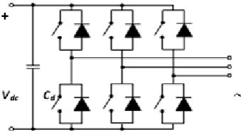
[image:1.596.337.507.616.713.2]Two-level voltage-source-converter modulation techniques have been intensively researched. In principle, all modulation methods aim to lower harmonic distortion in the output voltage and current, improve dc link utilization, and minimize switching losses, among which there is a trade-off in order to achieve balanced inverter performance under all operating conditions. The three-phase bridge converter in Fig.1 is widely employed in low and medium voltage applications.
Fig .1. Three-phase voltage source inverter
7
signal over one switching or fundamental period. Its disadvantages are that the maximum linear modulation index is limited to 1pu (4/π being that for a square-wave fundamental) and that the switching devices experience the full carrier frequency. Third harmonic (or triplen) injection SPWM (TSPWM) extends the maximum modulation index to 1.155pu, but inherent are all the other features of SPWM as well as the introduced zero-sequence components in the phase voltages that do not contribute to the three-phase load currents. SVM is developed from the space vector representation of the inverter output voltage in the α-β plane. DC voltage utilization is 1.155pu. The technique offers additional flexibility in terms of pulse placement and switching pattern selection, hence switching losses can be optimized. SVM is suitable for real-time and digital implementation. SHE controls the fundamental voltage and eliminates specific harmonics by directly calculating the switching instants. In this manner, SHE can generate high quality output voltage at a lower switching frequency when compared to other methods, and a relatively high modulation index is achievable in three-phase systems.
The WM method defines the linearly combined scaling function (1) to generate a train of rectangular pulses with various widths and shifts.
1 1 ( 1)
( )
(2
j)
(2
j(
1 2
j))
j
t
Ht
Ht
(1)
where scale j is defined as
j=1, 2, 3, … and
φ
His the Haar-scaling function [5]. The scale-base linearly combined synthesis scaling function at scale j is defined by (2) [5].( )
( )
( )
j
t
Ht
jt
(2)
Fig.2. illustrates the generation of WM modulation gating signals using (1) and (2).
(a) switching instants calculated by defined scaling function (1)
(b) synthesis scaling function for gate signals defined in (2)
Fig .2Basic functions in wavelet modulation theory Reference [5] shows that the three-phase inverter output line voltage has five voltage levels, which means that the phase voltage must be 3-level. This is not achievable with an inductive load.
In open-loop applications, WM can be implemented on-line since, advantageously, the real-time calculations are linear and can be solved by a processor without significant delay.
The switching frequency fsw with the WM method is determined by the maximum scale value J, as shown in (3) where f0 is the fundamental frequency, and where quarter-wave and half-wave symmetrical output waveforms can be obtained. The output voltage contains no even order harmonics.
(4
1)
sw o
f
J
f
(3)
The modulation index, related to half of the dc bus
voltage, V
dc,
for WM, can be determined by Error! Reference source not found. whereV
p1is the peak line-to-line fundamental voltage,j = 1, 2… J and
(t
j1, t
j2) = (j+2
-(j+1), j+1-2
-(j+1))
are the switching instants on a normalized time axis used to define the new scale-based linearly-combined scaling function.1 1
1 1 2
1
1 2
4
(2 cos( ) 1 2 (cos( ) cos( )))
J p
a J j j
dc j
V
m t t t
V
(4)
where
2J 1
.
[image:2.596.306.549.64.136.2] [image:2.596.55.289.615.684.2]http://dx.doi.org/10.21622/RESD.2016.02.1.005
8
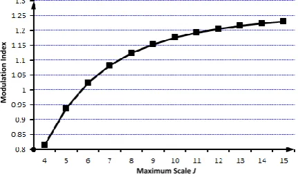
Fig.3 plots the theoretical variation of modulation index with J. It can be concluded that the modulation index limit for WM is 1.273 (4/π): the same as with square wave inversion. The available modulation index range is, however, limited to 0.95-1.15, corresponding to J varying discretely between 5-10. If J exceeds this recommended range, low-order voltage harmonics are observed to increase rapidly, where these harmonics exhibit fixed leading or lagging phase shifts with respect to the fundamental.
Maximum Scale J
M
o
d
u
la
ti
o
n
In
d
e
x
Fig .3Theoretical modulation index versus maximum scale J for WM
III. COMPARATIVE STUDY OF MODULATION METHODS
In this comparison, the inverter of Fig.1 with
V
dc=100V and f
0=60Hz,
as detailed in Table I, is the basis for the simulation study. Five modulation techniques: SPWM, TSPWM, SVM, SHE and WM are analyzed.The dc voltage utilization coefficient
λ,
defined by Error! Reference source not found., specifies the voltage transfer limit and is inherently restricted to 1.1 for a square wave mode.dc p
V
V
λ=
1(5)
Harmonic performance is usually evaluated using THD. Since low-order harmonics contribute the most significant current components to the load, wTHD is used in this case to determine the effective harmonic content of the output voltage waveform. The method for calculating wTHD is shown in (6), with an upper limit of the 75th harmonic being specified for this comparative study.
1 2
2
p n
np
V n V
wTHD
(6)
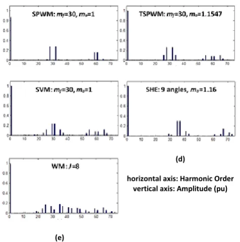
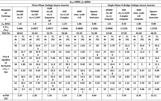
Fig.4 shows the output voltage waveforms for the wavelet modulated VSI. For different modulation methods at maximum linear output, the various positions and widths in the rectangular pulses contribute to the different spectra, as indicated in Fig.5. The dc bus voltage is the base used to normalize the spectral component magnitudes, thereby allowing performance comparison between each modulation method. The detailed and quantitative results for the output fundamental and harmonic component amplitudes are shown in Table I. For each of the five modulation techniques investigated, the table also shows dc voltage utilization, the amplitudes of the first eight significant harmonics expressed as a percentage of the fundamental and the WTHD.
A. SPWM:
Fig.5 (a) shows the spectrum of output line-to-line voltage for SPWM and that all of the significant harmonics are concentrated around the sidebands of the switching frequency components. The maximum dc voltage utilization is 86.6% and WTHD is 1.57%, as shown in Table I.
B. TSPWM:
As shown in Fig.5 (b) and Table I, injection of the 3rd harmonic into the modulating wave extends the linear modulation index to 115.5% of that of SPWM and that the output 3rd harmonics in each phase are cancelled by the three-phase configuration. The wTHD is decreased to 1.36% due to the increased fundamental component.
[image:3.596.61.277.232.360.2] [image:3.596.310.557.610.684.2]
9
(d)
horizontal axis: Harmonic Order vertical axis: Amplitude (pu)
SVM generates waveforms with a similar maximum fundamental output to TSPWM, as shown in Fig.5 (c) and Table I. The corresponding WTHD is 1.35%. However, there will be deviation from the ideal situation as the sidebands around the first switching frequency manifest as low order harmonics.
(e)
Fig 5.Line-to-line voltage spectra for different modulation methods (peak value normalized to Vdc) versus Harmonic order
D. SHE:
The WTHD under SHE modulation with an equivalent switching frequency of 19 times the fundamental (which is lower than for the other methods) is 1.24%, and the first significant harmonics are the
29
thand
31
st, as
shown in Error! Reference source not found. I and Fig.5 (d). By design, the low-order harmonic amplitudes are all close to zero and the fundamental peak is slightly higher than those for SVM and TSPWM. By constraining the maximum linear modulation index to 1.16, nine controllable switching angles eliminate up to the25
th order harmonic.E. VM:
With WM, the maximum scale J offers the only degree of freedom with which to determine the switching frequency, the modulation index and the location of each switching edge. From Table I, the WTHD for
slightly lower than for SVM for a similar switching frequency as used in the SPWM, TSPWM and SVM cases. The limitation of wavelet modulation theory is, however, the lack of harmonic distribution control, with the result that the low-order harmonic content can be significant. Fig.5 (e) shows that the significant harmonics are distributed over a wide range of the spectrum and, adversely, in the vicinity of the baseband. As a result, large output filters, which are expensive and complex to design, are needed to achieve acceptable harmonic levels specified by IEEE and IEC standards.
Fig.6 shows output line-to-line voltage THD for SPWM, TSPWM, SVM, SHE and WM as a function of modulation index, where TSPWM, SPWM, SVM and WM all have the same switching frequency. In most modulation methods, the THD and WTHD decrease with increasing modulation index. However, the THD (and the wTHD) characteristic for WM would not be monotonic since operation over the entire range of modulation index requires a change in J, as shown in Fig.3, which in turn modifies the harmonic profile of the WM scheme.
The total number of commutations per cycle directly influences device switching losses. SVM offers the capability to optimize the switching sequence, hence switching losses can be minimized. SHE offers the lowest switching frequency, while its harmonic performance is better than that of the other modulation methods. However, switching losses are generally determined not only by the switching frequency but also by the distribution of switching instants and by the load current at each switching instant.
Fig 6.Total Harmonic Distortion versus Modulation index
[image:4.596.53.291.194.434.2] [image:4.596.309.543.567.688.2]pre-http://dx.doi.org/10.21622/RESD.2016.02.1.005
10
calculated look-up table. The on-line or real-time implementations can be supplied by directly observed variables, facilitating a highly accurate control strategy. However, significant real-time calculation increases processor requirements and the digitization process can introduce distortion, such as low order harmonics. An off-line or look-up table implementation employs several pre-computed local-data tables to avoid on-line calculation, making any control decision instantaneous. The penalty is reduced control flexibility, or reduced accuracy if interpolation between stored data points is required. In addition, a large quantity of data must be downloaded into read-only memory prior to inverter activation. When
[image:5.596.48.570.271.596.2]incorporating feedback to control voltage source inverters, the run mode of each modulation method influences the practicality and the realization complexity due to the principle of the modulating method itself. Table II lists the recommended operational closed-loop modes, accounting for algorithm complexity and commercial processor speeds. With SPWM, TSPWM and SVM the dc voltage utilization coefficient is linearly dependent on modulation index over a wide range, making control calculation simple and efficient. Given the speeds of currently available processors, an on-line operational mode is viable, with remaining processor capacity available to monitor all status parameters and variables.
Table 1. SIMULATION RESULTS FOR DIFFERENT MODULATION METHODS
Vdc=100V, fo=60Hz
Three-Phase Voltage Source Inverter Single-Phase H-Bridge Voltage Source Inverter
Modulati on Techniqu
e
SPWM mf=30
ma=1
TSPWM mf=30
ma=1.1547
SVM mf=30
ma=1
Sequence #2
SHE ma=1.16
9 angles WM max. scale J=8 Square-Wave Inversion SPWM mf=30
ma=1,
Unipolar
SHE ma=1.2135
3 angles Unipolar WM max. scale J=8 Unipolar Square-Wave Inversion
fsw (kHz) 1.8 1.8 1.8 1.14 1.86 0.06 1.8 0.42 1.86 0.06
λ (V1p
/Vdc) 0.866 0.9977 0.9977 1.0046 0.9898 1.1026 0.9998 1.2134 1.208 1.2732
THD (%) 68.62 52.62 52.55 56.66 53.33 31.09 53.06 37.05 45.04 48.35
First 8 significa
nt harmonic
s V1p =
1pu or de r Vp (%) or de r Vp (%) or de r Vp (%) or de r Vp (%) or de r Vp (%) or de r Vp (%) or de r Vp (%) or de r Vp (%) or de r Vp (%) or de r Vp (%)
26 1.8 26 10.4 3
17 1.4 29 4.61 11 1.63 5 20 25 2.79 3 22.2 4
3 23.6 2
3 33.3 4 28 31.7
9
28 25.9 4
19 1.95 31 2.01 17 1.05 7 14.2 8
27 18.1 9
5 5.43 5 11.2 5 20 32 31.7
9
32 25.9 4
23 5.44 35 30.0 1
19 3.98 11 9.09 29 16.4 5
7 1.81 7 6.95 7 14.2 9 34 1.83 34 10.4
1
25 11.9 2
37 29.5 5
23 9.02 13 7.69 31 16.4 8
9 3.49 9 5 9 11.1 1 55 3.35 53 3.54 29 23.3
7
41 9.11 25 16.5 9
17 5.88 33 18.1 8
11 5.27 11 4.47 11 9.09 59 18.1
5
55 10.2 7
31 23.3 8
43 4.53 29 13.5 9
19 5.26 35 2.78 13 3.82 13 3.74 13 7.69 61 18.1
3
59 7.55 35 11.8 9
47 1.19 31 6.81 23 4.35 53 4.18 15 1.31 15 3.76 15 6.67 65 3.3 61 7.57 37 5.38 61 3.6 35 18.1
7
25 4 55 10.3 17 7.88 17 4.06 17 5.88
wTHD (%)
1.57 1.36 1.35 1.24 1.28 4.64 1.21 7.54 8.34 12.11
To implement SHE and WM, significant arithmetic
processing is required, therefore off-line techniques
using look-up tables and interpolation are employed.
The switching instants for different modulation
indices are stored as local data so that a specific
output voltage can be obtained by an interpolation
method. The technical feasibility of WM in
closed-loop operation is restricted by a narrow modulation
index range. WM cannot be used when, for
example, the inverter is required to offer black-start
capability.
Table 2. OPERATION MODE COMPARISON FOR EACH MODULATION METHOD
Recommended Closed-loop Operation Mode
Modulation SPWM/TSPWM/SVM SHE/WM
11
Five modulation
techniques,
viz.
SPWM,
TSPWM, SVM, SHE and WM, have been
analyzed in order to provide a detailed review of
their performance.
Low dc link voltage utilization is the main
problem with SPWM, but this shortcoming is
overcome with TSPWM and SVM. With SHE, 9
angles (19 switching actions per cycle)
eliminates harmonics up to 25th order and
provides a higher fundamental output. The
performance of WM in three-phase situations is
no better than that of SVM and may require a
large ac filter to meet IEEE and IEC harmonics
standards.
A disadvantage associated with the WM
technique is the narrow range over which the
modulation index may be adjusted for a given
value of J, which may hinder its closed-loop use.
Additionally, Table I shows that for the
single-phase case SHE better utilizes the DC link
voltage, and has reduced THD and wTHD at a
significantly lower switching frequency when
compared to WM. Multiple SHE solutions exist
which provide further improvements over WM.
The
limitations
and
operating
features
highlighted as part of this analysis of WM are
inconsistent with the claims made elsewhere [5,
6] regarding its performance. For example, this
study was unable to replicate the 5-level
line-to-line
voltage
waveforms
theoretically,
in
simulation or practically from the standard
six-pulse three-phase inverter, with an inductive
load, as presented in [5].
To conclude, for a given average switching
frequency, SHE modulation provides the best
applications, with high-quality output and optimal
circuit operation. Local data look-up with
interpolation has been proven to be robust in
closed-loop operation.
REFERENCES
[1] C. Govindaraju and K. Baskaran, "Efficient Sequential Switching Hybrid-Modulation
Techniques for Cascaded Multilevel
Inverters",Power Electronics, IEEE Transactions on, vol. 26, pp. 1639-1648, 2011.
[2] P. Kiatsookkanatorn and S. Sangwongwanich, "A Unified PWM Method for Matrix Converters and Its Carrier-Based Realization Using Dipolar Modulation Technique", Industrial Electronics, IEEE Transactions on, vol. 59, pp. 80-92, 2012.
[3] K. Kobravi, R. Iravani and H.A. Kojori, "Three-Leg/Four-Leg Matrix Converter Generalized Modulation Strategy - Part I: A New Formulation", Industrial Electronics, IEEE Transactions on, vol. 60, pp. 848-859, 2013.
[4] B. York, Y. Wensong and L. Jih-Sheng, "Hybrid-Frequency Modulation for PWM-Integrated Resonant Converters", Power Electronics, IEEE Transactions on, vol. 28, pp. 985-994, 2013.
[5] S.A. Saleh, C.R. Moloney and M.A. Rahman, "Analysis and Development of Wavelet Modulation for Three-Phase Voltage-Source Inverters", Industrial Electronics, IEEE Transactions on, vol. 58, pp. 3330-3348, 2011.
![Fig .2 Reference [5] shows that the three-phase inverter output line voltage has five voltage levels, which means that the phase voltage must be 3-level](https://thumb-us.123doks.com/thumbv2/123dok_us/1536982.106276/2.596.55.289.615.684/reference-shows-inverter-output-voltage-voltage-levels-voltage.webp)