Rochester Institute of Technology
RIT Scholar Works
Theses Thesis/Dissertation Collections
5-2014
Software/Hardware Tradeoffs in the Speedup of
Color Image Processing Algorithms
James P. Mazza
Follow this and additional works at:http://scholarworks.rit.edu/theses
This Thesis is brought to you for free and open access by the Thesis/Dissertation Collections at RIT Scholar Works. It has been accepted for inclusion in Theses by an authorized administrator of RIT Scholar Works. For more information, please [email protected].
Recommended Citation
Software/Hardware Tradeoffs in the Speedup of Color Image
Processing Algorithms
by
James P Mazza
A Thesis Submitted in Partial Fulfillment of the Requirements for the Degree of Master of Science in Electrical Engineering
Supervised by
Dr. Dorin Patru
Department of Electrical and Microelectronic Engineering Kate Gleason College of Engineering
Rochester Institute of Technology Rochester, NY
May 2014
Approved By:
Dr. Dorin Patru
Associate Professor – R.I.T. Dept. of Electrical and Microelectronic Engineering
Dr. Eli Saber
Professor – R.I.T. Dept. of Electrical and Microelectronic Engineering
Dr. Mehran Kermani
Assistant Professor – R.I.T. Dept. of Electrical and Microelectronic Engineering
Dr. Sohail Dianat
Dedication
To my family and girlfriend,
Acknowledgements
I would like to thank:
Dr. Dorin Patru for all of his advice, patience, and guidance throughout the thesis
process;
Brad Larson, Gene Roylance, and Kurt Bengston for their insight and continued support;
Ryan Toukatly, Alex Mykyta, Eric Welch, and Jamison Whitesell for their research
efforts which lay the technical groundwork for this project;
Jamison Whitesell for providing a fresh set of eyes and understanding during the course
of this work;
and my committee members, Dr. Eli Saber and Dr. Mehran Kermani;
Abstract
Data parallel image processing algorithms have numerous uses in many real time applications. Depending on the complexity of the computations involved, these algorithms may take considerable amounts of time to complete. Since the algorithms are
performed in real time, the end user is negatively impacted by the extended execution times. Fortunately, there are many different ways available in hardware and software to
improve the speed of these algorithms. This thesis looks at several different methods of improving the speedup of color image processing algorithms and compares the tradeoffs among them.
The methods for increasing the execution time of an algorithm include implementing Single Input Multiple Data (SIMD) instructions, using Posix threads to
code across several processors, and using a stream based multichannel framework to implement the algorithms on an FPGA. Each of the above methods had advantages and disadvantages, yet all approaches were found to introduce a significant speedup over the
single core baseline tests. These methods were completed on a number of different images to examine the effects of workload on the efficiency of the implementations.
The application of these speedup techniques yielded excellent results leading to speedups of greater than 3.85 times in software and 5.8 times in hardware. In each of the software tests, the output image had a 2-d correlation coefficient (CORR2) of 1.0000.
When implementing the algorithms in hardware using implementation specific approximations, the correlation coefficient of the output image was still an acceptable
Table of Contents
Dedication ... ii
Acknowledgements ... iii
Abstract ... iv
Table of Contents ... v
List of Figures ... vi
Glossary ... viii
Chapter 1: Introduction ... 1
Chapter 2: Background ... 1
2.1 Related Work ...6
2.2 Prior Research Leading to the Multichannel Framework ...9
Chapter 3: Test Setup ... 13
3.1 Algorithms ...13
Chapter 4: Algorithm Enhancements ... 22
Chapter 5: Results and Discussions ... 28
5.1 Tradeoffs in Enhancing an Algorithm ...37
Chapter 6: Conclusion ... 49
References ... 53
Appendix A: Hardware and Software Used ... 56
6.1 Hardware ...56
List of Figures
Figure 2.1 Example of SIMD Addition, Reproduced from [4]... 6
Figure 2.2 R. Toukatly’s Dual-Pipe PR CSC Engine, Reproduced from [1] ... 10
Figure 2.3 Multichannel Framework, Reproduced from [2] ... 11
Figure 3.1 Bilinear Interpolation Example Reproduced from [4]... 15
Figure 3.2 Bilinear Interpolation Example ... 16
Figure 3.3 Distortion Algorithm Flow ... 19
Figure 3.4 Distortion Algorithm Example Reproduced from [4] ... 20
Figure 5.1 Bilinear Interpolation Software Speedup ... 28
Figure 5.2 Bilinear Interpolation Software Efficiency ... 30
Figure 5.3 Bilinear Interpolation Cache Hit Rate ... 32
Figure 5.4 Bilinear Interpolation Branch Mispredictions ... 32
Figure 5.5 Bilinear Interpolation Hundreds of Thousands of Back End Stalls ... 34
Figure 5.6 Bilinear Interpolation Execution Time per Pixel in Nanoseconds ... 35
Figure 5.7 Bilinear Interpolation Cycles per Instruction ... 36
Figure 5.8 Memory Block Diagram for Cortex A-9 ... 38
Figure 5.9 Distortion Software Speedup ... 40
Figure 5.10 Distortion Software Efficiency ... 41
Figure 5.11 GSEG Dual ARM Speedup ... 43
Figure 5.12 GSEG Percentage of Total Execution Time per Core ... 44
Figure 5.13 GSEG Cache Hit Rates ... 45
Figure 5.14 Bilinear Interpolation Speedup in Multichannel Framework ... 46
List of Tables
Table 1 Bilinear Interpolation Cache and Stall Data ... 39
Table 2 Distortion Cache and Stall Data... 42
Table 3 Hardware Utilization Data ... 48
Glossary
ASIC Application-Specific Integrated Circuit
DFI Design for Implementation
DPR Dynamic Partial Reconfiguration
FIFO First-In-First-Out Buffer
FPGA Field Programmable Gate Array
GSEG Gradient-Based Segmentation
HDL Hardware Description Language
HP Hewlett Packard
MCF Multichannel Framework
PC Personal Computer
PCI Peripheral Component Interconnect
PCIe PCI-Express
RTL Register Transfer Level
SRAM Static Random-Access Memory
Verilog Verify-Logic Hardware Description Language
Chapter 1:
Introduction
The goal of speeding up an image processing algorithm is to achieve the minimum execution time for a given set of resources. Additionally, sacrifices in output
image quality should be kept to a minimum. Often times the balance between efficiency and image quality is difficult to maintain. To fully understand the tradeoffs in the design
process, a number of different software and hardware techniques are examined.
The first is software based and uses Single Input Multiple Data (SIMD) instructions. These instructions exploit the inherent data parallelism that is present within
many different algorithms. Essentially, several data sets are placed in a large register and one instruction is applied to all data sets concurrently. In the architecture used for these
tests, the width of the register was 128 bits which could hold four full 32 bit integers. The theoretical maximum speedup would be four due to the fact that compared to the baseline, four instructions can be run in parallel for the SIMD case. This theoretical
speedup does not take into account the creation of these data vectors nor the overheads incurred for running the actual instructions.
The second software technique uses Posix threads to implement a multithreaded software design. When designing multithreaded software, many design parameters must be considered. One consideration is the degree of parallelization present within an
algorithm. In many image processing applications a massive amount of data parallelism is present. However, individual iterations of image processing algorithms may have
attempting to parallelize it. Once opportunities for parallelization are found, attempts may be made to split the workload amongst many processing elements.
The two main considerations to keep in mind when parallelizing any algorithm are load balance and parallelization overheads. If the workload of each processor is not balanced, one core will take more time to complete its tasks. In this case, the best
possible speedup cannot be achieved due to an unnecessary amount of synchronization and wait time. Keeping the parallelization overheads as small as possible is also
important when creating a program. Unnecessary communication, memory accesses, and critical sections in memory can add a large amount of execution time to any program. The maximum theoretical speed up for a parallel program is equal to the number of
physical cores in a processor. For example, if a quad-core processor is used, the maximum speedup is four.
A third technique is to simply combine the SIMD instructions and Posix threads together in the same design. The same considerations for each individual programming style must still be carefully followed. The maximum speedup achievable using a
combination of SIMD instructions as well as multithreading is eight, which is the speedup for each individual programming model multiplied together.
The last technique used to speed up the image algorithms is through the use of a Field Programmable Gate Array (FPGA). The FPGA is made up of thousands of reconfigurable lookup tables (LUTs) that can be used to implement different
combinations of digital logic. The benefit of implementing a design in hardware is that the software abstraction layers present in the pre-fabricated core interface are not a
algorithms. There are also many hurdles when designing digital logic on an FPGA which are explored in great detail in this work.
As the continuation of a sponsored research project for Hewlett Packard (HP), the original goal of this work was to further evaluate the use of a multichannel framework (MCF) to implement various algorithms in hardware. A. Mykyta et al. [1, 2] developed
this multichannel framework (MCF) in which custom user defined digital logic can easily be integrated. A color space conversion (CSC) engine provided by HP was used to
initially evaluate this framework. J. Whitesell et al. implemented within this framework several algorithm steps as part of a previously developed gradient-based segmentation (GSEG) algorithm [3]. Whitesell’s work also discovered a number of guidelines to follow
when converting software algorithms into hardware. E. Welch et al. [4] was able to achieve significant speedup using SIMD instructions on the bilinear interpolation and
distortion algorithm that are also the focus of this research.
The work took a close look at the tradeoffs involved in accelerating various color image processing algorithms in software and hardware. When attempting to speed up an
algorithm, often times it is necessary to sacrifice image quality and increase design time to achieve desired results. To better understand these tradeoffs, two algorithms were
chosen as test vehicles to be implemented using the techniques described above.
The first algorithm is the classic bilinear interpolation algorithm. The bilinear interpolation is essentially an averaging filter applied to an image that is being magnified
by a given factor. The source image is taken as an input, expanded, and the new pixel values are equal to the weighted average of the neighboring pixels. This algorithm is
calculation relies on any other computed pixel values, all operations can happen simultaneously assuming enough resources are available. Moreover, the operations in the
algorithm consist of many shifts, several multiplies, and no floating point operations. This makes the algorithm an excellent choice to be implemented in hardware.
The second algorithm is a more complex distortion algorithm that corrects for
distortion present in a source image. It uses a matrix of 2-D vectors that define pixel positions in a source image to map to a resulting destination image. For every output
pixel, bilinear interpolation is used to generate a position vector corresponding to its location on the output. This algorithm has a heavier computational load in terms of the number of additions, subtractions, and multiplications, but it still contains no floating
point operations. The distortion code also contains division which had to be modified using design for implementation guidelines.
Additionally, several color channel conversion modules were used to demonstrate the ease with which multi-threading can accelerate the execution time of an algorithm. Using these algorithms as test vehicles demonstrated that there were many advantages
and disadvantages present in each programming model. By carefully evaluating the trials and tribulations at each point in the design process, the best methods for speeding up a
generic data parallel color image processing algorithm were found.
This thesis demonstrates several design methodologies with which to speed up algorithms, using the bilinear interpolation, distortion, and GSEG algorithms as test
vehicles. The culmination of the hardware design was implementing the bilinear interpolation and distortion algorithms within the MCF itself using a pixel stream based
In the following chapter, the background of this work is presented including summaries of A. Mykyta, J. Whitesell, and E. Welch’s work. In Chapter 3, parallel
programming models used in this work are presented in significant detail. Chapter 4 describes modifications to the algorithms needed for implementation on the FPGA. Chapter 5 presents the results achieved in both the hardware and software portions of
Chapter 2:
Background
2.1
Related Work
SIMD instructions have been shown to exhibit a great deal of speedup when used on data parallel color image processing algorithms. Theoretical speedups between 4-8x
are possible based on the size of the SIMD registers used. However, due to various reasons the use of SIMD instructions have been shown to only provide speedups of 2.2-3.09 times [4].
In essence, these instructions are used to operate on a vector of data packed into one register. Instead of using loops or other time consuming software methods to execute identical operations on arrays of data, SIMD instructions can be used to execute the same
[image:15.612.128.479.473.668.2]operation on multiple pieces of data simultaneously. Figure 2.1 below shows an example a SIMD addition done on four sets of data at the same time.
In the work of E. Welch these instructions were used to speed up the the bilinear and distortion algorithms as well. E. Welch found that a great deal of stalls and branch
mispredictions occurred as a result of using the SIMD instructions. Each time an instruction is executed, the data must be packed into a register and sent to a co-processing core. Moving the data back from the NEON register to the ARM register takes 20 cycles
to complete and stalls the main processor while waiting for the data transfer to complete. Therefore, a great deal of programming time is needed to carefully avoid these stalls and
ensure that data is transferred to the NEON core only when necessary [4].
Prior work has focused on determining the shortfalls of these SIMD instructions and the reasons they do not attain an ideal speedup. It has been found that there are three
main limitations to the efficient utilization of SIMD instructions. These limitations are memory alignment, data reorganization, and control flow [5]. The memory alignment
issues are due to the fact that not all operands fit into the registers of the SIMD coprocessor. This limitation can be overcome with some SIMD instructions, but the effort requires some computation time, and therefore, affects overall performance. The data
reorganization issues are related to the way the data in a given algorithm is organized and processed using the instructions. Lastly, the control flow is related to how a given
algorithm designer actually implements the SIMD instructions. Since these three limitations are present in most algorithms, the resulting speedup from these instructions is expected to be less than the theoretical maximum. Moreover, the time required to deal
with these hindrances grows exponentially with algorithm complexity.
Image processing with multiple cores has similarly been used in the past many
main types of parallelism in image processing algorithms: functional parallelism and data parallelism.
In functional parallelism, different parts of a larger task, or functions, are broken down into smaller pieces. These smaller functions are then executed in parallel as long as no dependencies exist among them.
In data parallelism, multiple pieces of data in an algorithm are processed in parallel. It differs from functional parallelism because many different types of
computations can be done on the individual data. Instead of focusing on doing the tasks in parallel, separate sections of data are divided and distributed to individual processors. It has been shown that the speedup attained from using multithreading can be quite high,
especially in the case of data parallelism. In one particular case, a speedup of 3.2 was achieved on a quad-core processor. In order for ideal speedup to be achieved, the
workload must be perfectly balanced among all tasks and the communication between threads must be kept to a minimum [6].
Hardware based image processing accelerating techniques have been shown to
introduce significant increases in speed over traditional PC and DSP implementations. In one paper, using median filters and edge detection was able to gain a raw speedup of 2.3
and 13.26 when comparing the FPGA to a PC and DSP respectively. This paper also defined a speed/frequency ratio to normalize the clock speeds between all three implementations. It was found that when the clock speeds were normalized, the FPGA
was able to achieve a speedup of 202 times when compared to the PC. One large difference between that research and this work is that those algorithms were parallelized
FPGA, but no internal parallelization was implemented when compared to the baseline sequential C code [7].
In another FPGA design of a bilateral filter for image processing, the clock used to compute the intensity values of the pixel was four times higher than the clock used to load pixels. In this way, the FPGA implemented filter was a highly parallelized pipelined
structure. The design was able to produce output pixels with a known delay based on the size of the pipeline. This delay conveniently was a ratio of the input clock, and thus, data
could be seamlessly streamed through the design [8].
The FPGA design for this work is very similar in the sense that it attempts to maintain a seamless stream of output pixels. As examined in the aforementioned research
this was a difficult task due to the nature of the design of FPGAs. Once the design is described in HDL, it must then be mapped and placed on the FPGA board. In order to
match the rate of the input data stream with the rate of the output data stream, high frequency clocks are used within the arithmetic blocks. This makes the placement and routing of the resources for the design a very difficult task.
2.2
Prior Research Leading to the Multichannel Framework
The hardware tests were performed on a previously developed Multi-Channel
Framework (MCF). This framework consisted of several different pipelined channels that can be dynamically reconfigured at run time with different processing modules. The
Previous work of this research project has evaluated and implemented various partial reconfiguration techniques (PR) in an FPGA using an HP provided color space
conversion engine. This CSC engine is a fully pipelined multi-stage tool that makes use of previously computed lookup tables to convert images from one color space to another. The PR regions were designed so that they could be dynamically reassigned to support
3D or 4D color modules. 3D color spaces have three values for a given pixel such as red, green, and blue. 4D color spaces have four values for each pixel as in the Cyan Magenta
Yellow Key (CMYK) color space.
Figure 2.2 shows the basic design of the PR regions and the flow of pixels through the color space modules. R. Toukatly et al. first investigated different techniques
capable of implementing the reconfiguration without experiencing a great delay. One step in this endeavor was to feed data into the module through PCI-Express (PCIe)
[image:19.612.118.496.503.681.2]interconnect. This interconnect allowed the ability for high throughput image processing to be accomplished due to the high clock speed of the PCIe interface. This research laid the groundwork for the development of the multichannel framework.
The next step was to develop the framework in which various image processing
algorithms could be run simultaneously. The MCF is composed of five independent channels that can be partially reconfigured at runtime. Each channel can be filled with its own processing module. The framework also has a built in PCIe interface with which it
communicates with a host PC. Through the PCIe, data is sent to and from the MCF at a rate of 250 KHz. The channels get data sequentially for processing at a rate of 50 MHz.
[image:20.612.172.461.364.587.2]Additionally, the framework has a specific instruction set to handle the sending and receiving of data as well as various other functions [2]. Figure 2.3 shows the basic setup of the framework.
Figure 2.3 Multichannel Framework, Reproduced from [2]
An important part of designing the hardware modules for the MCF is ensuring
algorithms directly in hardware is not straightforward due to lower clock speeds and the complexity of implementing even simple mathematical functions such as division. J.
Whitesell performed an in depth study on how to properly implement complex image processing modules onto hardware. His work specifically targeted color space conversion modules that were run on the MCF also used for this research.
It was found that a number of different techniques could be used to maintain a high level of output image precision, while still keeping the overall design area small and the
clock speed sufficiently high. One technique was to avoid all divisions within any given algorithm. Although this seems like an insurmountable task at first, it has been shown that only a small amount of accuracy is sacrificed by substituting division by shifting left
Chapter 3:
Test Setup
3.1
Hardware
For all software tests, C code is cross compiled for the ARM cores using the GNU
C compiler on a laptop running Ubuntu 12.04 LTS. A number of different compiler options, including the –Ofast argument, are used when compiling the code. One optimization that occurs using these options is the unrolling and vectorization of certain
loops in the algorithms. The executables are then transferred via USB to the USB OTG port present on the Zedboard and mounted on the ZYNQ processor running Linux. Version 4.71 of Tera Term is used to communicate with the Zedboard attached to one of
the serial ports of a test PC. Commands are input and tests are run using simple Linux commands in the Tera Term terminal. The hardware tests are synthesized using Xilinx
Planahead and the Xilinx ISE design tool suite.
The hardware used to run the tests is a combination of the ZYNQ-7000 processor and the VIRTEX-6 FPGA. The ZYNQ XC7Z020 processor is embedded on the Zedboard
while the Virtex-6 XC6VLX240T is embedded on its own board. The ZYNQ has a very small FPGA with only 85, 53, and 106 thousand logic cells, look-up tables, and flip-flops
respectively. The Virtex-6 has many more resources with 241, 150, and 301 thousand logic cells, look-up tables, and flip-flops [9]. Although the Virtex-6 FPGA is almost three times larger than the ZYNQ, the latter has the benefit of also having a fully functional
at 667 MHz [10]. Each core has its own NEON coprocessor with a full ARM v7 instruction set as well as the capability to execute SIMD instructions. This processor
contains 16 128-bit registers that can further be split into lanes of 8, 16, 32, or 64 bits depending on the operand size. The NEON cores receive instructions from the main core that are decoded and executed. The coprocessor has direct access to both L1 and L2
caches. Because the MCF is already implemented in it, the Virtex-6 is used for hardware testing while the ZYNQ is used for all software tests.
3.2
Algorithms
Two different image processing algorithms are used in this research. The first algorithm is a simple bilinear interpolation algorithm. This algorithm is used to increase the size of a given input image by a factor specified by the user. The algorithm
effectively increases the width and height of the image then fills in the new pixels by creating weighted averages of the input pixels. In a sense, the algorithm acts as a low pass
filter over the image and operates on all three color channels.
The input pixels of the algorithm are packed into a 24-bit vector with each third of the vector representing the 8-bit red, green, and blue color channels. Since the algorithm
operates on each channel separately, these vectors are unpacked to complete the computations, and then repacked for the output image. For the software tests, the images
time, special pixel stream files are generated as inputs for each implementation. These pixel streams will be discussed in more detail later.
[image:24.612.110.520.208.360.2]The basic idea of bilinear interpolation is illustrated in Figure 3.1 below.
Figure 3.1 Bilinear Interpolation Example Reproduced from [4]
As can be seen, the original image is expanded in the x and y directions. The
pixels that are added to the output image are calculated by averaging the source pixels surrounding them. In the actual algorithm, the pixels are computed by a weighted average
of the neighboring pixels. The pixel values are stored in a 32-bit register with the bottom 24 bits holding the actual color values. Each color channel is stored in an 8-bit value. An application of the algorithm can be seen below in Figure 3.2.
However, this smoothing effect reduces the clarity of the image due to the fact that the output image contains many estimated values.
Figure 3.2 Bilinear Interpolation Example
The algorithm is constructed so that no floating point operations are required.
This is done by using a series of shifts up and down when computing pixel values. A floating point unit in an FPGA could potentially use a large amount of resources, and thus
the choice was made to use an algorithm without floating point operations.
The second algorithm used in this work is a distortion algorithm that corrects the aberration introduced in an image by a camera lens. The attempts to correct the distortion
separate distortion matrix can be used for each color channel if desired. The algorithm was developed by HP and accepts an input image from a .dat file.
Unlike the bilinear algorithm, each pixel of the image is stored into its own 8-bit register. The input image is stored in one large file, with each third of the file corresponding to one color channel. Since the raw data is already broken into individual
pixels, no further processing is required to split each color channel as in the bilinear code. This makes it easier to parallelize the algorithm with respect to each color channel, as
will be seen later in the hardware tests.
The 2-D vectors of the distortion matrix input are used to create distortion vectors which are then applied to map input pixels to their correct output destinations. Similar to
the bilinear algorithm, the code operates on integer values instead of floating point numbers. The distortion matrix is originally input in floating point representation, and
therefore, requires some processing to convert it to an integer representation.
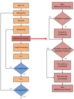
The main processing in the algorithm takes place in two loops. First, the scale of the image and the index within the distortion matrix are set according to the size of the
input image and distortion matrix. The indices of the distortion matrix are used to determine which values within the distortion matrix are used. The distortion vectors are
then calculated in the GetDistortionVector function. Since there is some distortion in the x and y dimensions, both an x and y distortion vector must be computed.
The vectors contain 16 bits to represent their integer portion and 16 bits for their
fractional value. The integer part of the vector is used to determine the correct pixel of the source image and the fractional values are used in a bilinear interpolation
value from the interpolation is then stored in the destination image. This process occurs for all three color channels. Since the main loop of the mapping function only processes
one color channel, a larger loop calls this map1bli function three times. The algorithm is constructed in this way so that different distortion matrices can be used for each color channel if desired.
The basic flow of the algorithm can be seen below in figure 3.3. The
GetDistortionVector function is expanded to show the calculation of these distortion
vectors more clearly. The variables cx, cy, ccx, and ccy are all static variables that are computed within the distortion function. The variables pxindex, pfyindex, xindex, and,
fyindex are used to determine if the value of the distortion vector has changed from a
Figure 3.3 Distortion Algorithm Flow
The input and output images to the function can be seen below in Figure 3.4.
While they appear very similar it can be seen in the input image that there is some curving in the alignment of the white dots. This is corrected in the output image. The image is rotated first so that the computation is more efficient. Also, the output image is
Original Image
[image:29.612.199.420.364.660.2]Output Image
Lastly, a collection of color space conversion modules were adapted from the work of J. Whitesell to further explore the results seen in the dual ARM speedup of the
bilinear and distortion algorithms. These modules are used to convert an image in the RGB color space to the sRGB, XYZ, and finally LAB colorspace. Additionally, the calculation of the numerical gradient of the image is completed. This test reuses
functional sequential C code developed to mimic the operation of these modules in hardware and simply split the operation into two software threads. The modules are used
Chapter 4:
Algorithm Enhancements
Each algorithm is analyzed and carefully enhanced using the aforementioned software methods. First, the bilinear and distortion algorithms are modified by adding
SIMD instructions using the same methodology as E. Welch. These instructions can be found in the arm_neon.h header file [11]. For each of the variables that are to be
calculated using the SIMD instructions, new vectorized variables are constructed. These variables are unsigned integer vectors that have specific sizes based on how many pieces of data are to be calculated at once. For example, a variable of the type uint16x8_t is a
vector with 8 lanes of 16 bit values.
Once the vectors are formed and packed, SIMD instructions are used to execute
basic math manipulations. For example, the vmulq_u16 function takes two uint16x8_t
vectors and multiplies them. The u16 asserts that the vector is split into lanes of 16 bits. The q in vmulq means the vector is four times larger in size than the normal 32 bit
register. A combination of these instructions is used to mimic the computations of the original single core code. The use of these SIMD instructions requires a good
understanding of the code and a strong knowledge of the SIMD instructions. Therefore, the use of these intrinsic functions greatly increases the number of man hours required to implement the code.
The algorithm modifications can be done in several different ways. The basic bilinear interpolation requires four neighbor pixels from the input image to compute one
pixel is to fill four different vectors with the four next required UR, UL, LR, and LL pixels. Using this method four output pixels are computed at the same time and stored in
a single destination vector. However, this method was found to be slow and inefficient by E. Welch. Thus, for the algorithm modifications used in this work, only one output pixel is computed at a time by loading the UR and UL pixels into one vector and the LR and
LL pixels into another. Therefore, the output vector is a 128-bit vector with only 24 bits of real data.
A slightly different strategy is used for the distortion algorithm. The x-loop of the
map1bli function is used to compute four pixels at once instead of just one. This was found to be more efficient for the distortion algorithm versus the bilinear algorithm due to
the increased computational load.
The modifications made to the algorithms for the dual ARM implementations
were more straight-forward. Due to the fact that the both the bilinear and distortion algorithms pixel calculations are easily parallelizable and have no data dependencies, the images can be easily split into different threads.
For the bilinear interpolation algorithm pthreads are used to split the algorithm into two separate tasks. A pthread is the POSIX standard for threads in programming.
The thread represents the smallest sequence of tasks to be handled by a single core. Each task is assigned to a different ARM core. Once the processing completes on each core, the threads are joined and the algorithm terminates. Since in the ARM architecture cores
difficulty with the pthread implementation is that each thread can only call one function that accepts only one input argument.
Fortunately, the bilinear algorithm only calls one function to perform the main computation. Although the function takes many variables as inputs, these variables are packed into one structure. This struct contains information about the image size, start and
stop parameters, and the affinity for each thread. The image is divided in half along the horizontal plane, with the upper and lower portions assigned to core zero and core one,
respectively. Other than the reorganization of the main function and consolidation of the variables into one struct, the actual algorithm is the same. No exotic C constructs or changes are added to the code, and therefore, the changes to the algorithm took very little
time once the thread syntax was complete.
Before execution of the functions the pthread_attr struct has to be configured.
This configuration includes assigning all values in the struct as well as assigning which thread will be run on which core [12].
The distortion algorithm is divided in a very similar way. Since the three color
channels are processed using the same function multiple times, a new set of threads is created and terminated every time the map1bli function is called. Using this method each
of the color channels is split horizontally and sent to each core. The time spent creating and joining the threads is negligible compared to the overall execution time of the entire function. The variables passed to the map1bli function are once again placed in a struct
and passed to each core accordingly.
The two algorithms also required changes for the hardware implementations. The
seamless pixel streaming and no memory read/write time, the output pixels are computed as the input pixels arrive. Since the bilinear and distortion algorithms both need four
input pixels for every output pixel, the computation of the latter needs to take place in four 50 MHz clock cycles.
Due to the amount of resources required, the place and route tools of the Xilinx
tool suite are unable to meet timing constraints if only four stages of logic are used. In order to meet timing, the logic of the algorithm is further pipelined so that less resources
are needed for every state in the algorithm state machine. Since more than four states are needed to execute the bilinear algorithm, the arithmetic clock is raised to 100 MHz. This yielded a total of eight states for the entire bilinear algorithm. In every iteration the
module is operating on the pixels that were loaded into the module four 50 MHz cycles ago. As the module computes the output pixel for that data, it is simultaneously loading
in the pixels to be used in the next loop. In the first and last iterations of the algorithm, four cycles are wasted filling and emptying the pipeline.
A particular requirement for the stream based processing is that all the pixels
needed in an iteration need to be known and available ahead of time. This is alleviated by the fact that the indices of the pixels needed never change from image to image as long as
the interpolation factor and input image size remain the same. Since potential target applications of this research would repetitively process similar images from the same source, this does not present a problem. The indices are found by running the software
The modifications for the distortion algorithm are the same as those for the bilinear algorithm. However, since the distortion algorithm takes more computational
steps, the clock speed is raised to 125 MHz to add two more pipeline stages. Additionally, slight changes had to be made in the arithmetic within the algorithm to make it more adept for hardware implementation.
The hardware implementations followed a number of design for implementation guidelines in order to meet timing requirements. The application of these guidelines
reduce the overall quality of the output, but the speedups obtained compensated for these sacrifices. One example is a division by 3,280 in one of the lines of code of the distortion algorithm. When a divider is implemented in the MCF, the maximum clock frequency
attainable is only 20 MHz which is far below the desired 50 MHz. Therefore, this operation is approximated by a multiplication by 5 and 14 shift rights. The actual value
for each case is shown below.
1
3280= 0.000304878
1 5 ≫ 14 = 0.000305175
The small difference of 0.01% in precision saves a great deal of time when it comes to increasing the frequency of the module. The output image quality is evaluated
correlation between the pixel values in the expected output and the actual output. It is measured on a scale of zero to one, with one representing perfect correlation [13].
The bilinear algorithm is first run on one channel in the MCF and then split into five equal sized strips and placed on the five MCF channels. This is done by giving different input pixel streams for each channel of the MCF and hard coding the correct
loop indices in each channel. Similarly, the distortion algorithm is first run on one channel and then split into three channels, with each processing one color channel. This is
Chapter 5:
Results and Discussions
5.1
Bilinear in Software
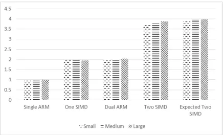
The speedup achieved using the bilinear algorithm can be seen below in Figure 5.1. The baseline comparison for all tests is the execution time for one ARM core using
all compiler optimization flags. Three different sized images are used in the tests; the small image has a resolution of 321x481 (154,401 pixels), the medium image has a resolution of 832x1201 (999,232 pixels), and the large image has a resolution of
[image:37.612.90.526.384.648.2]1080x1920 (2,073,600 pixels.) The 8-bit RGB pixels are all packed into one 24-bit input pixel vector.
Figure 5.1 shows that for each of the image sizes the speedup is nearly constant, with the performance improving only slightly for larger images. This is due to a reduction
in the number of cache misses in the larger images. The dual ARM and single SIMD implementations both achieve a speedup of two. The two SIMD implementation speedup is greater than 3.8 for the largest image size. The column labeled “expected two SIMD,”
represents the speedup from the dual ARM code multiplied with the speedup from the single SIMD code. This column represents the ideal speedup from the combination of the
dual ARM and SIMD algorithm enhancements, while the two SIMD column represents the actual speedup that is achieved. The difference in these columns is attributed to the overhead costs needed to implement the SIMD instructions on two separate cores. It also
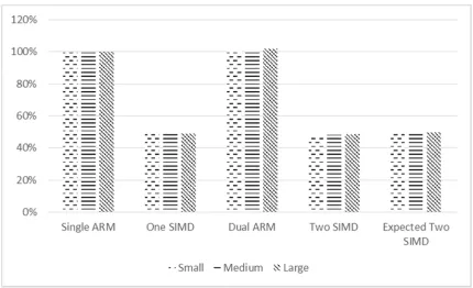
indicates that one NEON core may not perform as well as the other. Although, the SIMD and dual ARM implementation speedups appear to be similar, Figure 5.2 shows that the
Figure 5.2 Bilinear Interpolation Software Efficiency
Efficiency is defined in this work as the actual speedup attained divided by the theoretical speedup. The graph shows that the SIMD implementation is extremely
inefficient compared to the dual ARM code. For the SIMD code, the ideal speedup is a factor of four since the SIMD registers in the NEON coprocessor are four times as wide
as the single ARM registers. The dual ARM implementation has an efficiency of greater than 100% for the bilinear interpolation. The case where the achieved speedup is greater than the ideal speedup is known as super linear speedup. This phenomena can be
explained by further exploring the cache hit and branch mispredict data from each test case. The two SIMD tests have similar efficiency to the single SIMD tests since their
efficiency is bounded by that of the single SIMD.
compatible with the instruction set found in arm_neon.h. For example, some higher complexity functions, such as the square root function, are difficult to implement as they
do not have a specific SIMD instruction. Additionally, one study of enhancing multimedia processing [14], found that SIMD instructions act as a major bottleneck in the code. It was found that 75 to 80 percent of all instructions in a given algorithm are only
supporting the execution of the SIMD instructions. In the study, it was determined that only 12 percent of the desired throughput for the SIMD coprocessor was reached since a
high percentage of the execution was spent supporting the SIMD processing. Although the results in our work are better than that research, a great deal of effort is spent on merely reorganizing the data and packing vectors. If there would be less overhead in
preparing the SIMD vectors, the SIMD instructions would have a much greater impact on performance.
Various other factors such as cache utilization and branch mispredictions also contribute to the observed changes in performance. Figure 5.3 and Figure 5.4 show the cache hit rate and branch misprediction data, respectively, for each image size used in the
Figure 5.3 Bilinear Interpolation Cache Hit Rate
[image:41.612.90.524.376.645.2]The data above shows that the SIMD code has a lower cache hit rate than the dual ARM code and a higher amount of branch mispredictions. This is due to the fact that the
data must be packed and unpacked in SIMD vectors each loop. Therefore, each loop, the data must again be fetched and transferred to the NEON processor. The slight dip in cache hits in the dual ARM program is likely due to the loss of temporal and spatial
locality seen when dividing the image into two separate sections. In the single ARM code, when the processor accesses the cache to fetch a pixel that is used for the middle
section of the image, it most likely will find the data in the cache. However, in the dual ARM code, that section of the image is never placed in cache to begin with since it is being operated on by the other core. In these cases, additional cache misses will be
introduced to the code. Additionally, it can be seen that the amount of branch mispredicts scales almost linearly with the image size. The number of mispredicts for the dual ARM
code is calculated as the average of the total mispredicts on each core. This number is smaller since each core is effectively operating on an image that is half the size. Future research could be done to minimize these mispredicts in the code to further improve
performance.
The perf_event.h header file defines the back end stalls as the stalls in the pipeline
Figure 5.5 Bilinear Interpolation Hundreds of Thousands of Back End Stalls
As can be seen above, these back end stalls also scale with the size of the image. Additionally, the SIMD code again performs worse than the dual ARM code. Although it
seems as though the dual ARM implementation reduces the amount of stalls, the total number of stalls in the program is actually very similar to that of the single ARM code. However, since the stalls in the first half of the image occur simultaneously with the stalls
Figure 5.6 Bilinear Interpolation Execution Time per Pixel in Nanoseconds
This figure shows that the time spent calculating one output pixel in the code is nearly constant across all image sizes. This means that the workload scales linearly as it
Figure 5.7 Bilinear Interpolation Cycles per Instruction
The above figure shows that the intrinsic C functions used in the single ARM and
dual ARM implementations of the code takes the least amount of time to compute. The reason the dual ARM code has the same CPI as the single ARM code is because the
instructions run are the same type as the latter. The vector functions used for the SIMD code take a greater amount of cycles to execute which contributes to the sub-optimal SIMD performance.
The concept of super linear speedup has been examined in many other publications [15], [16], and [17]. Theoretically, the maximum speedup achievable in a
the entire algorithm can be parallelized. If a portion of the code is sequential, then no performance boost is gained from the addition of more processors. The famous Amdahl’s
law, which led to these conclusions, is formally captured below.
= 1 +
This equation shows that the total speedup achievable is based on the fraction of sequential processing in an algorithm, s, compared to the fraction of parallel processing,
p, divided by the number of processors, P. For example, if a program is half sequential, half parallel, and is run on 4 cores, the maximum speedup would be only 1.6 times [15].
However, certain applications, when divided into equal parts may actually utilize
the available resources better than the purely sequential execution of the algorithm. This is due to the reduction in memory access times and program stalls. When the working set
of a particular problem is greater than that of the cache size, many cache misses occur and the overall cache hit ratio suffers. When operating on large images, such as in this work, the amount of pixels being processed could easily be larger than the cache size of
512 KB. When split into smaller threads, the overall strain on the cache can actually be reduced [16].
[17]. In the case of the bilinear and distortion algorithms, these overheads are already miniscule due to the lack of data dependencies mentioned previously.
[image:47.612.130.484.238.518.2]To better understand the super linear speedup present in the dual ARM program, the architecture of the Cortex A-9 processor must be better understood. Figure 5.8 below shows a high-level block diagram of the memory architecture of the A-9 ARM processor.
Figure 5.8 Memory Block Diagram for Cortex A-9
The memory is organized so that each core has its own private data and instruction cache. Next, each core has access to a shared second level cache. Finally, each
core has access to one large shared memory. The image that is being processed is stored in this main memory and each core can access pixels simultaneously. Since the data for
semaphores, or critical sections in memory. Therefore, the only overheads present in the dual ARM program are the overheads needed to create and terminate the threads. This
[image:48.612.91.523.242.405.2]overhead is very small compared to the savings gained from the reduction in cache misses and back end stalls. The benefits of these savings can be seen in Table 1.
Table 1 Bilinear Interpolation Cache and Stall Data
The data above shows the cache misses and back end stalls in hundreds of thousands of events. The execution time spent stalling is found by multiplying the stall cycles by the period of the clock. For the processor used, the clock speed is 667 MHz.
The time saved in the dual ARM program by eliminating the stalls is 115.2 milliseconds. This represents over 15% of the total execution time of the single ARM implementation.
5.2
Distortion in Software
The set of tests for the distortion algorithm matches those run for the bilinear
algorithm, except that processing is only done on one image with a resolution of 3280x2464x3 (24,245,760 pixels). The input image consists of three separate color
channels that are each 3280x2464 8-bit pixels. The distortion algorithm contains more complex computations, including several more multiplications and even a division. Therefore, the execution time for the algorithm is much longer than the bilinear
[image:49.612.89.522.373.633.2]algorithm. Figure 5.9 shows the speedup for the distortion algorithm.
The speedup observed in the SIMD implementation is only 1.67 compared to more than 2.29 for the dual ARM code. This is because the SIMD instructions offer the
greatest performance boost for data parallel instructions. The ideal implementation for these instructions would be for vector operations similar to a GPU working on a matrix. The distortion algorithm contains computations that do not match well with the
advantages of the SIMD implementation, and thus, the speedup achieved is less than expected. The higher speedup in the dual ARM implementation can again be attributed to
[image:50.612.91.524.343.605.2]the cache and branch savings. Figure 5.10 below shows the efficiency of the distortion algorithm.
Figure 5.10 Distortion Software Efficiency
The speedup for the two SIMD model is below 38% due to the poor speedup of
two SIMD cores. The data corresponding to the cache misses, branch mispredicts, and the back end stalls closely follow the data and trends seen in the bilinear algorithm. Table 2
[image:51.612.90.528.227.404.2]shows the data corresponding to these cache misses and branch mispredicts.
Table 2 Distortion Cache and Stall Data
This data demonstrates that the savings in the distortion algorithm are even
greater than those seen in the bilinear algorithm. The 0.9046 seconds saved by reducing the back end stalls represents over 25.1% of the total execution time. This reduction in
stalled time is a major contributor to the speedup observed in the dual ARM implementation.
5.3
GSEG Algorithm in Software
The bilinear and distortion results both show that a large amount of speedup can be achieved with only a few man hours using the multi-threaded approach. Therefore, in
algorithms are used to demonstrate the ease of converting code from a single to multi-core program. The algorithms chosen were developed by J. Whitesell and are modified
from a previously developed GSEG segmentation algorithm. The four algorithms are a sRGB to linear sRGB converter, a linear sRGB to XYZ converter, an XYZ to LAB converter, and a numerical gradient algorithm. In each case the partitioning for the
[image:52.612.91.523.290.550.2]algorithms is done by splitting the algorithm in half in the horizontal direction. Figure 5.11 shows the speedup attained for these tests.
Figure 5.11 GSEG Dual ARM Speedup
The figure shows that large speedups are achievable across a wide range of
typical. To understand the results better, the total computation time is recorded for each core individually. Figure 5.12 shows the percentage of the single ARM execution time
[image:53.612.90.523.158.422.2]that each individual core is actively processing the image.
Figure 5.12 GSEG Percentage of Total Execution Time per Core
This graph shows that the XYZ module that experienced the greatest speedup had
the most balanced workload of all the algorithms. The cores are active almost the same amount of time, which means that there is very little idle time during execution. The LAB and sRGB modules both have computations that depend on the values of the pixels in the
source image. Therefore, the total execution time for each section of the image is unknown at the beginning of execution. When the workload is unbalanced, as in the case
up the algorithms by developing a dynamic method to divide the workload among each core at run time. Although the numerical gradient workload appears to be balanced, the
[image:54.612.90.520.235.495.2]speedup for this algorithm is the lowest of all that were tested. This could be due to the increase in cache misses in the program. Figure 5.13 shows the number of cache misses in each test case.
Figure 5.13 GSEG Cache Hit Rates
The amount of cache misses is constant for the single and dual ARM for all
algorithms except the numerical gradient. It is possible that the numerical gradient algorithm is not a good choice to partition horizontally since it computes the gradient in
5.4
Algorithms in Hardware
Next, the bilinear and distortion algorithms are implemented in the multi-channel framework (MCF). Each algorithm is developed in Verilog and tested in both simulation
and in hardware. The multi-channel implementation for the bilinear algorithm uses all five of the MCF channels, while the distortion algorithm is placed on only three channels,
[image:55.612.88.522.304.569.2]as previously mentioned. Figure 5.14 and 5.15 show the speedup achieved for the various hardware implementations for the bilinear and distortion algorithms respectively.
Figure 5.14 Bilinear Interpolation Speedup in Multichannel Framework
modifications. The speedup for the bilinear and distortion algorithm multi-channel implementations are 5.74 and 5.57 respectively.
Figure 5.15 Distortion Speedup in Multichannel Framework
The hardware results show that custom FPGA implementations yield greater performance than advanced software techniques in certain situations. The speedups for the software are slower since a large amount of overheads are introduced in the
abstraction layers between the hardware of the processing core and the executable files of the algorithms. When adjusting for the fact that the clock speed of the ARM core is 13.34
times faster than the hardware clock, the MCF implementation has a relative speedup of 76.57 over the software.
Table 3 shows the utilization data for the various hardware implementation
Table 3 Hardware Utilization Data
Slices FFs LUTs BRAM DSP48 BUFG BUFR MMCM
Test Modules:
Bilinear (1 Channel) 12,155 29,506 25,790 75 36 11 2 2
32% 9% 17% 18% 4% 34% 5% 16%
Bilinear (5 Channel) 12,535 32,193 29,716 75 184 11 2 2
33% 10% 19% 18% 23% 34% 5% 16%
Distortion (1 Channel) 12,210 29,855 26,100 81 31 11 2 2
32% 9% 17% 19% 4% 34% 5% 16%
Distortion (3 Channel) 13,142 31,910 28,619 93 93 11 2 2
34% 10% 18% 22% 12% 34% 5% 16%
Available in
xc6vlx240t: 37,680 301,440 150,720 416 768 32 36 12
The data in Table 3 shows that the Virtex-6 is not even half utilized in the most
extreme test cases. This means even more complex algorithms can potentially be implemented on the MCF. However, as the number of channels in the distortion is increased, the place and route steps of implementation begin to take much more time.
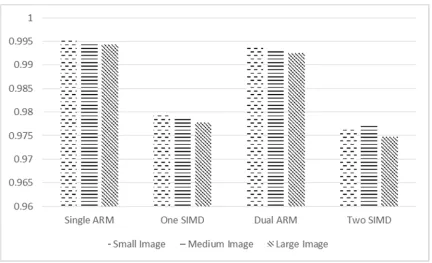
Table 4 2-D Correlation Coefficients for each Algorithm
The data shown in the table above demonstrates that even though some
approximations are made in the hardware modules, the image quality still remains at an acceptable level.
5.5
Tradeoffs in Enhancing an Algorithm
The tradeoffs in designing and enhancing an algorithm pertain to three main factors: resources available, execution time versus accuracy, and effort spent on
improving the algorithm.
The amount of resources available is a very important factor to consider when designing an algorithm. The single ARM implementation of all the algorithms tested in
this work requires the least amount of resources. The introduction of SIMD instructions and multi-threaded processing required extra processors to be included in the design. In
MCF channels and other modules such as floating point units may be necessary in other algorithms. It is important to keep track of how much area is available as well as how
many resources are provided on an FPGA when designing a module in HDL.
In terms of execution time, the results of this work clearly show that developing an algorithm in hardware is the way to achieve the greatest speedup. This is due to the
customization and application specific design that is feasible when using hardware. Since only basic communication blocks like the PCIe bus are needed to load the data and export
it, no real processor fetch and execute cycle is needed to process data. The ability to tailor an FPGA module to do exactly what is required for a given algorithm yields impressive results when compared to the execution time of algorithms in software, even at much
higher clock speeds.
If accuracy is the most important metric, a software implementation of an
algorithm is the best approach. Unfortunately, hardware implementation of complex arithmetic such as division is not feasible on an FPGA at reasonable clock speeds. Additionally, creating a true floating point arithmetic logic unit (ALU) would be costly in
terms of resources and speed. Therefore, certain shortcuts and approximations have to be made when adapting algorithms for software. By making these shortcuts in hardware, the
overall image quality suffers. Even though this reduction in quality is a miniscule amount, it can still be noticeable to the human eye. If the output of one hardware module is fed into the input of another module, the compounding of the error may become severe
as in the cases of the GSEG color conversion engine of J. Whitesell’s work [3]. To ensure the output image quality is maintained, one of the software methods of speeding up an
Lastly, the amount of man hours that can be spent on improving an algorithm must be taken into consideration. The work here shows that a large speedup is attainable
with only a slight modification of an algorithm using pthreads. If a designer has to implement a larger algorithm in HDL or with SIMD instructions, the process could take many days if not weeks. This tradeoff is an important one to keep in mind when choosing
to improve existing algorithms.
Although the algorithms chosen in this work are highly parallelizable, other image
processing techniques may include more data dependencies. In these cases, the multithreading design may not work as well. It is possible that in some cases, such as matrix math, the use of SIMD instructions could potentially yield the best results. It is
Chapter 6:
Conclusion
In conclusion, the results of this work show that a wide array of options exist in hardware and software to speed up color image processing algorithms. The main tradeoffs in choosing which method to use are: required resources, output image quality,
and man-hours necessary to modify the algorithm to achieve the desired speedup. If a perfect recreation of the output image is necessary the best approach would be to
implement the code on a multi-core chip. If there is a large amount of data parallelism present within an algorithm and vector operations are well suited, SIMD instructions can be used to achieve great speedups. If it is acceptable for the output image quality to be
slightly degraded in order to attain large speedups then implementing the algorithm on an FPGA or ASIC design is most likely the best approach. Each method has its advantages
References
[1] R. Toukatly, "Dynamic partial reconfiguration for pipelined digital systems: a case study using a color space conversion engine," M.S. thesis, Dept. Elect. Eng., Rochester Inst. of Technology, Rochester, NY, 2011.
[2] Mykyta A., Patru D., Saber E., Roylance G., and Larson B. “Reconfigurable
Framework for High-Bandwidth Stream-Oriented Data Processing,” SOC Conference, 2012 IEEE International, 177-183(2012).
[3] Whitesell, J; Patru, D.; Saber, E.; Roylance, G.; Larson B. “Design for
implementation of color image processing algorithms” Proc. SPIE 9015, Color Imaging XIX: Displaying, Processing, Hardcopy, and Applications, 90150D (January 8, 2014).
[4] Welch, E.; Patru, D.; Saber, E.; Bengtson, K., "A study of the use of SIMD instructions for two image processing algorithms," Image Processing Workshop (WNYIPW), 2012 Western New York , vol., no., pp.21,24, 9-9 Nov. 2012.
[5] Libo Huang; Li Shen; Zhiying Wang; Wei Shi; Nong Xiao; Sheng Ma, "SIF: Overcoming the limitations of SIMD devices via implicit permutation," High
Performance Computer Architecture (HPCA), 2010 IEEE 16th International Symposium
on , vol., no., pp.1,12, 9-14 Jan. 2010.
[6] Jie Zhao; Yongmin Yang; Ge Li, "Real-time Image Processing System Based on
[7] Ye Li; Qingming Yao; Bin Tian; Wencong Xu, "Fast double-parallel image processing based on FPGA," Vehicular Electronics and Safety (ICVES), 2011 IEEE
International Conference on , vol., no., pp.97,102, 10-12 July 2011.
[8] Gabiger, A.; Kube, M.; Weigel, R., "A synchronous FPGA design of a bilateral filter for image processing," Industrial Electronics, 2009. IECON '09. 35th Annual Conference
of IEEE , vol., no., pp.1990,1995, 3-5 Nov. 2009.
[9] Xilinx “Zynq-7000 All Programmable SoC,” December 2013. [Online]. Available:
http://www.xilinx.com/products/silicon-devices/soc/zyqn-7000/.
[10] ARM “Cortex-A9 Processor,” 2014. [Online]. Available: http://www.arm.com/ products/processors/cortex-a/cortex-a9.php.
[11] GNU “ARM NEON Intrinsics,” 2014. [Online]. Available: http://gcc.gnu.org/ onlinedocs/gcc/ARM-NEON-Intrinsics.html.
[12] Barney, Blaise “POSIX Threads Programming” 2014 [Online]. Available: https://computing.llnl.gov/tutorials/pthreads/.
[13] Papoulis, A., Pillai, S. U., [Probability, Random Variables and Stochastic Processes],
McGraw-Hill, New York, 210 (2002).
[14] Talla, D.; John, L.K.; Burger, D., "Bottlenecks in multimedia processing with SIMD
style extensions and architectural enhancements," Computers, IEEE Transactions on , vol.52, no.8, pp.1015,1031, Aug. 2003.
[15] Shan, Jing, “Superlinear Speedup in Parallel Computation,” CCS, Northeastern
[16] Ristov, S.; Gusev, M., "Superlinear speedup for matrix multiplication," Information Technology Interfaces (ITI), Proceedings of the ITI 2012 34th International Conference
on , vol., no., pp.499,504, 25-28 June 2012.
[17] Kwak, H.; Lee, B.; Hurson, A.R.; Suk-Han Yoon; Woo-Jang Hahn, "Effects of multithreading on cache performance," Computers, IEEE Transactions on , vol.48, no.2,
Appendix A:
Hardware and Software Used
6.1
Hardware
• Test Laptop to Compile Code o OS: Ubuntu LTS 12.04
o CPU: Intel Core i7-3537U @ 2.00GHz o RAM 8 GB
• FPGA Development Board o Xilinx ML605
o FPGA Family: Virtex-6 LXT o Device: xc6vlx240t-1ff1156-1
o Programming Interface: JTAG over USB o Debugging Interface: UART over USB
• Development and Implementation PC: o OS: Microsoft Windows 7 (x86, SP1) o CPU: Intel Core 2 Duo, 2.66 GHz o RAM: 3 GB
• Testing PC:
o OS: Linux Fedora 10 (2.6.27.5 Kernel version) o CPU: Intel Core 2 Duo, 2.40 GHz
o RAM: 2 GB
o PCI-Express slot populated with ML605 FPGA card.
6.2
Software
• Windows 7 Development PC:
o Xilinx ISE Design Suite: 13.1 System Edition (incl. April 2011 patch) o ISE Project Navigator
o PlanAhead (incl. PR license) o iMPACT
o Cygwin
GNU C Compiler GNU Make o Tera Term v4.71 o Ubuntu
![Figure 2.1 Example of SIMD Addition, Reproduced from [4]](https://thumb-us.123doks.com/thumbv2/123dok_us/42645.3828/15.612.128.479.473.668/figure-example-simd-addition-reproduced.webp)
![Figure 2.2 R. Toukatly’s Dual-Pipe PR CSC Engine, Reproduced from [1]](https://thumb-us.123doks.com/thumbv2/123dok_us/42645.3828/19.612.118.496.503.681/figure-toukatly-dual-pipe-pr-csc-engine-reproduced.webp)
![Figure 2.3 Multichannel Framework, Reproduced from [2]](https://thumb-us.123doks.com/thumbv2/123dok_us/42645.3828/20.612.172.461.364.587/figure-multichannel-framework-reproduced-from.webp)
![Figure 3.1 Bilinear Interpolation Example Reproduced from [4]](https://thumb-us.123doks.com/thumbv2/123dok_us/42645.3828/24.612.110.520.208.360/figure-bilinear-interpolation-example-reproduced.webp)

![Figure 3.4 Distortion Algorithm Example Reproduced from [4]](https://thumb-us.123doks.com/thumbv2/123dok_us/42645.3828/29.612.199.420.364.660/figure-distortion-algorithm-example-reproduced-from.webp)