City, University of London Institutional Repository
Citation
:
Rahman, B. M. ORCID: 0000-0001-6384-0961, Mishra, J. K. and Pan, C.
(2018). Design and optimization of photonic devices and optical fibers for space-division
multiplexing. Proceedings of SPIE, 10560, 1056007.. doi: 10.1117/12.2291522
This is the accepted version of the paper.
This version of the publication may differ from the final published
version.
Permanent repository link:
http://openaccess.city.ac.uk/20504/
Link to published version
:
http://dx.doi.org/10.1117/12.2291522
Copyright and reuse:
City Research Online aims to make research
outputs of City, University of London available to a wider audience.
Copyright and Moral Rights remain with the author(s) and/or copyright
holders. URLs from City Research Online may be freely distributed and
linked to.
City Research Online:
http://openaccess.city.ac.uk/
publications@city.ac.uk
Design and optimization of photonic devices and optical fibers for
space-division multiplexing
B. M. A. Rahman*
a, Jitendra K. Mishra
b, and Chao Pan
a aDept. of Electrical and Electronic Engineering, City, University of London, London EC1V0HB,
UK;
bDept. of Electronics and Telecomm. Engineering, National Institute of Technology, Raipur,
492010, India
ABSTRACT
Although, the technological breakthroughs such as WDM had allowed the capacity per fiber to be increased around ten-fold every four years in the past decade, however, the capacity of the optical communication systems based on these transmission technologies is slowly becoming saturated. To satisfy the exponential growth of the Internet traffic, for the next generation short reach systems, including data center transmission and optical interconnect (OI) applications, the space-division multiplexing (SDM) can be a way forward. The SDM technology based on the multicore fiber (MCF) has recently attracted much attention as a potential approach. In this paper, design strategy of computer-compatible 8-core trench-assisted MCF (TA-MCF) is presented to reduce the intercore crosstalk. Moreover, the influence of butt-coupled TA-MCF OI on coupling loss is also discussed. On the other hand, another alternative approach, the mode division multiplexing (MDM) is also showing promise and mode (de)multiplexer is one of the key devices in such a MDM system. Designs of mode splitters using asymmetric directional couplers for the fundamental quasi-TE (TM) mode with the higher order quasi-TE (TM) modes (de)multiplexer including the 𝐇𝒚𝟐𝟏 (𝐇𝒙𝟐𝟏), 𝐇𝒚𝟑𝟏(𝐇𝒙𝟑𝟏, 𝐇𝒚𝟒𝟏(𝐇𝒙𝟒𝟏, and 𝐇𝒚𝟓𝟏(𝐇𝒙𝟓𝟏)
modes are optimized by using a full-vectorial H-field finite element method.
Keywords: Multicore fibers, optical interconnects, space-division multiplexing, mode division multiplexing, mode splitters, slot waveguide
1.
INTRODUCTION
Traffic of data in modern data centers is growing exponentially and the increase is driven by high-definition video sharing, network communications and many other bandwidth hungry interconnect applications [1]. Limitations of traditional copper interconnects at high frequency make optical interconnect (OI) technologies a promising candidate for ultra-high speed signal transmission with lower cost and power consumption. In order to increase the transmission capacity, parallel OIs are extensively deployed using fiber ribbons or individual fibers but may not be enough to exploit huge optoelectronic bandwidth disparity existing between the requirement and availability of futuristic data centers and high performance computing systems [2]. OI configuration based on multicore fiber (MCF) has been expected to be a viable technology to overcome the bandwidth density drives of short-reach optical transmission systems [3]. Space-division multiplexing (SDM) technology using MCF shows a high potential to combat the explosive growth in data volume requirement of next-generation high-performance short reach OIs. Besides increasing the transmission capacity, the stimulus behind pursuing SDM realized by MCF involves reducing cable size limitation and minimizing the link cost and power budget in bandwidth intensive box-to-box, rack-to-rack, board-to-board and chip-to-chip interconnect applications [4].
compatible with number of parallel lanes in data buses required in high performance computers as well as on-chip integrated photonic systems comparing to MCF with popular hexagonal or ring structure [3, 4]. Furthermore, achieving efficient coupling of MCF to standard single core fibers (SCFs) is a significant challenge which limits the application of MCF as OI. To solve this problem, various types of fan-in fan-out (FIFO) schemes have been recently proposed, such as fiber bundled type [9], physical contact method [10], grating coupler array based FIFO [11], and coupling with lens optics [12]. However, it has also been reported that the least squares boundary residual (LSBR) method [13] would be more efficient and accurate to use to analyze the coupling losses due to misalignments between MCF and SCF.
In this paper, an 8-core heterogeneous TA-MCF with rectangular arrangement is being proposed for application in next generation exa-bandwidth OIs. The effects of quantitative and qualitative trench design parameters on the intercore XT are investigated by using a rigorous full-vectorial H-field finite element method (FEM) [14]. The optimal design is based on strong mode confinement capability of TA-MCF OI to reduce the intercore XT. Subsequently, the modal solution approach based on the numerically efficient FEM [14] and the LSBR method [13] have been used to calculate the coupling loss caused by the misalignment between TA-MCF OI and SCF.On the other hand, design optimization of the asymmetric directional coupler (ADC)for SOI mode (de)multiplexer is presented by using the full-vectorial H-field FEM. The width of multi-mode nanowire is optimized following the phase matching condition. As a result, the fundamental mode of access single mode nanowire (SMNW) can be converted to higher order mode and coupled to the multi-mode nanowire (SMNW). Separation between these two nanowires is determined through tolerance analysis which is simulated by the LSBR method. The influence of fabrication tolerances is also discussed thoroughly in this paper. The result shows that the narrow separation of 100 nm should be employed and the fabrication of the SMNW should be strictly accurate with the error of less than +5 nm as the structure is very sensitive to the change of nanowire (NW) width.
2.
THEORY
The full-vectorial numerical method used here is an H-field based FEM, one of the most accurate and numerically efficient approaches. The formulation is based on the minimization of the full H-field energy functional [14],
* 1 *
2 [( ) ˆ )
ω
ˆ
p dxdy dxdy
∬
∬ *
H H H H
H H
(1)
where H is the full-vectorial magnetic field, * denotes a complex conjugate and transpose, ω2 is the eigenvalue (ω being the angular frequency), p is a weighting factor for penalty term to eliminate spurious modes and𝜀 and 𝜇 are permittivity and permeability tensors, respectively.
Figure 1(a) shows a schematic cross section of proposed MCF based OI, inside which cores are arranged in rectangular arrays. The index profile of a core with trench is shown in Fig. 1(b). All cores in TA-MCF OI are arranged with core to core pitch (Λ) and distance between the two rows is 2Λ. In the Fig. 1(b), r1, r2, r3, Δ1, Δ2, and W represents the core
[image:3.595.154.447.536.679.2]radius, the distance between the center of core and the inner edge of trench, the distance between the center of core and the outer edge of trench, the relative refractive-index difference between core and cladding, the relative refractive-index difference between trench and cladding, and the width of the trench layer, respectively.
2.1 Calculation of Cmnand XT between TA-MCF OI cores
In order to obtain the XT between two adjacent cores in TA-MCF, coupled power theory [5] is employed. But before that the value of mode coupling coefficient Cmn between two neighboring cores of MCF OI with trench index profile is
investigated at first. The expression of coupling coefficient between two cores is given as [15]
2 2 *
0
* * * *
.
,
2 .
n m n
mn
mx my my mx nx ny ny nx
N N E E dxdy
C
E H E H dxdy E H E H dxdy
(2)where ω is an angular frequency of sinusoidally varying electromagnetic fields, and ε0 is the permittivity of free-space.
The pair m and n is either (1, 2) or (2, 1). E and H represent the electric and magnetic fields respectively. A rigorous full-vectorial H-field Finite Element Method (FEM) [14] is used in this work to calculate the mode coupling coefficient Cmn.
The mode coupling coefficients between the cores are used to evaluate the power coupling coefficient [5]. The XT between two cores of TA-MCF OI over a length L is estimated by the coupled power theory as [5]
tanh( mn ),
XT h L (3)
where hmnrepresents the average power coupling coefficient. The full-vectorial field obtained by using the H-field based
FEM is utilized to calculate Cmnand hmnand finally the XT.
2.2 Calculation of coupling loss due to misalignment
When butt-coupling to a MCF OI, it is desirable that the beam divergence from the MCF is matched to the spot size of the standard SCF for precise core alignment and low loss coupling. In order to calculate the power coupling between MCF OI and SC-SMF computationally efficient vector FEM [14] and LSBR method [13] is used. The LSBR method looks for a stationary solution to satisfy the continuity conditions by minimizing the error energy functional, J, as given by [13]
2 2 2
0
. ,
I II I II
t t t t
J E E Z H H d
(4)where Z0 is the free-space impedance, EtI, II t
E , I
t
H and II t
H are the transverse components of the electric and magnetic fields in side I and side II and α is the dimensionless weighting factor to balance the electric and magnetic components of the error functional J. The integration is carried out at the junction interface, Ω , between a straight MCF OI and a conventional SCF.
2.3 Theory of mode splitters using asymmetric directional couplers
3. NUMERICAL RESULTS
3.1 Optimization of 8-core MCF
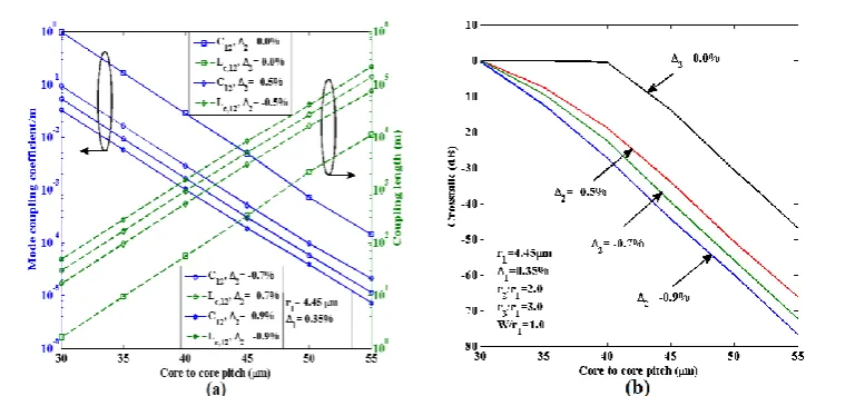
Fig. 2. (a) Variations of mode coupling coefficient and coupling length with the core to core pitch for an 8-core TA-MCF, for different Δ2, when r2/r1=2.0, r3/r1=3.0, and W/r1=1.0 and (b) variations of crosstalk with core to core
pitch for an 8-core TA-MCF, for different Δ2 values.
Figure 2(a) illustrates the numerically simulated C12 and Lc,12 of homogeneous TA-MCF OI with the Λ at a optical
wavelength of 1550 nm where the relative trench position r2/r1 and the relative trench width W/r1 are taken as 2.0 and
1.0, respectively and the core radius r1 and relative refractive-index difference between core and cladding are fixed at
4.45 μm and 0.35%, respectively. The variations of C12 and Lc,12 are simulated for Δ2= 0%, −0.5%, −0.7%, and −0.9%. It
can be observed from Fig. 2(a) that the C12 for homogeneous TA-MCF OI decreases with increase in Λ and exhibits very
low C12 compared to step-index 8-core MCF. It can also be noted that the C12 decreases with increasing the value of
low-index trench Δ2. When the Λ and Δ2 is fixed at 45 μm and −0.9% respectively, then the C12 and Lc,12 values are on the
order of 0.0001 m─1 and 104 m, respectively. Figure 2(a) clearly demonstrates that for higher value of low-index trench Δ2 we can get the minimum C12and maximum Lc,12.
Figure 2(b) shows the variations of XT with Λ for 8-core homogeneous TA-MCF OI for Δ2= 0%, −0.5%, −0.7% and
−0.9%.It shows that for a given Δ2, XT12 decreases with increase in Λ and XT12decreases with increasing the value of
low-index trench Δ2. Moreover, for same Λ of 45 μm and at the condition Δ2= −0.5%, XT12 in TA-MCF OI is 20 dB
smaller as compared to step-index counterpart. It can be noted from Fig. 2(b)that the required Λ for a homogeneous TA-MCF OI is 43.7 μm if the trench parameter Δ2 is fixed at −0.7%, corresponding to the target XT level of −35 dB. On the
other hand, the required Λ for a homogeneous TA-MCF OI is 42.3 μm if the trench parameter Δ2 is fixed at −0.9%. This
value is 9.4 μm lower than the Λ required for step index 8-core MCF. From this comparison, we can find clearly that the TA-MCF OI gives rise to better XT performance and arrangement can be more compact.
To clearly demonstrate the effect of trench on Cmn, Lcand XT, dominant HY field of the fundamental quasi-TE, 11 y
H mode for 8-core step index and TA-MCF is plotted in Fig. 3(a). A rigorous vector H-field FEM [14] is employed to obtain the field distributions of trench index core for Δ2= 0%, −0.5%, −0.7% and −0.9%, shown in Fig. 1(b). It can be observed
from Fig. 3(a) that the deployment of trench layer around each core can depress the field distributions, far away from the core. Here outside the core (beyond r1) field varies exponentially, which is shown by a line with a constant slope when
semi-log scale is used. The slopes between r1 to r2 and beyond r3 are the same as local index in these regions were same.
However, when refractive index in the trench region, shown here between r2 and r3 is reduced, the slope of the field
variation also shows faster field reduction. Moreover, field reduces faster between distance r2-r3 (where trench is located)
if low-index trench Δ2 is higher. Therefore, the spatial overlap of the electromagnetic field between two adjacent cores of
TA-MCF OI will be small, resulting Cmn and XT will reduce even if the Λ is very small.
Afterwards, in order to investigate the influence of the location of trench on Lc and XT characteristics, numerical
simulations based on rigorous vector H-field FEM is illustrated in Fig. 3(b). Here, the fixed values for r1, Δ1, Λ, and
[image:5.595.101.490.103.281.2]the location of the trench layer. It can be observed in Fig. 3(b), that the Lc increases with r2/r1 and for a given location of
the trench with high value of low-index trench Δ2. Moreover, XT12 of an 8-core homogeneous TA-MCF OI decreases
with increasing r2/r1 and for a given location of trench with high value of low-index trench Δ2. It can be noticed that,
when Λ is fixed at 45 μm, it is possible to obtain XT12 less than −35 dB under two conditions – (i) r2/r1= 1.6, Δ2= −0.7%,
(ii) r2/r1= 1.4, Δ2= −0.9%. Although, the low-index trench Δ2= −0.9% may be preferable for XT reduction but TA-MCF
OI fabrication using regular outside vapor deposition (OVD) and vapor axial deposition (VAD) processes, Δ2 value can
be limited to be around −0.7% [8]. Therefore, to find out the optimized arrangement of trench location with reduced Λ and to make sure the trench is not overlapping with the adjacent trenches, we can increase the value of r2/r1 to 2.0.
Fig. 3. (a) HY field of the fundamental mode for 8-core step index and TA-MCF and (b) variation of coupling
[image:6.595.97.477.186.353.2]length and crosstalk with the r2/r1 for 8-core TA-MCF OI.
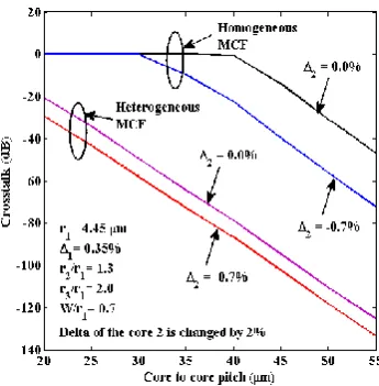
Fig. 4. Variations of crosstalk with with the core to core pitch for an 8-core heterogeneous TA-MCF, when Δ2 =
-0.7%, r2/r1=1.3, r3/r1=2.0, and W/r1=0.7.
Afterwards, in order to design a more compact arrangement an 8-core heterogeneous TA-MCF OI is considered, where the delta of the core 2 is changed by 2% (see Fig. 1(a)). Figure 4 illustrates the variations of XT with Λ for an 8-core heterogeneous TA-MCF OI for Δ2 = −0.7%, r2/r1=1.3, r3/r1=2.0, and W/r1=0.7. It can be observed from Fig. 4 that the
XT for heterogeneous TA-MCF OI decreases with increase in Λ and exhibits very low XT compared to 8-core homogeneous TA-MCF. It can also be noted that for same Λ of 35 μm and with Δ2= −0.7%, XT in heterogeneous
[image:6.595.210.383.414.590.2]heterogeneous step-index MCF OI is 25.3 μm, corresponding to the target XT level of −35 dB. On the other hand, the required Λ for a heterogeneous TA-MCF OI is 22.1 μm if the trench parameter Δ2 is fixed at −0.7%. This value is 21.6
[image:7.595.221.391.131.303.2]μm lower than the Λ required for a homogeneous TA-MCF and so the core arrangement can be more compact than MCF reported recently with high density core for OI applications.
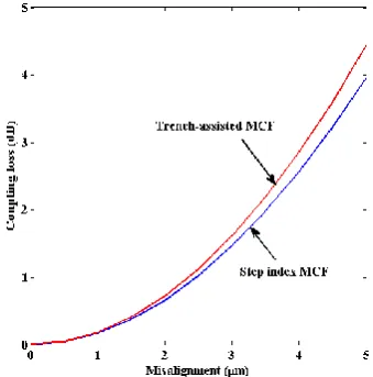
Fig. 5. Variations of coupling loss with misalignment for step index MCF and TA-MCF OI.
Whenever, we couple a MCF to a standard SCF, it may not be perfectly aligned and effect of possible misalignment is studied next. Figure 5 illustrates the variations of coupling loss caused by the misalignment for step index MCF and TA-MCF OI. Here, we fixed the value for r1, Δ1, Δ2,r2/r1, r3/r1,and W/r1, which are assumed as 4.45 μm, 0.35%, −0.7%, 1.3,
2.0, and 0.7, respectively. It can be noticed that the 3 dB coupling loss for TA-MCF and step index MCF is obtained at the misalignment of 4.1 μm and 4.3 μm, respectively. As it can be observed in Fig. 5, coupling loss increases exponentially with misalignment for the both structure, Δ2= 0% and Δ2= −0.7%. But however, for TA-MCF (Δ2= −0.7%)
the coupling loss is only slightly higher compared to step index MCF (Δ2= 0%). This observed behavior can be explained
by noting that trench assisted core increases the modal field confinement (see Fig. 3(a)) substantially. Therefore, coupling losses increase moderately as the spot size decreases. It can also be noted that the coupling loss for step index MCF and TA-MCF OI are almost identical for misalignment of 0 to 1.2 μm, which proves the feasibility of TA-MCF OI for their practical applications.
3.2 Optimization of mode splitters using ADC
(a) (b)
Fig. 6. (a) Variations of the effective indices of eigen modes with the SOI NW width. (b) Diagram of an ADC for mode (de)multiplexer.
First, the effect of NW width on the phase matching condition is studied. Variations of the effective indices, neff of the
eigen modes including fundamental quasi-TE H𝑦11 mode, fundamental quasi-TM, H𝑥11, modeand higher order, H𝑦21, H𝑦31,
[image:7.595.118.475.467.631.2]observed that the effective indices of any quasi-TE or quasi-TM modes of one guide may be made equal to another mode of a second guide when the value of the effective index value is low, as shown by a black dotted line. However, when the value of the effective index is larger enough, for example, bigger than 2.0, only quasi-TE modes of SOI nanowire with different specific widths may have the same effective index, indicated by a black dashed line. Considering the above observations, the schematic cross section of ADC for mode (de)multiplexer is shown in Fig.6 (b), consisting of two Silicon nanowire with unequal widths but of equal height, H. All the parameters can be easily controlled by mask design, so it will be relatively easy for fabrication. The width of the SMNW which is used for access is identified by WS, while the width of the MMNW is identified by WM. The separation between two waveguides is taken as S.
Fig. 7. Variation of the phase-matching point between the H𝑦21 and H𝑦11 modes with the mesh number.
Accuracy of a design critically depends on the solution accuracy. Thus, accuracy of phase matching is also studied here. We calculated the effect of mesh size on identifying the width of the MMNW for phase matching with a access SMNW. Variation of the width of MMNW when its H𝑦21 mode is phase matched with the H𝑦11 mode of the SMNW with the width of 400 nm, along the mesh size used and improvement by Aitken’s extrapolation are shown in Fig.7, as an example. For mesh size of 200 × 200, the propagation constant of the SMNW is 8.51799 μm−1, shown by green horizontal line and it suggests WM should be 827 nm, shown by green slanted line. On the other hand, as the mesh size increased to 400 ×
400, new phase matching condition sugget that that WM should be equal to 815 nm, shown by a blue slanted line. When
the mesh size is increased further to 800 × 800, the red solid line in Fig.7 shows that the required phase matching width of the MMNW is now 811 nm. We calculated Aitken’s value of the propagation constant from three values above as
their mesh division ratios are identical, plotted by black slanted line. The phase matching WMNW width needs to be 810 nm, reduced further but by only 1 nm. It can be seen that the phase-matching width decreases as the mesh size increases and the difference between the value of FEM approach with low mesh size of 200 × 200 and that of more accurate Aitken’s extrapolation is about 17 nm. It is clear from this that the accurary of the numerical approach used is very important. As the performance of any ADC critically depends on the accuracy of the phase matching, later on, it will be shown the effect of the solution or fabrication accuracy on the performance. Design by a less accurate methord or less accurate mesh may not be able to achieve expected performance, and thus a viable design.
The phase-matching widths for the H𝑦31, H𝑦41, and H𝑦51modes with the H𝑦11 mode, and H𝑥21, H𝑥31, H𝑥41and H𝑥51modes with
the H𝑥11 mode are also calculated by using the Aitken’s extrapolation and shown in Tables I. The phase matching width
of H𝑦31 mode MMNW is 1238 nm when the width of the SMNW is taken as 406 nm. For the SMNW with the width of
379 nm, the necessary phase matching width of the H𝑦41 mode MMNW is 1551 nm. The result discussed above shows
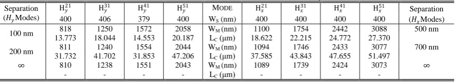
TABLEI
PHASE MATCHING WIDTHS AND COUPLING LENGTHS FOR DIFFERENT HIGHER ORDER𝐻𝑦AND 𝐻𝑥MODES AND SEPARATIONS Separation
(𝐻𝑦Modes)
H𝑦21 H𝑦31 H𝑦41 H𝑦51 MODE H𝑥21 H𝑥31 H𝑥41 H𝑥51 Separation 400 406 379 400 WS (nm) 400 400 400 400 (𝐻𝑥Modes)
100 nm 818 1250 1572 2058 WM (nm) 1100 1754 2442 3088 500 nm
13.773 18.044 14.553 20.187 LC (μm) 18.622 22.215 24.772 27.370
200 nm 811 1240 1554 2044 WM (nm) 1094 1746 2433 3077 700 nm 31.732 41.702 31.853 47.206 LC (μm) 37.585 43.843 47.655 51.497
∞ 810 1238 1551 2043 WM (nm) 1089 1739 2424 3073 ∞
[image:8.595.58.524.468.552.2]phase matching for isolated guide. When two identical guides are coupled, they always remain phase matched. However, for two nonidentical but phase matched guides, their phase matching condition changes with their separation due to unequal loading
.
The coupling lengths from the propagation constants of different higher order modes and separations when satisfying the phase matching condition are also calculated and shown in Table I. The coupling length is longer when the separation is increased.After calculating the widths of MM guides necessary for phase matching, together with the coupling length for the ADCs, the LSBR method is applied to calculate the power transmission of the structure and to evaluate the effect of possible fabrication tolerances. This approach yields the transmitted modal coefficient of the even supermode, Ce, and
the odd supermode, Co,excited in the SMNW and ADC interface to satisfy the continuity of the tangential Electric and
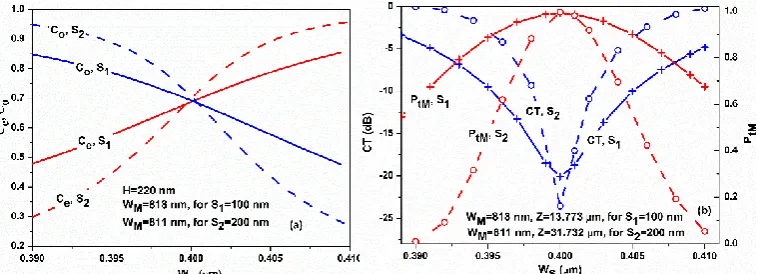
Magnetic fields. The ADC section of H𝑦11 mode and H𝑦21 mode (de)multiplexer is considered next, as example. Variation
of these two supermodes’ coefficients with the SMNW width for different separations S1=100 nm, S2=200 nm are shown
in Fig.8 (a). The phase matching widths of the MMNW for each separation are used in these cases. It can be observed that the coefficient of the even mode increases, and the coefficient of the odd mode decreases, when the SMNW widens. For S2=200 nm, the values of Ce, Co are 0.69927 and 0.70730, respectively, at phase matching and are very close to
1/ 2 when both the supermodes carry half power, ideal values for weak coupling. In this case, 99.5% power can be transferred from NW to the ADC. For S1=100 nm, the values of Ce, Co are decreased a little to 0.69616 and 0.68406,
respectively, at phase matching, and 99% power can be transferred from NW to the ADC. It can be observed that, for larger separation, more power will be transferred. However,it is clear that for smaller separation, Ce, Co is less sensitive
[image:9.595.111.491.308.445.2]to the change of the SMNW width. Both of these two aspects should be considered for a practical design.
Fig. 8. Variations of the transimitted modal coefficients Ce, Co (a) and variations of the normalized output power in the MMNW, Ptm, and crosstalk, CT
(b) with the width of SMNW, WS for two different separations, S1, S2.
Setting the coupling length, LC, as the length of the ADC section, Z, two excited supermodes would be out of phase at
this distance. As a result, the H𝑦11 mode field in the SMNW will disappear, and instead, the phase-matching higher order mode field in the MMNW will be added up, as a result of vector addition of these two supermodes. The power in each NW can be calculated from the modal coefficients, phase difference and their full vectorial mode profiles. Variations of the power of the H𝑦11 mode in the SMNW and that of the H𝑦21 mode in the MMNW with the change of the SMNW width for different separation S1, and S2, are shown in Fig.8 (b). The device length and the MM waveguide width here are kept
fixed to the idealized design for each separation. It is shown that the maximum normalized power of the H𝑦21 mode, PtM,
in MMNW which indicates the normalized mode conversion power, drawn by red solid and dashed lines are about 0.990 and 0.995 for S1=100 nm, and S2=200 nm, respectively. It means more than 99% power of the input H𝑦11 mode wave in
SMNW is converted to the H𝑦21 mode wave in MMNW successfully. The minimum amount of the normalized
unconverted H𝑦11mode power in the SMNW which would be defined as crosstalk, CT, plotted by blue solid and dashed lines, and these are about -20.01 dB and -23.52 dB for S1=100 nm, and S2=200 nm, respectively. It can also be observed
that the variation of the SMNW width away from the ideal phasing matching width will cause a significant deterioration of the performance, especially for a wide separation. For +10 nm fabrication error, PtM will reduce to 0.611 and 0.009 for
S1=100 nm, and S2=200 nm, respectively. Therefore, the structure with the narrow separation should be chosen for
design, as its performance is less sensitive than that of the one with a wider separation. It is clear that when the fabrication error of the SM guide is less than +5 nm, the PtMvalue is reduced by only ~ 10%, while CT increases to
Next, in order to evaluate the influence of random NW width change, two 2-D contours, Fig.9 (a) and (b) are presented to show the variations of the power of the H𝑦21 mode in the MMNW, PtM and the crosstalk, CT of the ADC, respectively
with the width change of both SMNW and MMNW within 10nm. These show the results for all the possible combination of SMNW and MMNW width changes. It can be observed that, for the ideal case, when WM is = 818 nm
and WS is 400 nm, PtM is maximum as shown by dark red contour in Fig. 9 (a). Similarly in this case, the CT is also the
minimum as shown by dark blue countour in Fig. 9 (b). If either WS or WM changes from their ideal values, both PtM and
CT deteriorates. However, as shown in both the figures, when both WS and WM increase or decrease, the performance
deterioration is minimum, as shown by the slanted elliptical shape of the contours. However, it can also be observed that performance deterioration is more sensitive to WS, as the contours are narrower in the horizontal direction. Figure 9 (a)
[image:10.595.146.452.207.335.2]and (b) show possible deterioration of the performances for a range of random change in both Ws and WM.
Fig. 9. Variations of the power of H𝑦21 mode in the MM waveguide, PtM (a) and the crosstalk, CT (b) with the width of SMNW and MMNW.
The deteriorations caused by fabrication error of the separation and the ADC section height are also analyzed. The value of PtMdecreases by only 3%, and CT is better than -14 dB for +10 nm fabrication error of the separation, respectively. As
to the ADC section heightPtM and CT deteriorates by less than 5% and 5 dB, for +10 nm fabrication error, respectively.
The performance of the structure is stable and insensitive to the mild variation of these two parameters. The effect of operating wavelength variations on the performance of the ADC section is also studied, and the result shows that the crosstalk, CT, is better than -10 dB in a ~ 50 nm wavelength bandwidth.
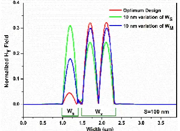
Fig. 10. Normalized Hy field shape along the width axis on the input and output sides of the ADC section with the most idealized and the worst
parameters.
In order to show the effect of fabrication error more clearly, we plotted the shape of the |H𝑦|field at the output sides of
the ADC section with the optimal and the worst parameters in Fig.10. It is clear that most of the power of the input H𝑦11 mode in the SMNW is converted to the H𝑦21 mode in the MMNW efficiently for the optimum design, as shown by a red line. A small residual field in the SMNW is also visible. However, for a possible change in WM by 10 nm, which could
be due to fabrication error, the converted mode profile is shown by a blue line. After that, the converted mode profile is also shown by a green line when WS is changed by 10 nm. It can be observed directly that the performance slightly
[image:10.595.205.392.421.557.2]4. CONCLUSION
A novel OI configuration based on 8-core heterogeneous TA-MCF and a mode splitter using ADC are proposed to overcome the expected capacity crunch in short reach optical transmission system. Through simulations, we have confirmed that deployment of trench layer around each core increases the modal field confinement. It is shown here that the marginal increase in coupling loss can be traded off with drastic XT reduction in heterogeneous TA-MCF OI. Our results also pave the way towards future practical OIs and silicon photonic transceivers.
O
n the other hand, a detailed design optimization of asymmetric directional sections for the fundamental quasi-TE (TM) mode and the higher order quasi-TE (TM) mode (de)multiplexer including the H𝑦21 (H𝑥21), H𝑦31 (H𝑥31), H𝑦41 (H𝑥41), andH𝑦51 (H𝑥51) modes is reported. The accurate width of the MMNW is found by FEM approach. The performance
deterioration due to fabrication errors is discussed in depth by varying key NW parameters, including the widths, separation, and height. A narrow separation should be employed for robust design, which will be less sensitive to the slight fluctuation of the separation, the width of the MMNW, and its height, which may satisfy fabrication tolerance condition of +10nm. The fabrication of SM guide is required to be strictly accurate, which should be less than +5nm. It is also shown that operating bandwidth of the structure is wide enough and suitable for WDM applications. It is also shown here, accuracy of the design must be tested rigorously and if not careful the design may not be viable.
REFERENCES
[1] Taubenblatt, M. A., “Optical interconnects for high–performance computing,” J. Lightwave Technol. 30(4), 448– 457(2012).
[2] Abrate, S., Gaudino, R., Zerna, C., Offenbeck, B., Vinogradov, J., Lambkin, J., and Nocivelli, A., “10Gbps POF ribbon transmission for optical interconnects,” in Proc. IEEE Photonics Conference, 230–231(2011).
[3] Li, M. J., Hoover, B., Nazarov, V. N., and Butler, D. L., “Multicore fiber for optical interconnect applications,” in Proc. 17th OptoElectronics and Communications Conference, 564–565 (2012).
[4] Mishra, J. K., Priye, V., and Rahman, B. M. A., “Error probability performance of a short-reach multicore fiber optical interconnect transmission system,” Opt. Lett. 40(19), 4556–4559 (2015).
[5] Koshiba, M., Saitoh, K., Takenaga, K., and Matsuo, S., “Analytical expression of average power- coupling coefficients for estimating intercore crosstalk in multicore fibers,” IEEE Photon. J.4(5), 1987–1995 (2012). [6] Takenaga, K., Tanigawa, S., Guan, N., Matsuo, S., Saitoh, K., and Koshiba, M., “Reduction of Crosstalk by
Quasi-Homogeneous Solid Multi-Core Fiber,” in Optical Fiber Communication Conference, OWK7 (2010). [7] Saitoh, K., Matsui, T., Sakamoto, T., Koshiba, M., and Tomita, S., “Multi–core hole–assisted fibers for high core
density space division multiplexing,” in Proc. 15th OptoElectronics and Communications Conference,164–165 (2010).
[8] Saitoh, K., Koshiba, M., Takenaga, K., and Matsuo, S., “Crosstalk and core density in uncoupled multicore fibers,” IEEE Photon. Technol. Lett.24(21), 1898–1901 (2012).
[9] Watanabe, K., Saito, T., Imamura, K., and Shiino, M., “Development of fiber bundle type fan-out for multicore fiber,” in Proc. 17th Opto-Electronics and Communications Conference, 475–476 (2012).
[10] Abe, Y., Shikama, K., Yanagi, S. and Takahashi, T., “Physical-contact-type fan-out device for multicore fibre,” Electron. Lett.49(11), 711–712 (2013).
[11] Ding, Y., Ye, F., Peucheret, C., Ou, H., Miyamoto, Y., and Morioka, T., “On-chip grating coupler array on the SOI platform for fan-in/fan-out of MCFs with low insertion loss and crosstalk,” Opt. Express23(3), 3292–3298 (2015).
[12] Tottori, Y., Kobayashi, T. and Watanabe, M., “Low Loss Optical Connection Module for Seven-Core Multicore Fiber and Seven Single-Mode Fibers,” IEEE Photon. Technol. Lett.24(21), 1926–1928 (2012).
[13] Rahman, B. M. A. and Davies, J. B., “Analysis of optical waveguide discontinuities,” J. Lightwave Technol.6(1), 52–57 (1988).
[14] Rahman, B. M. A. and Davies, J. B., “Finite-element solution of integrated optical waveguides,” J. Lightwave Technol.2(5), 682–688 (1984).