Division II
INVESTIGATION OF STRUCTURAL CREEP STRAIN RECOVERY AND
ITS IMPACT ON STRUCTURAL INTEGRITY
Nak-Kyun Cho and Haofeng Chen*
Department of Mechanical & Aerospace Engineering, University of Strathclyde, United Kingdom * Email: [email protected]
ABSTRACT
The creep strain recovery in steels is a material phenomenon of the time-dependent recovery of creep strain after unloading. Effects of the recovery has been commonly neglected or considered insignificant when designing steel components or structures. However, a different mechanism of the structural creep strain recovery, which affects the lifetime of the component, can be identified by non-linear finite element analyses. The aim of this paper is to analyse this structural creep strain recovery mechanism, which can take place under the cyclic thermal and uniaxial tensile loads, and its impact on the structural integrity. It is identified that the mechanism can occur within a peak dwell due to dwell stress relaxations of thermally induced stresses for a certain type of cyclic thermal and mechanical load condition. Further analyses and discussions are provided to investigate the root cause of the mechanism. Various tensile load conditions with a dwell at the peak thermal load are analysed to define factors influencing the structural creep recovery mechanism, and to investigate how the mechanism affects the lifetime of the component. Practical problems and appropriate methods for estimating creep-fatigue damage associated with the mechanism are discussed. From the investigations, it is concluded that the structural creep recovery mechanism during the peak dwell may significantly increases the plastic strain during unloading phase, leading to a creep ratchetting behaviour of the structure.
INTRODUCTION
The power plant industry has many components operating at high temperature creep conditions. In the presence of creep, the response of a structure to cyclic loading changes significantly. The key feature of cyclic loading with creep is the synergistic interaction of cyclic plasticity and creep. Creep strain recovery in steels is a phenomenon of the time-dependent recovery of the creep strain after unloading. This anelastic recovery is attributed to the viscoelastic material property in metals and alloys. However, in general, effects of the recovery has been commonly neglected or considered insignificant when designing steel structures (Bolton 2010). Unlike conventional material related creep recovery, under cyclic thermo-mechanical loading condition, significant creep strain recovery can take place during a single dwell period as well as after the unloading. A phenomenon of the creep strain recovery within the dwell is addressed as the Structural Creep Strain Recovery Mechanism in this paper.
the dwell. As a result, the stress relaxation after being reversed in sign can lead to the creep strain recovery within a dwell.
If a structure experienced this new mechanism, it requires additional attention to the assessment of structural integrity. The compensated creep strain seems to reduce risks of the creep damage, whereas the substantial stress relaxation may cause enhancement in a total strain range. The main objectives of this paper are to analyse the structural creep strain recovery mechanism by comprehensive numerical investigations, and to discuss influence of the mechanism on structural integrity, through a benchmark example of holed plate subjected to cyclic thermal and uniaxial tensile loads with a high temperature creep dwell during the cycle.
PROBLEM DESCRIPTION
Geometry and loading
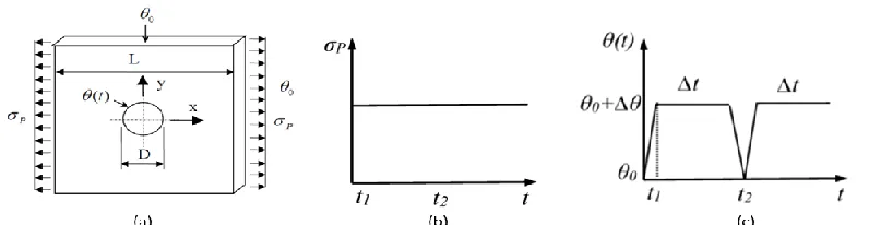
Chen et al. introduced cyclic behaviours of a 3D holed plate with creep effects using a novel numerical method, the extended Direct Steady State Cycle Analysis (eDSCA) method, under the Linear Matching Method Framework (LMMF) (Chen, Chen et al. 2014). The identical 3D model is selected in this paper for analysing the structural response, and geometry of the plate is depicted in Figure 1(a). Ratios between diameter (D) of the hole and length (L) of the plate, and between thickness of the plate and the length (L) are of 0.2 and 0.05, respectively. The combined loading consists of the cyclic thermal load as temperature difference between the hole and the outer surfaces of the plate, and the constant uniaxial tension acting along the horizontal axis. The temperature, θ, varies from θ0, ambient temperature, to θ0+Δθ as a time function and three load instances follow in an order by loading (t1), creep dwell (Δt), and unloading (t2). The applied boundary conditions can be seen in Figure 1(a) and the loading is assumed to have three load instances as illustrated in Figure 1 (b) and (c).
Figure 1. (a) Geometry of the 3D plate and loading condition, (b) uniaxial tensile load, and (c) cyclic thermal load.
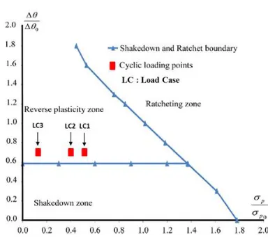
[image:2.612.109.507.405.508.2]Figure 2. Shakedown and ratchet limit curve for the holed plate with the cyclic thermal load and the constant mechanical load without the creep effects.
Finite element model and verification
The detailed cyclic analysis considering full creep-cyclic plasticity interaction is performed using ABAQUS (Abaqus 2012) step-by-step analysis. For a quarter model of the plate with symmetry boundary conditions, twenty-node quadratic hexahedral elements with reduced integrations (C3D20R) are used. Outer surfaces of the plate are constrained by equations in order to maintain the plane condition. The FE meshed model is depicted as Figure 3 (a).
It is assumed the plate is made of the stainless steel 304. An elastic perfectly plastic material is assumed for the plasticity with Young’s modulus (E = 200GPa), temperature independent yield stress (σy = 205MPa), and Poisson’s ratio (ν = 0.3). The yield surface of the perfectly plastic model can be defined by:
0 )
(
J ij y
f
(1)where f is a function of yield surface, J(ij) and ydenote the invariant equivalent stress tensor and
yield stress respectively. For evaluating the creep behaviour, Norton-Bailey law is widely used, which can be defined by:
m n c
t A
(2)where
cdenotes equivalent creep strain rate,
is the effective von-Mises stress, and t is dwell time. A, n, and m are temperature dependent material constants that are generally independent of stress. In this paper, in order to simplify the analysis, following material constants are considered; A = 5.86 x 10⁻¹⁵ at temperature of 500°C, n=5 as a typical value for austenitic steel, and m=0 so the Norton-Bailey law is reduced to the Norton’s law.Figure 3. (a) Meshed FE model and FE model verification; (b) equivalent creep strain for 10hrs dwell time from the LMM and (c) equivalent creep strain for 10hrs dwell time from the SBS analysis.
RESULTS
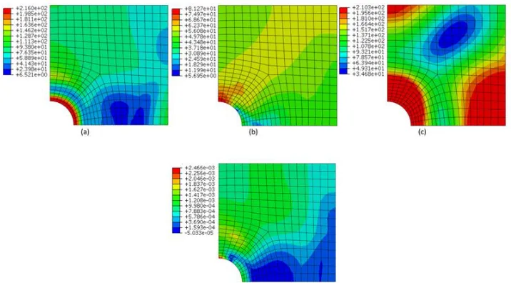
In order to account for the structural creep strain recovery mechanism, a SBS analysis is performed with load case 1 for dwell time of 200hrs. Figure 4 illustrates equivalent von-Mises stress distributions per load instance and equivalent creep strain distributions at creep dwell period at the last cycle. It can be seen that the peak stress value is observed at the top of the hole, in which also appears the peak creep strain increment at the dwell period. To understand the structural response of the plate, an element with the peak stress and the peak creep strain is selected as a point of interest for further investigation.
Figure 4. Equivalent von-Mises stress distribution per loading instance with load case 1 for dwell time
200hrs at the last load cycle; (a) loading, (b) creep, (c) unloading, and (d) equivalent creep strain
increment at dwell
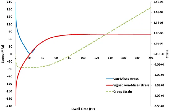
[image:4.612.79.529.68.193.2] [image:4.612.128.486.354.552.2]during the dwell period. For a very early stage of the dwell, the compressive creep strain grows with a compressive creep stress. The growth becomes steady in a range of the creep stress from -50MPa to 40MPa, and afterward the tensile creep strain starts to evolve with a tensile creep stress until the end of dwell time and recovers the previous compressive creep strains.
As mentioned, the new creep recovery phenomenon is caused by the creep stress redistribution at the peak dwell. The redistribution can be explained given that the thermal gradient across the plate and the constant uniaxial load generate compressive secondary stresses and tensile primary stresses respectively at loading as shown in Figure 6. The secondary thermal stress dominates the primary mechanical stress at the beginning of the dwell, but its relaxation causes the primary stress to become the dominant internal stress after the dwell time of 20hrs. After about 100 hours of relaxation of thermal stress, the creep stress becomes a steady state primary stress in the opposite direction to the initial secondary stresses, with a constant increase of the creep strain due to the remaining tensile primary stress as shown in Figure 5. The creep-cyclic plasticity response of the plate is depicted in Figure 7, where ε is strain increment, the subscripting of L, BR, R, U denotes loading, before recovery, recovery, and unloading respectively, and superscripting of e, c, and p denotes elastic, creep, and plastic respectively.
Figure 5. Creep stress relaxation curves and creep strain increment with load case 1 for dwell time 200hrs
[image:5.612.167.442.288.469.2]at the point of interest
Figure 7. Response of steady state stress-strain hysteresis loop corresponding to load case 1 for dwell time
200hrs
From these results, it has been confirmed that the change of the dominant internal stresses during a dwell period can lead to the new creep recovery mechanism. Moreover, it should be noted that the significant stress relaxation develops considerable residual stresses during the dwell, which result in an enhanced evolution of plastic strain at unloading. In order to fully understand the new mechanism, effects of varying load level on the mechanism are analysed in the following parametric study.
PARAMETRIC STUDY
Identical SBS analysis is performed with load case 2 and 3 for dwell time of 200hrs each. In order to evaluate the effects of the dominant stress component σ11, it is reasonable to alter the uniaxial tensile load level only in this parametric study. With respect to the chosen point of interest, key values and features from the FE analyses are summarized in Table 1, where
sand
care the start of dwell stressand the end of dwell stress respectively, tsdenotes the approximated dwell time before creep strain recovery to occur (C.S.R is an abbreviation for the Creep Strain Recovery, and negative signs before the values in the table represent the compressive stress and strain). Hysteresis loops for the three load cases are plotted as seen in Figure 8.
Table 1. Comparison key values and features for different load cases
LC
s(
MPa
)
c(
MPa
)
BRc
Rc
Lp
Up ts C.S.R1 -205 79.94 -6.34E-04 2.88E-03 -6.10E-04 3.10E-03 14 ~ 21 Y
2 -205 63.38 -7.65E-04 4.88E-04 -6.11E-04 2.98E-03 43 ~ 63 Y
[image:6.612.68.529.536.615.2]Figure 8. Response of steady state stress-strain loop corresponding to load cases 1, 2, and 3 for dwell time 200hrs
It can be seen that the end of dwell stress tends to decrease with a decrease of the uniaxial tensile load. In other words, the time period to be dominated by the secondary stresses gets affected by the level of the tensile load. As a result, load cases 2 and 3 develop larger creep strain with the compressive dwell than load case 1 within time of ts. The recovery mechanism also likely appears later at a lower level of the tensile load. On the other hand, due to the shorter time being in creep strain recovery (total dwell time minus time of ts) and lower levels of the end of dwell stress, both the creep strain with the tensile dwell and the plastic strain at unloading are decreased, which result in reducing the total strain range.
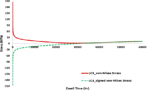
Interestingly, the new mechanism is not shown with load case 3 for the dwell time of 200hrs. This is because the secondary stresses do not relax enough in order for the primary stresses to become the dominant stress within the dwell time. In the theoretical aspect, the thermal stresses can completely relax when the dwell time goes to infinity. In other words, the creep strain recovery mechanism should be able to appear when the primary stresses are imposed against the secondary stresses. To verify this hypothesis, another SBS analysis is performed with load case 3 applied for an extended dwell time of 60,000hrs. The recovery is confirmed by the creep stress history as shown in Figure 9. From this parametric study, it is verified that variations of the tensile load have effects on the time for the recovery to occur, which lead to an increase of the total strain range with the increase of tensile load.
DISCUSSION
Practical problems involving the structural creep strain recovery mechanism
As demonstrated with the FE analysis results, the structural creep strain recoverymechanism can be observed when the significant creep stress redistribution occurs across a structure within a dwell period. In order for the stress relaxation to be reversed in sign, the structure has to be imposed with the internal stresses consisting of the primary and the secondary stresses. The secondary stress has to be larger than the primary as well as acting in the opposite direction. Remarkably, although a structure is imposed with the internal stresses, the stress relaxation may not be significant without a significant high temperature creep. If high temperature structures experience this mechanism in cyclic operations, it is expected to negatively affect the lifetime of the structure with an increased total strain range as shown in the previous hysteresis loops. Therefore, it is worth discussing practical problems, which may have additional potential risks regarding this mechanism.
Components in non-isothermal conditions can be found in forced cooling systems using either air flow or coolant equipment. An internal combustion chamber has mechanical components such as cylinder liner, piston, and valves. These mechanical parts in operation are exposure to very high temperature and high pressure in their cooling system. It has been reported that cracking or excessive plastic deformation including creep are known issues in these components (Fakaruddin, Hafiz et al. 2012). High temperature heat exchangers also have the potential risks, with the thermal gradient between inlet and outlet lines. Thus, steel casings or structures holding tubes or fins are likely vulnerable to thermal fatigue damage considering the mechanism. Moreover, metal matrix composite (MMC) material in the elevated temperature may experience the similar problem. Due to the different coefficients of thermal expansion of the two materials, thermally induced internal stresses can be imposed on edges of the metal matrix phase even at isothermal condition. To avoid the hidden risk, material selection and life assessment of the components are very important.
Creep-fatigue damage calculation method
The cyclic thermo-mechanical load of high temperature can result in creep-cyclic plasticity cycles, which may affect the lifetime of a structure due to creep-fatigue damage. There are several damage calculation methods that are adopted in the high temperature design codes. However, the standard methods may not always give accurate predictions for the damage against variation of the dwells and the stress states within the cycle. Spindler (Spindler 2007) proved the stress modified creep ductility exhaustion method gave better results than the time fraction method and the creep ductility exhaustion method provided respectively in ASME and R5, using test results from three austenitic stainless steels. However, the structural creep strain recovery mechanism allows creep strain accumulations under both compressive and tensile creep stresses within a peak dwell, which has a different type of creep stress relaxation comparing with test results introduced by Spindler. Therefore, it is worth discussing how to evaluate creep-fatigue damage in presence of the new mechanism.
A current method to calculate creep and fatigue damage in R5 is a linear damage summation,Dc Df 1, where
D
cand Df denote creep damage and fatigue damage respectively. Thefatigue damage per cycle,df , in R5 is expressed as:
)
,
(
/
1
N
0T
d
f
T (3)III and the ductility exhaustion (DE) rule and the stress modified (SM) ductility exhaustion approach in R5, defined respectively by:
d t f TF cT
t
dt
d
0
(
,
)
(4)
dt
T
d
d t c f c DEc
0
(
,
)
(5)dt
T
d
d t c f c SMc
0
(
,
,
)
(6)
where
t
dis the dwell time, tfis the creep rupture time which is a function of stress and temperature, andf
is the material creep ductility which is a function of the instantaneous creep strain rate at a given temperature. If function of the ductility including both stress and the strain rate, it is used for the stress modified approach.To evaluate creep-fatigue damage with the new creep strain recovery mechanism, it requires considering the healing effect of compressive dwell (Wells and Sullivan 1969). The sintering of creep cavities under compressive creep may be able to compensate the creep damage cumulated under tensile creep. For the new mechanism, there are three critical dwell time increments to be considered, which are: time for the creep stress being reversed in sign (ts), time for creep strains being fully recovered (tr), and end of dwell time (td).
For dwell time of ts, creep damage in a sign domain needs to be considered using the SM rule, while fatigue damage may have a significant effect within a cycle due to end of dwell stress becoming zero. For dwell time of tr, both tensile and compressive creep stress take place within a single dwell, resulting in physically no creep strain increment. Thus it is suggested that fatigue damage within time of tr is increased while creep damage is negligible. For the time beyond this, from the full recovery time of tr to the end of dwell time td, creep damage now requires consideration along with fatigue damage corresponding to total strain range.
In the case of stress relaxations starting from a compressive stress, it is suggested that creep damage within the time increment from tr to td only needs to be taken into account, and Eq.(3) is applicable to fatigue damage calculation in consideration of the healing effect and a direction of creep-ratchetting heading to tensile. On the contrary, if it is starting from a tensile stress, creep damage needs to be considered only within dwell time of ts, otherwise creep damage within a cycle can be negligible, if the dwell time beyond this. Eq.(3) is still applicable to fatigue damage calculation within dwell time of tr, while, for dwell time of td, it should reflect removal of the nucleation phase by altering
N
0to NginEq.(3) considering a direction of the creep-ratchetting moving to compressive, where Ngis the number of
CONCLUSIONS
1. The structural creep strain recovery mechanism has been identified and investigated by finite element analyses with a 3D centre holed plate under cyclic thermal load and constant uniaxial tensile load within a peak dwell. In presence of the mechanism, both compressive and tensile creep strains will occur within a single dwell period due to a significant secondary stress relaxation.
2. The tensile load level plays an important role in the mechanism. Without the load, the creep stress to be reversed in sign due to the relaxation will not occur during the dwell period. The load has effects on time for the creep strain recovery to occur and magnitude of the end of dwell stress which affects plastic strain range at unloading.
3. Key influencing factors of the mechanism are the internal stresses consisting of the primary and the secondary stresses and the applied creep constants. Potential risks associated with this mechanism could be found within either high temperature components equipped with a forced cooling system or MMC materials that have different coefficients of thermal expansion.
4. With the new creep strain recovery mechanism, it is suggested that creep damage should be reduced or not be taken into account for a single dwell in which either physically zero increment of creep strains or compressive creep strains are larger than tensile creep strain, in consideration of the healing effect. On the contrary, fatigue damage is likely to increase with the substantial creep stress relaxation within a cycle, compared with typical isothermal creep relaxation. In the case where compressive creep strain is dominant in a cycle, it is recommended to use the revised formula for fatigue damage calculation. Consequently, the new mechanism will have negative effects on the structural integrity, leading to a creep-ratchetting response.
REFERENCES
Abaqus, V. (2012). " 6.12-3, User’s manual."
Ainsworth, R. A. and R5_Panel (2014). Assessment procedure for the high temperature response of structures. EDF Energy Nuclear Generation Ltd. 2/3.
Bolton, J. (2010). "The consequences of recovery for the analysis of creep in steel structures." International Journal of Pressure Vessels and Piping 87(5): 266-273.
Chen, H., W. Chen and J. Ure (2014). "A Direct Method on the Evaluation of Cyclic Steady State of Structures With Creep Effect." Journal of Pressure Vessel Technology 136(6): 061404.
Chen, H. and A. R. Ponter (2001). "Shakedown and limit analyses for 3-D structures using the linear matching method." International Journal of Pressure Vessels and Piping 78(6): 443-451.
Fakaruddin, M. A., A. M. Hafiz and K. Karmegam (2012). "MATERIALS SELECTION FOR WET CYLINDER LINER." IOSR Journal of Engineering (IOSRJEN) e-ISSN: 2250-3021.
Manson, S. and G. R. Halford (2009). Fatigue and durability of metals at high temperatures, ASM International.
Spindler, M. (2007). "An improved method for calculation of creep damage during creep–fatigue cycling." Materials Science and Technology 23(12): 1461-1470.