RIT Scholar Works
Theses
3-2014
Folding Seating System for Airports
Xiaoxiao Pu
Follow this and additional works at:
https://scholarworks.rit.edu/theses
This Thesis is brought to you for free and open access by RIT Scholar Works. It has been accepted for inclusion in Theses by an authorized administrator of RIT Scholar Works. For more information, please [email protected].
Recommended Citation
Folding Seating System for Airports
By
Xiaoxiao Pu
MFA
ROCHESTER INSTITUTE
OF TECHNOLOGY
Industrial Design
School of Design
College of Image Art and Science
ACKNOWLEDGEMENTS
I would like to acknowledge and express my gratitude to all those
who have made this thesis project possible.
ABSTRACT
Commercial flight and other fast transport ensure the operation of
today’s busy and fast-paced society. Air travel of today, under its mature
market, still needs to improve its capacity to respond to emergency
situations. A comfortable, safe and quiet place for those who are stuck in
the airport due to an unexpected layover or weather delay should be
one of the improvements of the airlines. The purpose of this thesis was
to design a seating system to help transiting or layover passengers spend
a night at the airport more comfortably and safely based on the existing
seating system.
Approvals
Stan Rickel
, Chief Advisor
Associate Professor
Industrial Design Graduate Director
585-475-4745 /
Signature: ___________________________ Date: __________________
Alan Reddig, Committee Member
Senior lecturer, Industrial Design
585-475-2954 /
Signature: ___________________________ Date: __________________
Amos Scully, Committee Member
Associate Professor, CIAS Foundations
585-475-6747 /
Signature: ___________________________ Date: __________________
Peter Byrne
Associate Professor, Administrative Chair
585-475-2668 /
Table of Contents
1.0 INTRODUCTION ... 5
2.0 INSPIRATION STORY ... 8
3.0 AIRLINE ON-TIME STATISTICS ... 9
3.1 On-Time Arrival Performance Analysis ... 9
3.2 Delay time - Analysis ... 10
3.3 General Terms& Conditions for flights delay ... 11
4.0 EXISTING SEATING PROBLEM ... 12
5.0 EXISTING SEATING SYSTEM RESEARCH ... 14
5.1 Popular seating review ... 14
5.2 Field research at Greater Rochester International Airport ... 16
6.0 FOUR-BAR MECHANISM ... 21
6.1 Four-Bar Mechanism ... 21
6.2 Classification ... 22
7.0 DESIGN FOR EZ FOLD STORE AND SNORE ... 24
7.1 Initial Concept ... 24
7.2 Design for Storage Folding ... 29
7.3 Improved design based on field research ... 35
7.4 Joints and 4 bar mechanism application ... 36
7.5 Basic mechanism test ... 38
7.6 Appearance design ... 42
7.7 Arrangements ... 42
7.8 Final Product ... 43
8.0 PROSPECTIVE USER SCENARIO ... 46
1.0 INTRODUCTION
Fig 1-1 Current Scenario
Commercial flight and other fast transport ensure the operation of today’s busy
and fast-paced society. People fly to different cities to visit friends, meet business
partners, enjoy time with their families or travel the world. Meanwhile, the golden
age of trains is long gone. Along with the accelerated process of social
informatization, rail transport is more suitable for the elderly or people who have
more leisure time. In contrast, for a business person or an average traveler, flight is
the fastest, most convenient and sometimes the cheapest way to deal with business
meetings or enjoy a family trip.
“At least you can get a comfortable sleep on the train” said a passenger with
its mature market, still needs to improve its capacity to respond to emergency
situations. A comfortable, safe and quiet place for those who are stuck in the airport
due to an unexpected layover or weather delay should be one of the improvements
of the airlines. Because of the inaction of most airlines, there even exist websites
such as the one named “The Guide to Sleeping in Airports.” It lists the various
methods to help make sleeping in airports more tolerable. Because of the frequency
of such cases, the development of corresponding rest systems should be considered.
The purpose of this thesis was to design a seating system to help transiting or
layover passengers spend a night at the airport more comfortably and safely based
on the existing seating system. The idea of EZ fold store n snore arose from the need to relieve transiting passengers’ fatigue and help make the passenger waiting area
more comfortable, thus promoting the existing airport system and satisfying their
clients on site. The purpose of a redesigned seating system is to allow people to sleep,
to offer security of luggage, and to provide a place of privacy as much as possible.
EZ fold store n snore is an advanced seating system based on the existing passenger seats set in front of every departure gate. Through transforming the seat
structure, it can complete a shift from seat to bed and back to seat. EZ fold store n
snore integrates a four-bar mechanism, connection joints, a mechanical lock and privacy settings. The entire seating system contains a rotatable back wall, a rotatable
chair arm, two connected pads that can unfold into a bed, and a fixed seat base.
Passengers can have a full night’s sleep or just a nap before they board a flight by
In addition to the above considerations, it was clear that business-class and
first-class passengers are more inclined to choose hotels instead of stretching out on
an airport floor. Some of them take advantage of a VIP room in which to rest, which is
more spacious, holds fewer people, and is of a higher quality in general than other
public area. The purpose of this thesis is not to satisfy this kind of passenger, but to
2.0 INSPIRATION STORY
I was inspired by my personal experience while in transit at Chicago Midway
International Airport. The airline cancelled my connecting flight and changed my seat
to another airline, I needed to reclaim my luggage and then go through the security
system again. However, the flight arrived at the transfer airport at 11:30pm, and the
security area closed at 12:00am, before I retrieved my luggage. As my next flight was
at 6:00am the next morning, I had been told that I couldn’t go through the security
until 4:00am the next morning— a common scenario for international flights. I
therefore decided to spend the night in the waiting area.
However, the nightmare was just beginning. First of all, I felt hungry. Even
though Chicago Midway International Airport is a big airport, there were no shops
open 24 hours at the concourse. The only Starbucks closed at midnight. After I
grabbed a cup of coffee and watched the Starbucks close, I realized that I should find
a place to sleep as soon as possible. Soon, the idea of sleeping had vanished. Every
chair’s arms hindered me and I was unable to squeeze my body into the chair’s space.
After I finally squeezed myself into a chair in a twisted position, the public address
announcement began to surround me, endlessly repeating. Actually I met a worse
situation in the end. I eventually found a warmer, quieter, more secure, and even
larger space: the airport’s restroom. Regardless of cleaning workers using loud
machines every two hours, I kept my luggage with me, covered my jacket, and slept
in a stall in the front of the toilet, which was, at least, a fairly “private space.” I
3.0 AIRLINE ON-TIME STATISTICS
Based on the situation that happened to me, I did relevant research to confirm
the actual delayed data for all U.S. airlines. The results of the study are surprising.
Contrary to what most people think, the number of delayed flights reached about
265 per day (see in the analysis). Even assuming that all of the planes are the
smallest planes, averaging 150 to 200 seats, a total of 45,000 people could face the
same situation as me, needing to re-plan their schedule and sometimes needing to
find somewhere to spend the night, often in an unfamiliar place.
3.1
On-Time Arrival Perf ormance Analysis
Fig. 3-1-1 On-Time Arrival Performance (BTS)
According to data from The U.S Department of Transportation’s (DOT) Bureau
of Transportation Statistics (BTS), 18.52% of flights were delayed from February 2012
National Aviation System delay; security delay; and aircraft arriving late, being
cancelled or being diverted. Air carrier delay, National Aviation System delay and
aircraft arriving late were the top three most frequent reasons, accounting for more
than 83% of delays. Human factors affected delay more than natural factors and
there was less than 0.5% delay because of weather. (See Fig. 3-1-1)
3.2
Delay time - Analysis
Fig. 3-2-1 Histograms of departure and arrival delays
Besides the data of the reasons for delays, the length of delay time directly
affects passengers’ activity after they are informed of the flight delay. As we can see
from the two bar charts in Fig. 3-2-1, only 5% of flights were delayed more than three
hours or delayed overnight. However, in consideration of the total number of flights
every day, which is 28,537 according to the National Air Traffic Controllers
Association, the amount still is a large number. About 265 flights per day were
3.3
General Terms& Conditions for flights delay
According to Federal Aviation Administration (FAA) regulations, a flight is
considered to be delayed when it is 15 minutes later than its scheduled time. When
flights are canceled or delayed, passengers may be entitled to compensation due to
rules that must be adhered to by every Flight Company, usually Rule 240 or Rule 218
in certain locations. This rule usually specifies that passengers may be entitled to
certain reimbursements, including a free room if the next flight is the day after the
canceled one, a choice of reimbursement, rerouting, phone calls, and refreshments.
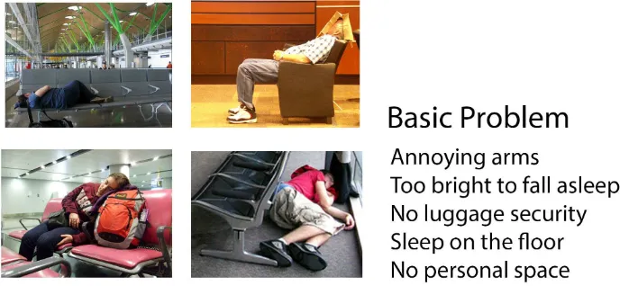
4.0 EXISTING SEATING PROBLEM
Fig. 4-1 Analysis of existing seating problem
According to this frequent scenario at the airport, I summarized the following
reasons for embarking on this thesis project. (See Fig. 4-1) First of all, annoying chair
arms are the biggest obstacle to providing a comfortable surface on which to rest or
sleep. Chair arms may provide a more private space when people sit next to each
other, but for those passengers who want to take a nap, they cannot spread out their
bodies through these arms.
Having no place to secure luggage is another important issue. If there is no
enclosed space to lock luggage, passengers actually cannot fall into a deep sleep.
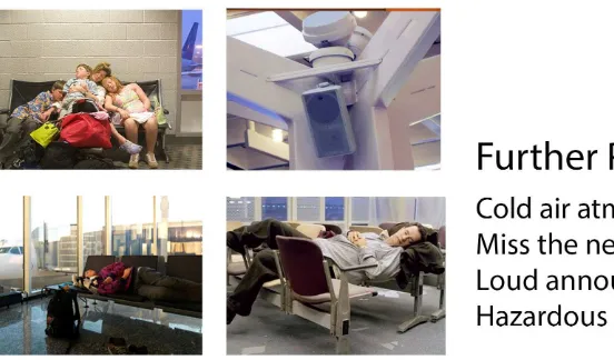
Fig. 4-2 Analysis of existing seating problem
Beyond that, bright lighting, a cold air atmosphere, loud announcements and
no personal space are other minor problems (See Fig. 4-2). These factors all affect
people getting a good rest at the airport.
In fact, airports sometime will supply some simple cots for delayed
passengers sometimes. However, the amounts available are not substantial. Women
and children will get them first and others just sleep on the floor or try to keep a
position on the seat like the above picture shows in the bottom right corner in Fig.
5.0 EXISTING SEATING SYSTEM RESEARCH
5.1
Popular seating review
At this stage, I researched online to sort out four typical and advanced existing
public seats that were used at the airport. Some of them provide a more comfortable
environment for passengers. Below are examples of the seats produced by four
different companies around the world.
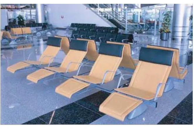
[image:16.612.141.472.363.583.2]Matteograssi
Fig. 5-1-1 Matteograssi spa
The Italian company Matteograssi is a former saddle-making company known
for adding innovation and quality to the waiting area seat industry. It is a few
companies to offer a back chair and seats with full body support. (See Fig. 5-1-1)
leather cushions, the chair meets a high level of public seating standard. The
disadvantage of the seat is that every part is fixed and need larger space than in
usual.
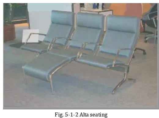
Alta
Fig. 5-1-2 Alta seating
Alta is another Italian company. Alta seating is modern and generally creates
contemporary designs. They have a full-body seating system on the market. (See Fig.
5-1-2)
[image:17.612.173.433.181.374.2]Pacifica
Pacifica is the most ergonomic and durable of the inexpensive seating
produced by an America company – Airport Seating Alliance. The seating system is
highly adaptable, with elements such as end tables and armrests easily added. (See
Fig. 5-1-3)
Herman Miller (Eames chair)
Fig. 5-1-4 Eames chair by Herman Miller
Herman Miller is a major American manufacturer of office furniture,
equipment and home furnishings. It is likely the most prolific and influential producer
of furniture in the modernist style. This seat contains two identical pads for the back
and seat, which lead to an easier assembly and replacement process. Meanwhile, the
two sides of the pad are the same as each other, so they can be used as a temporary
replacement when they need to change it. (See Fig. 5-1-4)
5.2
Field research at Greater Rochester International Airport
In addition to the online research, I did a more visualized and precise research
the dimensions for the average seats at the airport.
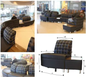
Fig. 5-2-1 Seat in the waiting room
For the passengers’ family member or friends who are picking up a passenger, a
waiting room is used in most cases. Therefore, the seats in the waiting room are
more comfortable than the usual waiting seats, large and could be several rolls of
sofa.
The length of the longest sofa shown in Fig.5-2-1 is 84 inches. The height of this
sofa is 28 inches, comprised of 13 inches for the back of the seat and 15 inches for
the seats, which is as high as the smaller single sofa on the opposite side. The single
sofa is 28.5 inches wide. (See Fig. 5-2-1)
Fig. 5-2-2 Seat in the waiting room
Another sofa at the west side of the waiting room, which has a broader field of
inches high. (See Fig. 5-2-2)
Fig. 5-2-3 Seat at luggage claim
Unlike the seats at the waiting area, the seats in the luggage claim area are
designed for a shorter seating time. Therefore, these seats are less comfortable, with
smaller dimensions, and face the luggage machine.
The seat shown in Fig. 5-2-3 is the most minimalist seat in the luggage claim
area. It is 73 inches long, 31 inches high and 17 inches deep. (See Fig. 5-2-3)
Fig. 5-2-4 Seat at luggage claim
Another public seat at luggage claim is shown in Fig. 5-2-4. The dimensions of
this kind of seat are the same as a regular office chair. The dimensions are 31 inches
Fig. 5-2-5 Seats outside the security checkpoint
The seats outside the security checkpoint have a snake shape as seen in Fig.
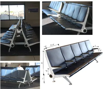
Fig. 5-2-6 Seats in the front of the boarding gate
In terms of the general gate seats, the height from the top of the chair back to
the top of the seat is 23 inches. The height from the seat to the floor is 17 inches.
And the distance between the arms and the top of the seat is 7.5 inches. Each
separate chair is 23 inches wide (including the 1.25 inches wide frame) (See Fig.
5-2-6).
CONCLUSION
The general height of the seats ranges from 28 inches to 33 inches. The width
of the seats is from 21 inches to 28 inches. And the depth range is 17 inches to 19
6.0 FOUR-BAR MECHANISM
[image:23.612.115.342.167.471.2]6.1
Four-Bar Mechanism
Fig. 6-1-1 Parallel movement
The basic definition of the four-bar mechanism:
A four-bar linkage, also called a four-bar, is the simplest movable closed
chain linkage. It consists of four bodies, called bars or links, connected in a
loop by four joints. Generally, the joints are configured so the links move in
parallel planes, and the assembly is called a planar four-bar linkage. [2] (See
Fig. 6-1-1) However, if one of the two equal bars is shortened, the whole
system will no longer move in parallel, but in an elliptical movement within a
mechanism.
6.2
Classification
The movement of a quadrilateral linkage can be classified into eight cases on
the dimensions of its four links. Let a, b, g and h denotes the lengths of the input
crank, the output crank, the ground link and floating link, respectively. Then, we can
construct the three terms:
T1 = g + h – a – b, T2 = b + g – a – h, T3 = b + h – a – g.
The movement of a quadrilateral linkage can be classified into eight types
based on the positive and negative values for these three terms, T1, T2, and T3. [3]
T
1T
2T
3 Grashof condition Input link Output link-
-
+
Grashof Crank Crank+
+
+
Grashof Crank Rocker+
-
-
Grashof Rocker Crank-
+
-
Grashof Rocker Rocker-
-
-
Non- Grashof 0- Rocker 0- Rocker-
+
+
Non- Grashof ππππ- Rocker ππππ- Rocker+
-
-
Non- Grashof ππππ- Rocker 0- Rocker+
+
-
Non- Grashof 0- Rocker ππππ- RockerThe cases of T1 = 0, T2= 0, and T3= 0 are interesting because the linkages fold. If
we distinguish folding quadrilateral linkage, then there are 27 different cases.
The figure shows examples of the various cases for a planar quadrilateral
linkage. [4]
Fig 6-2-2 Types of four-bar linkages, s=shortest link, l=longest link
The configuration of a quadrilateral linkage may be classified into three types:
convex, concave, and crossing. In the convex and concave cases no two links cross
over each other. In the crossing linkage two links cross over each other. In the convex
case all four internal angles are less than 180 degrees, and in the concave
configuration one internal angle is greater than 180 degrees. There exists a simple
geometrical relationship between the lengths of the two diagonals of the
quadrilateral. For convex and crossing linkages, the length of the one diagonal
increases while the other one decreases. On the other hand, for non-convex
non-crossing linkages, the opposite is the case: one diagonal increases if and only if
7.0 DESIGN FOR EZ FOLD STORE AND SNORE
7.1
Initial Concept
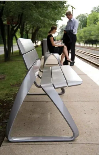
Public seats commonly appear in parks, on streets, in commercial districts and
in other public places. Among public seating, the airport is one of the small branches.
When I was thinking about airport public seating design, on the basis of connectivity
of public seating, I realized I should take into account other special requirements for
transit passengers and especially the transit passenger who is delayed.
Fig. 7-1-1 Public Seating
As mentioned in the introduction, airplane passengers in business class and
first class have more advanced seats (See Fig.7-1-2). These convertible seats provide
a 135-degree elevation for passengers. The whole system relies on an electric drive
[image:26.612.220.392.292.561.2]comfortable angle. However, complex mechanisms and huge expense are two
prerequisites of those seats. It is obviously not suitable for my design.
Fig. 7-1-2 first-class seats
Therefore, when I thought about my thesis direction, the seat had to have
functions for both sitting and sleeping, rely on a dynamic mechanism, and provide a
more comfortable environment for delayed or layover passengers.
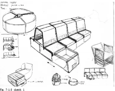
[image:27.612.215.398.131.272.2]Fig. 7-1-3 sketch 1
[image:27.612.111.501.358.666.2]turn over, stack, rotate, etc. All of them add new characteristics based on the
dimensions of current public seats (See Fig. 5-2-6). The security of luggage storage
was taken into consideration in my design as well. This point in particular captured
the mind of one of my professors. As my original thesis direction was slightly
different, after the professor helped me determine this direction, I started to detail
[image:28.612.112.513.255.530.2]ideas.
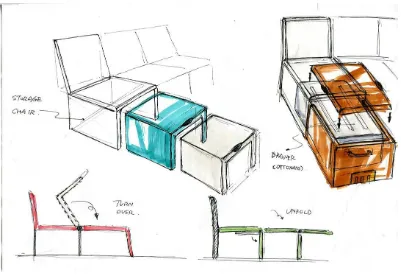
Fig. 7-1-4 sketch 2
At the beginning, I refined the practical ways of implementing different initial
ideas (See Fig. 7-1-4). The sketch shown in the top left corner is a nested chair.
Usually, every smaller sub-chair nests together to save space. And when you take
them out, a bed-like sleeper seat comes out. The ideas shown in the images on the
transform from a seat to a bed. For the idea in the top right corner, I thought more
[image:29.612.130.477.141.433.2]about the necessary details for luggage security.
Fig. 7-1-5 sketch 3
This sofa storage idea (See Fig. 7-1-5) creates the best of both worlds: the inner
sofa block stays inside of the chair when not in use and pulls out to be a sleeper sofa
with secured luggage. However, the cost is too high if we produce all the seats to be
sofas.
After brainstorming, I realized the carry-on luggage size restrictions influenced
the luggage space needed inside of the chair. According toDelta, American Airlines,
7-1-6)
Fig. 7-1-6 Carry-on Luggage size restrictions
Based on these restrictions, I came up with one more concept (See Fig. 7-1-7).
Through two scalable steel trims, the seat pad can easily slide from an obtuse angle
into a plane. In this design, a strong enough support for a steel structure could be
considered.
[image:30.612.138.472.438.692.2]7.2
Design for Storage Folding
After several attempts, I found that folding is the best way to take full
advantage of space. Therefore, at this stage, I researched several different ways of
folding chairs.
Fig. 7-2-1 Hypnos chair bed designed by Alfredo Häberli
Scandinavian design always shows simplicity. The first example, in Fig. 7-2-1,
shows a Hypnos chair bed with a flipped seat pad combined with two steel arms.
Through a simple flip, two arms suddenly becomes to two stands. After that, you can
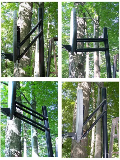
Fig. 7-2-2 Metal Murphy bed
The second example (See Fig. 7-2-2) shows the well-known Murphy bed. This
company owns a patent for a simply but effective metal structure that can be easily
controlled, with the angle changed from vertical to horizontal, and the mattress pad
fallen down with the metal structure subsequently.
Murphy beds are used for space-saving purposes, much like trundle beds, and
are popular where floor space is limited, such as small homes, apartments, hotels,
mobile homes and college dormitories. [6]
Compared to the other previous methods, the folding chair or seat obviously
occupies the most important position in all transformable furniture.
7.2.1
Two seats to be one bed
Fig. 7-2-3 Paper model 1
I used a paper model to explore possible folding methods, especially aimed at
public seating rather than personal seating. (See Fig. 7-2-3) Later, I found that if we
attempt to extend the length of one side of the seat, the better way is to make use of
the length of the other side such as by straightening the whole panel to be a plane.
Fig. 7-2-4 Paper model 2
However, in the real world a wood board cannot be easily folded like paper. So
people must add hinges to each of the joints. Meanwhile, when every joint is folded
as in the “Fold state” shown in Fig. 7-2-5, the highest point must have enough
strength to support the entire body. All of these factors increased the difficulty of the
[image:34.612.111.502.67.358.2]production.
In addition, people must find a way to pull the whole piece of wood out,
acknowledging that the weight of two chair surfaces can be heavy. And how to fix
movable sides of the board in both the “Fold State” and the “Unfold State” was
another big issue. In this case, moving two seats to become one bed may lack
practicality.
[image:35.612.111.507.303.602.2]7.2.2
One seat to one bed
Fig. 7-2-6 Paper model 3
This model used the same as Alfredo Häberli did (See Fig. 7-2-6). By flipping the
Fig. 7-2-7 Paper model4
Based on the essence of the way to reverse the front pad of the seat, I came up
with another way to reverse the back pad of the seat. Fig. 7-2-8 shows the schematic
process of the seat. Step 1: turn the back from vertical to horizontal; step 2: flip over
the upper seat pad; step 3: move two seat pads to the front following the sliding
[image:36.612.112.489.71.355.2]action—and the seat becomes a bed.
However, in this concept, the upper pad with arms needs to provide both
surfaces to be sitting in both the “Fold State” and the “Unfold State”. This increases
the production cost and complicates the process.
7.3
Improved design based on field research
Fig. 7-3-1 Schematic process improved seat
Combined with the field research data, I found out the most appropriate
distribution dimensions of each part of the seat. If the force bearing point is 18
inches lower than the top of the back, then the back of the seat could be 15 inches
long with half pad long of the medium pad B (See Fig. 7-3-1) to be the top of the
storage box in the “Unfold state”. The entire seat is 72 inches long, equal to 6 feet,
when it is opened.
In this improved model, I changed the direction of turning of both A and B-C, so
that the entire flip could be smoother. I was not concerned about the usability of
whether in fold or unfold state. Besides, after the change, the complex sliding action
on the sides of the seat was eliminated. This also simplifies the seat system.
After that, I proceeded to figure out the mechanism and connect the joints of
the entire seat system.
7.4
Joints and 4 bar mechanism application
Because I eliminated the sliding action, I needed to limit the scope of the
angle of pad A and hold steady on pad B-C whenever they are closed as 0 degree or
[image:38.612.209.448.382.664.2]opened to 180 degrees.
Fig. 7-4-1 shows four key joints used in my design. Pictures A and B are the
detailed drawings of the connection part of pads B and C. This special hinge allows
those two pads to open in one direction. Picture C shows the axe connecting pad C
and the seat frame. I also used the same joint to connect pad B with its arms. Picture
D is the four-bar mechanism mentioned before, which is used to connect the seat
[image:39.612.133.482.272.484.2]back A and the seat frame.
Fig. 7-4-2 Four-bar mechanism for parallel
After learning about the four-bar mechanism, I figured out the precise length
from the joint to the corner of each pad frame based on the previous seat
dimensions. The whole system provides a space from 24 inches long at fold status to
72 inches long at the unfold state. Fig. 7-4-2 clearly shows the changing of the space.
7.5
Basic mechanism test
At the beginning of the test, I could find a way to figure out the right place in
each “bar.” My professor gave me a good method to measure the distance from the
connect point to the end of the bar by using a 2-D model of the side view of the seat
rather than try to figure out all the dimensions using a 3-D model directly.
[image:40.612.110.472.287.502.2]1. 2-D four-bar mechanism test
Fig. 7-5-1 2D four-bar mechanism test
In fact, all main dimensions can be projected onto the side view as Fig. 7-5-1
shows in the design. The back of the bottom box, the back pad of the seat, and the
two bars connected to these two parts make up the four-bar mechanism. This
mechanism admits a movement from 120 degrees to 180 degrees. At the same time,
the front pads open from 195 degrees to 0 degree. The two pads meet each other
The material I used to do the test was a piece of medium density foam, a
piece of white paper and a couple of round-head fasteners. Fasteners are helpful in
rotating and relocating several bars on the paper. Every time I found the connection
in the end was not continuous, then I pulled out the fasteners and moved to another
possible point to try again.
2.
3-D Model test
Fig. 7-5-2 3D model test (fold)
material as it can be made into any shape I want by sanding. It is gratifying that the
3-D was very successful and able to complete the movement from fold to unfold.
However, as you see in the figure, because of the thickness of the model, I was
[image:42.612.111.504.183.481.2]unable to glue the backside of the box onto the front side of the box. (See Fig. 7-5-3)
Fig. 7-5-3 3D model test (unfold)
Due to the accuracy of the model making, I did not get a precise model or
dimensions of each part statement unclear and antithetical. Therefore, I finally
thought about using SolidWorks to build a computer model for testing purposes.
3.
SolidWorks Model Test
In the SolidWorks model, I typed in similar dimensions as the result of a mock-up
other in order to follow the movement.
Fig. 7-5-4 Screenshot of the animation of SolidWorks model
As the front part of the seat moved forward and the back part flipped to the
horizontal, those two pieces of pads seamless connected to each other again (See Fig.
7-5-4). During the movement, the arms stayed in the side of the pad. I had hoped the
arms would flip over to serve as the stand in the next step.
Fig. 7-5-5 Screenshot of the Animation of SolidWorks model
[image:43.612.179.440.485.676.2]Fig. 7-5-5). The animation can be found at the following URL:
https://xpxdesign.squarespace.com/thesis-folding-seating-system-for-airports
[image:44.612.114.503.170.386.2]7.6
Appearance design
Fig. 7-6-1 Appearance design
When I thought about the appearance of the seat, I hoped it would be concise
and have a sense of science and technology rather than merely exhibit complex
mechanical structures. Therefore, I tried to integrate every part and covered under
the one-piece of plastic shell. I discovered that if I wanted to retain the cuboid base
to storage luggage, then the appearance would be very heavy. Therefore, I tried to
make maximum use of space and get rid of redundant parts of the base box. The
sketch in the middle of the bottom is the final direction of the design. (See Fig. 7-6-1)
7.7
Arrangements
Once the usability and cost of the seat system was taken into consideration, I
consideration of personal privacy, every alternate seat can be opened to a bed. At the
same time, in regard to reducing costs, the arrangement solved the problem of total
deployment. Although people still need to walk in a zigzag pattern when they travel
through the passageway due to the limit length between two rolls in general, it is
[image:45.612.200.413.242.563.2]good for people to have a place to rest that is not physically close to others.
Fig. 7-7-1 Seats arrangement
7.8
Final Product
After detailed research, understanding of the mechanism, reasonable
product in the end.
Fig. 7-8-1 Final model (single)
EZ fold store n snore includes six pieces: a back pad of the seat (connected to both the front side and the back side of the base box), one piece comprising the arms
(attached to the front seat pads and locked to the back pad), two front seat pads
connected to each other (attached to the front side of the base box), a base box, and
seat stands (attached to the base box). When using the chair, the first step is to lift up
the arms, then flip over the two front pads to horizontal. Second, put the arm on the
ground so that the two pads can be rigid. Finally, flip over the back pad to become
horizontal. Also, if people need to put their luggage in the box, they can slide it in
before the pads deploy totally. Based on the location and direction of the front
opening, if someone sleeps on the bed, no one can get their luggage without waking
Fig. 7-8-2 Final model (rows)
For the entire system, the requirement of personal privacy and a dark
environment for sleeping passengers was taken into consideration, so the top roof
between the two rows is fixed when using the chair. Therefore, when someone is
sleeping on a chair, they can hide their head. An alarm system including screen
display and corresponding light underneath the roof could alert passengers in time
for their next flight. (See Fig. 7-8-3)
8.0 PROSPECTIVE USER SCENARIO
Fig. 8-1 Presentation of User Scenario
In the prospective user scenario, it is 2020. Serena is about to fly to Las Vegas,
when she hears an announcement that the flight will be delayed until the next
morning. Later, she feels tired and bored but has nothing to do while waiting. With
midnight approaching, airport personnel come to open the seat for her and tell her
she can sleep on the EZ fold chairs. She is surprised, and has a good night on the chair. The next morning, after with the soothing music of the sweet morning wake-up call,
she closes the bed, transforming it back into a seat, and gets on the plane on time.
List of References
Books:
1. Hanna Julia, Improving Fairness in Flight Delays, August 31, 2011.
2. Hartenberg, R.S & J. Denavit, Kinematic synthesis of linkages, 1964, New York
3. J.M.McCarthy and G.S. Soh, Geometric Design of Linkages, 2nd Edition, Springer
2010
4. Robert L. Norton, Design of Machinery 3/e, May 2, 2003, ISBN 0-07-247046-1
6. Melamed Samantha, Hidden beds springing out if woodwork, January 12, 2013
Articles:
5. Toussaint, G.T., “Simple proofs of a geometric property of four-bar linkages”,