Rochester Institute of Technology
RIT Scholar Works
Theses
Thesis/Dissertation Collections
8-1-2002
Fiber reinforced composites of a novel pendent
polyimide: Optimum processing and mechanical
properties
Akshay Kamdar
Follow this and additional works at:
http://scholarworks.rit.edu/theses
This Thesis is brought to you for free and open access by the Thesis/Dissertation Collections at RIT Scholar Works. It has been accepted for inclusion in Theses by an authorized administrator of RIT Scholar Works. For more information, please [email protected].
Recommended Citation
Fiber
Reinforced
Composites
of a
Novel
Pendent
Polyimide:
Optimum
Processing
and
Mechanical Properties
A Thesis
Presented
to
The Graduate
Faculty
ofRochester Institute
ofTechnology
In
partialfulfillment
Of
the
requirementsfor
theDegree
ofMaster
ofScience in Materials
Science
andEngineering
Akshay
R
Kamdar
Fiber Reinforced Composites of a Novel Pendent
Polyimide: Optimum Processing and Mechanical Properties
Akshay R Kamdar
Approved:
Dr. Marvin
L.
IIIingsworth
(Advisor)
Dept. of Chemistry
Accepted:
Dr.
K.S.V. Santhanam
Interim Department Chair
Copyright Release Form
Fiber Reinforced Composites of a Novel Pendent
Polyimide: Optimum Processing and Mechanical Properties
I, Akshay R. Kamdar, hereby grant permission to Wallace Memorial Library of
the Rochester Institute of Technology, to reproduce my thesis in whole or in part. Any
reproduction will not be for commercial use or profit.
Date:
~-
02 -
02
ABSTRACT
A
2-component
polyimide [3,4'-ODA +4,4'-ODPA],
a 3-component"parent"
polyimide
[3,4'-ODA
+4,4'-ODPA+ 10 mol% Mellitic aciddianhydride (MADA)]
and a4-component
"pendent"polyimide [3,4'-ODA+ 4,4'-ODPA + 10 mol % MADA + 10
mol %
Zr]
were synthesized and characterized using fourier transform infraredspectroscopy
(FTIR),
differential scanning calorimetry(DSC)
and thermogravimetricanalysis
(TGA)
techniques. Sincetemperatureandtime arecriticalfactorsinfluencing
the thermal and mechanical properties ofthefinal
polyimide, itis
important tohave detailedinformation
onthebest time-temperature conditions for imidization and cure in ordertooptimize the processing and properties of this polyimide. The present investigation
focused
ondeveloping
these conditions for the polymer. The processing condition ofheating
the poly(amic acid) at 310 C for 15 minutes was chosen as an optimumprocessing condition for the Zr-pendent polyimide. The sample showed complete
imidizationwithoutany decompositionatthegivenprocessingtemperature.
The polyimide resins were also investigated as a matrix for high performance
composites. Prepregs were fabricated using the conventional
hand
lay-up
technique.Carbonand/or glass fiberreinforced composite laminateswere
fabricated
in an autoclaveto obtain a 60:40 fiber to resin
by
weight ratio.Tensile,
flexural,
Izodimpact
anddynamic mechanical analysis tests were carried out on the composite laminates.
Mechanical properties ofthe pendent polymer were compared with those ofthe parent
(withoutpendent groups)polyimide. Failuremechanismswere studiedthrough theuse of
optical andscanning electron microscopy. The Zr-pendentpolyimide composites showed
lower moduli for the mechanical tests performed as compared to the
2-component
andparent polyimide composites. Comparisons of mechanical datawith
laminates fabricated
ACKNOWLEDGEMENTS
"If
an experiment works, something hasgonewrong"
Finagle 's First Law. Dr.
Illingsworth
certainlyhelped
me prove him wrong through his valuable suggestions,continuous encouragement and extremepatience,especiallywhentheresearch struggled.
This thesis would not
have
been a success without the constant support and valuableinsights
of my committee members, Dr.Langner,
Dr. Angela at XeroxCorporation
and Dr. Carle from the MechanicalEngineering
Technology
Department.Special
thanks toDr. Kimforhelping
meduring
theinitialphasesofmythesis.I would like to thank Owens
Corning
and Mr. John Alexion at Composites One forthesupplyofglass and carbon fibers. I appreciatethe effortsofthestaff attheCenterfor
Composite Materials at theUniversity
of Delaware forfabricating
the composite samples and that ofDie Max ofRochester for cutting them. I also thankTom Locke at the Center for IntegratedManufacturing
Studies(CIMS)
for hishelp
in making notchesin the composite samples. Sincere thanks to Dr. Michael Jackson andPeter Terrana for their
help
withtheSEMatthemicroelectronicsdepartment.I am grateful to the Material Sciences and
Engineering
department and theChemistry
department for awarding mewith aTeaching
Assistantship. To Tom Allstonand the stock room staff, your constant support made all thehurdles so easy to
jump.
Iwould liketo say a special "thank you"
to Brenda Mastrangelo for always cheering me up.
To my lab co-workers, Wei
Cheng
and Sangeetafortheirhelp,
andto myfriends,
Prakash, Vivek, Eugene, Abhishek,
Ashish, Mayank, Suruchi,
Hrishikesh andRajiv,
this thesiswouldnothave beensomuchfunwithout yourhelp
andwittycomments.Writing
this thesis would not have been sointeresting
withoutlistening
to the tunesofDire Straits andPink Floyd.And last butneverthe
least,
to myparents andfamily
forloving
me so much andTABLE OF CONTENTS
Page
ABSTRACT
iiiACKNOWLEDGEMENTS
ivTABLE OF
CONTENTS
vLIST OF TABLES vii
LISTOF FIGURES ix
CHAPTER
I. INTRODUCTION& BACKGROUND
1.1. Introduction 1
1.2.Background 8c
Theory
31.2.1 Polyimides Overview 3
1.2.2Properties & ApplicationsofPolyimides 7
1.2.3 Fiber Reinforced Polymer Composites 8
1.2.4 FabricationofComposites 10
1.2.5Failure Mechanisms in Composites 12
1.2.6 OverviewofResearch PolyimidesunderInvestigation 14
1.3. Hypothesis 16
1.4. Major Objectivesofthis
Study
16II. EXPERIMENTAL
2.1 Chemicals andMaterials 18
2.2 Synthesis of
2-,
3- and4-Component Poly(amicacid)s 19 2.3Establishing
OptimumProcessing
Conditions
242.4CharacterizationTechniques 25
2.5 FabricationofComposite Laminates 26
IH.
RESULTS
AND DISCUSSION3.1
Synthesis
of2-,
3- and4-Component Poly(amicacid)s 35 3.2Establishing
OptimumProcessing
Conditions 373.2.1 Visible Color Changes 37
3.2.2 Fourier Transform Infrared
Spectroscopy
(FTIR)
373.2.3 Thermogravimetric Analysis
(TGA)
443.2.4 Differential
Scanning Calorimetry
(DSC)
52 3.2.5 Summary: DeterminationofOptimumProcessing
Conditionand
Molding
Cycle 543.3 Composite Fabricationand
Processing
553.4 Mechanical PropertiesofLaminates 59
3.4.1 Tensile Test (ASTM
D3039/D3039M-95a)
593.4.2 Izod Impact Test (ASTM
D256-00)
733.4.3 Flexural Test (Three-point
bending)
(ASTMD790-00)
84 3.4.4 Dynamic Mechanical Analysis(DMA)
(ASTM D4065-95)....94 3.4.5Summary
oftheComparisonofMechanical PropertiesofLaminates Fabricated using Different
Molding
Cycles 1013.4.6
Summary
(GlobalDiscussion)
103IV. CONCLUSIONS 105
V. FUTURE WORK 107
LIST OF TABLES
Table
Page1 1
Chemical
structures ofadditionpolyimides 61.2 Propertiesof selectedconventional andcompositematerials 8
2. 1 Fabric
Specifications
182.2
Heating
stepsforthepoly(amicacid) powder 242.3 Autoclaveparameters 29
2.4 Tensiletestparameters(ASTM D3039/D3039
M-95a)
312.5 Flexuraltestparameters(ASTM
D790-00)
323.1 Infraredabsorptionbandsof
imides
373.2 % Degreeofimidization forthe2-componentpolyimideresin 43
3.3 % Degreeof
imidization
fortheparent polyimide resin 433.4 % Degreeof
imidization
forthependentpolyimide resin 443.5 Comparisonof actual andtheoreticalweightusing different processing
conditions 50
3.6 Weightloss
(%)
ofthe threeresinsheldat370 C foronehour 513.7a Glasstransitionsobserved
in
the2-componentpolyimides 543.7b Glasstransitionsobservedintheparentpolyimides 54
3.8 Resincontent of compositelaminates using Method 1 57
3.9 Resincontent ofcomposite laminates using Method II 58
3.10 Tensiletestfor 2-componentcarbonfiberreinforced composite 60
3.11 Tensiletest for 3-componentcarbon
fiber
reinforced composite 613.12 Tensiletestfor 4-componentcarbon
fiber
reinforced composite 613.14
Prepregand
autoclavefabricationparameters 663.15a
Comparison
oftensilestrength andmoduli of2- and3-componentcomposite
laminates
from different moldingcycles 663.1 5b
Comparison
oftensilestrength andmoduli of4-componentcompositelaminates from
different moldingcycles 673.16 Impactstrength and resistance forthe2-componentcarbonfiber
composites 74
3.17 Impactstrengths and resistanceforthe3-componentcarbonfiber
composite 75
3.18 Impactstrengths and resistanceforthe4-componentcarbonfiber
composite 75
3.19 Comparisonofimpactstrength and moduliof
2-,
3- & 4-component compositelaminates fromdifferent
moldingcycles 773.20 Flexuralstrengths and modulusofthe2-componentcarbonfiber
composites 85
3.21 Flexuralstrengths and modulus ofthe3-componentcarbon
composites 86
3.22 Flexuralstrengths andmodulusofthe4-componentcarbon
composites 86
3.23 Comparisonofflexural strengthandmoduliof
2-,
3- & 4-component compositelaminates from different moldingcycles 883.24 Storagemodulus
(E')
comparison at300 C for different moldingcycles 1 00
3.25 Comparisonof mechanicalpropertiesoflaminates
fabricated
usingLIST
OF
FIGURES
Figure
Page1.1 Kaptoncoveronsolar panelinthe
spaceship
"Discovery"
1
1.2 Atomicoxygen resistance exhibited
by
polyimides with zirconiumcomponents 2
1.3 Chemicalstructureofanimide group 4
1.4 Formationofpoly(amicacid) 4
1.5 Conversion frompoly(amicacid)topolyimide 5
1.6 Chemical structures of
different
polyimides 151.7 Usetemperatures forresin matrixcomposites 9
1.8 Autoclave 11
1.9 Typical vacuum
bag
assembly 122.1 Synthesisofpoly(amic acid)of 3,4'- ODA/ 4,4'-ODPA 19
2.2 ConversionofMellitic AcidtoMellitic Acid Dianhydride 20
2.3 Synthesisofpoly(amic acid)of3,4'-ODA / 4,4'-ODPA/ 10mol%
MADA 21
2.4 Synthesisof
Zr(adsp)(dsp)
Co-polyimide 233.1 TGAgraph ofMADA 35
3.2 Melliticacidand
its
products 363.3 FTERspectrafor 2-componentpolyimide 39
3.4 FTJJR.spectraof parentpolyimides 40
3.5 FTIRspectra ofpendentpolyimides 41
3.6 Isolatedreference peaksobserved at 1012 cm"1
forthe
different
3.7
TGA
curves of poly(amic acid)softhe threedifferentresins 453.8a
TGAcurves of2-component
polymer 463.8b
TGAcurvesof2-component
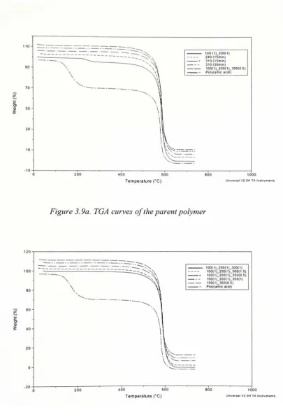
polymer 463.9a TGAcurves oftheparent polymer 47
3.9b TGAcurvesoftheparent polymer 47
3.10a TGAcurves ofthependent polymer 48
3. 1 Ob TGAcurves ofthependent polymer 48
3.11 TGAgraph ofthependent poly(amicacid) 49
3.12 Emulationofmoldingcyclesfortheneat polymer resins. TGAof
2-,
3-,
and4-componentpolyimidesafterheating
at370 C for 1 hourunder
N2
gas 513.13
(a-f)
DSCcurves forthe2-componentpolyimide resin 533.14
Molding
cycleforcompositelaminate fabrication 563.15 Comparisonoftensilestrength oflaminas 63
3.16 Comparisonoftensilemodulus oflaminas 63
3.17 Stress-Straincurvesfor 2-componentcarbonreinforcedtensile
laminas 64
3.18 Stress-Straincurvesfor 3-componentcarbon reinforcedtensile
laminas 64
3.19 Stress-Straincurves for 4-componentcarbonreinforcedtensile
laminas 65
3.20 Stress-Straincurves for 4-componentglass reinforcedtensile
laminas 65
3.21 Tensiletestopticalimagesof2-componentcarbon
fabric
laminas 68
3.22 Tensiletestopticalimagesof
3-component
carbonfabric
3.23
Tensile
testopticalimages
of4-componentcarbonand glass fabriclaminas
703.24 SEM
images
offailedtensile specimens 713.25 SEM
images
offailed
tensilespecimens 723.26 Comparisonof average
impact
resistance(energy)
of carbonfiberlaminates 76
3.27
Comparison
of averageimpactstrengthsof carbonfiber laminates 773.28 Izod
impact
optical imagesof2-componentcarbonfabric laminates 793.29 Izodimpactoptical
images
of3-componentcarbonfabric laminates 803.30 Izodimpactoptical
images
of4-componentcarbonfabric laminates 813.3 1 Izod
impact
opticalimagesof4-componentcarbonfabric laminates 823.32 SEM imagesoffailed impactspecimen 83
3.33 SEMimageof an aluminum foilon aplysurface 84
3.34 Comparisonof averageflexuralmodulusofcarbonfiber
laminates 87
3.35 Comparisonof averageflexural strengthsofcarbon fiber
laminates 87
3.36 Flexuraltestopticalimagesof2-componentcarbon fabric
laminates 89
3.37 Flexuraltestopticalimagesof3-componentcarbonfabric
laminates 90
3.38 Flexural testoptical imagesof4-componentcarbon
fabric
laminates 91
3.39 Flexuraltestopticalimagesof4-componentcarbon
fabric
laminates 92
3.40 SEM imagesoffailed flexural specimen 93
3.42 DMAcurves forparentpolyimidecarbonfiber laminates 96
3.43
DMAcurvesfor
pendent polyimidecarbonfiber laminates 973.44 DMAcurves forpendentpolyimideglassfiber laminates 97
3.45
Summary
oftheDMAanalysis forthedifferentcompositelaminates(a)
Storage Modulus Vs Temperature 99(b)
Loss Modulus Vs Temperature 99(c)
Tan D Vs Temperature 1003.46
Summary
ofcommonlyobservedfailure
mechanisms forthecarbonCHAPTER I
INTRODUCTION &
BACKGROUND
1.1 Introduction
Fiber reinforced polymer composites are considered to be an important class of engineering materials offering unique
flexibility
in design capabilities. The advantages arehighspecific strengths andmoduli, strengthtoweight ratio andfatigue strength.They
are used in many diverse applications in the aerospace, electronics and automotiveindustries.
Currently,
a majority of aerospace applications rely upon compositeshaving
epoxy, bismaleimide or polyimide polymer matrices reinforcedwith one ofanumber of high performance carbon or aramid fibers. The choice of polymer matrix depends primarily on
its
long-term use temperature and the service environment inwhich it will be used. In low earth orbit(LEO),
atomic oxygen(AO)
is themost dominant species at altitudes between 200 and 700 km. As spacecraft orbit the earth at these altitudes,they
collide with atomic oxygen and due to their high orbital velocity, these collisions are energetic enoughtobreakchemicalbonds and oxidize materials. Thisdegradationresults notonly inmassloss butalso areductioninmechanicalandthermalproperties.A DuPont polyimide,
Kapton,
has been chosen for a variety of applications aboardspacecraftin low earth orbit(LEO),
such asthe InternationalSpace Station (ISS). Its characteristicfeaturesareits lowdensity,
highflexibility
and goodthermalstability.However,
the oxidation rate ofKaptonin LEO
atomic oxygen environmentis
great enoughthatstructural
failure
ofthepart occursin
muchlesstimethan theoperatinglife
of the spacecraft. The novel polymer underinvestigation is
a zirconium pendentpolyimide
based
on3,4'-oxydianiline
(3,4'-ODA)
and 4,4'-oxydiphthalic anhydride(4,4'-ODPA).
Films
havedemonstrated
excellent resistance to atomic oxygen(AO)
by
forming
Zr02,
a white powder that acts a protective layer [2]. A schematic diagramrepresenting
theprocess ofZr02
formation has beenshownin Figure 1.2.atomic
m,
*polymeffirr itoninn-iii-rj\7t\
;-jZJ Zroxl*,
/M
|
..,.. [image:16.529.112.433.73.426.2]reformsrjAiii.i layer ot pent
Figure 1.2. Atomicoxygenresistanceexhibited
by
polyimideswith zirconiumcomponentsThe onset ofimidization forthis polymeroccurs at
C,
the glass transitiontemperature
is
-296C
and the thermo-oxidative decomposition temperature of thispolymer
in
airis-551C
[3]. The high glasstransitionanddecomposition
temperatures,
coupledwithits
improved AOresistance,makethisnovel polymer astrong candidateforuse as astructural material aboardtheISS.
However,
theproperties ofthisnovel polymeras acomposite material forstructural applicationshavenot yet
been
investigated.
When polyimides are
thermally
imidized and cured for use either as compositematrix resins or as photoresists and dielectrics in electronic
integrated
circuits,temperature and time become critical factors that
influence
the thermal and mechanicalonthe
best time-temperature
conditionsfor imidization
and cure inorderto optimize theprocessing
andproperties ofthispolyimide. Itis
critical todevelop
an understandingof the role of thermal parameters such asimidization temperature,
glass transitiontemperature and cure temperature at thepartiallyor
fully
imidized
and cured stages andtheir effect on the
final
mechanical properties and adhesion [4]. Since the optimizedprocessing conditions
for
thisnovel polymeris
notknown,
thepresent investigationwillfocus
ondeveloping
theseconditionsforthepolymer.1.2
Background &
Theory
1.2.1 Polyimides Overview
Polyimides are a sophisticated
family
of materialshaving
applications inhighly
technicalend use fields fromaerospacetomicroelectronics. Their
diversity
is
suchthatit leads theminto
applications as adhesives,films, foams,
plastic moldings and resinmatricesfor composites. Theirmajoradvantage, ahighresistanceto
heat,
placesthem ina niche other polymers cannotenter
[5,
6].They
are consideredspecialtyplasticsbecauseoftheir outstanding high performance engineering properties. As such,
they
are pricedwell above the commodity polymers such as polyethylene and polystyrene.
Many
monomers used to prepare polyimides are also specialty chemicals.
Therefore,
thepriceofcommercial polyimidescoversa widerange,
$
8.80-$
1 1 1.00perkg
[7].Synthesis ofPolyimides
Polyimides,
prepared from a variety ofdianhydride anddiamine
monomers, arecharacterized
by
repeating imide structural units in the polymerbackbone
as seenin
Figure 1.3. Thisstructure contributesto theexceptionalthermal and oxidative stabilityofo
II
-CN R"\/\/\y\^
Figure 1.3 Chemicalstructureofan imide group
1.2.1.1 Linear
Condensation
PolyimidesThereare threemaintypesof polyimides:
(1)
Linearcondensationpolyimides,(2)
Thermoplastic polyimides, and(3)
Addition polyimides [12]. Linear condensationpolyimides are prepared from a
two-step
method. In thefirst
step, an aromaticdianhydride
combineswith an aromaticdiamine
inthepresenceof a polarsolventtoforma poly(amic acid).Anexample
is
presentedin Figure 1.4.H,N
Pyromelliticaciddianhydride
r\
/
4,4'-Oxydianiline NH,
NMP/DMAc
O II c
HOOC
\
/ru~\
r*
COOH
Poly(amic acid)
Figure 1.4. Formation ofpoly(amicacid)
In the second step, the
imide
groupis formed
by
a ring closing mechanisminvolving
cyclodehydration of the poly(amic acid). Thisis
achievedby
a thermalimidization
processby
extendedheating
at elevated temperatures of250 - 400 C orby
treatment with chemicaldehydrating
agents. The latter methodis
generally not usedcommercially because
oftheproblems associated withhandling
thereagents. Imidizationinvolves
the release ofby-products
such as water and the loss of residual solvents orvolatiles. The thermal
imidization
step is usually precededby
a processing operation,whereby a poly(amic acid) solution
is
used to cast afilm,
coating or spin a fiber. Thepolymer
in its different forms
is driedandthensubjectedto specificheating
cycles.HOOC
\J~0-\
/-H
COOH
Heat
-H,0
/
Poly(amicacid)
O
II
c
/N^\
/r^w
/
KaptonPoly(imide)
Figure 1.5. Conversion frompolyfamicacid) topolyimide
Polyimides synthesized forthisresearch work followthe condensation technique
described above.
Commercially
availableKapton
(DuPont)
and LARC-IA(Langley
Research Center- Improved
Adhesive)
madeby
NASA are examples of condensationpolyimides.
Polyimides that are generally soluble
in
organic solvents are often preparedby
aone-step or single-stage method. This method is especially useful
in
the polymerization of unreactivedianhydrides anddiamines and canyield a material with ahigher degree
of1.2. 1.2
Thermoplastic
polyimidesThermoplastic
polyimides are obtainedby
introducing
large cyclic side groupsinto
the polymer chain,by
tailoring
random sequencesinto
thechain, or
by
theinterposition
offlexible,
aliphaticlinking
groups betweenthe aromatic and heterocyclicmoieties.
One
generaldrawback
ofthermoplastic polyimidesis
that for use at elevatedtemperatures,
their glass transition temperatures mustbe high (> 200C)
andhencetheirprocessing
temperatures must be evenhigher.
Ultem,
producedby
GeneralElectric,
is
an example of acommercially
availablethermoplasticpolyimide.1.2.1.3 Addition
Polyimides
Addition polyimides usually consist ofshort chain preimidized oligomers with
reactive end groups thatcan react
by
addition polymerization. The end groups usedhave been norbornene, maleimide, acetylenic, allynadic and benzocyclobutene. PMR-15(Polymerization of Monomer
Reactants),
developedby
NASALangley
is
the most widely used polyimide madeby
this technique. Other resins include thebismaleimides,
V-CAP[8],
PMR-11,
LARC-13and LARC-160systems.Table 1.1. Chemicalstructures ofadditionpolyimides*
Trade Name Chemical Structure
PMR-15 BTDE/NE/DDM [diesterofbenzophenonetetracarboxylicacid +
monoesterof nadic acid +
4,4'-diaminodiphenylmethane]
LARC-13 BTDA/NA/3,3'-DDM [benzophenonetetracarboxylic
dinahydride
+nadicanhydride+
3,3'-diaminodiphenylmefhane]
PMR-11 HFDE/NE/PPD [hexafluoropropenedianhydride+ monoester of nadic
acid +p-phenylenediamine
LARC-160 BTDE/NE/AP22[diesterofbenzophenonetetracarboxylic acid +
Monoesterofnadic acid +Jeffamine
22]
*Formoreinformation,refertoWinters, W.; Cavano, PJJO"'
Nat.SAMPETech.Conf., 10(1978)661;T.L. St.Clair;
Progar, D.J.,24,hNat. SAMPESymp.,24(1979)1081andT.L. St.Clair; Jewell, R.A.,23rd
Nat.SAMPESymp.
Characterization
ofpolyimidesPolyimides
canbe
characterized using several techniquesincluding
analytical,thermal,
rheological and mechanical. Analytical techniques such as gel permeationchromatography
(GPC)
anddilute
solution viscometryhave
been used to determine the molecular weight of poly(amic acid)s. Verification of the polymer structure andmonitoring
of the polyimideformation
during
cure canbe
accomplished using FourierTransform
Infrared
(FTfR)
Spectroscopy.
Thermal techniquesinvolving
thermogravimetric analysis(TGA),
thermal mechanical analysis(TMA)
and differentialscanning
calorimetry
(DSC)
allow measurement of thermal decompositions and glass transition temperatures. Rheological properties provide information regarding the flowcharacteristics ofthe resin and
help
to define processing windows forfabricating
fiberreinforced composites. Mechanical and electrical properties are usually obtained
by
casting and curing of poly(amic acid)
films
and performing the desired tests.Tensile,
impact
and tear strength are some of the common mechanical tests while dielectricconstant,
dielectric
strength and volume resistivity are the common electrical tests performed on polyimidefilms.1.2.2
Properties
andApplications
ofPolyimides
The thermal and oxidative stabilities of polyimides are primarily
determined
by
the structural features ofthe polymer. Polyimides derived from aromatic diamines andaromatic dianhydrides exhibit outstanding thermal stability atelevated temperature. The
Tg
determines the method of processing and the maximum temperature at which apolymer can
be
used in any given application. The high glass transition temperatures offeredby
these polymers areattributedto their stiff molecularbackbones,
which containaromatic rings
[6,
7]. Polyimides exhibit good solvent resistance to acidic or neutralaqueous environments.
However,
almost all polyimides undergohydrolytic degradation
in
the presence of strong alkaline aqueous solutions. Their outstanding mechanicalproperties make them excellent candidates in highperformance applications. Like most
bearings,
grinding
wheels and communicators in electric motors. Polyimide films areused as
high
temperatureinsulation
materials and passivation layersin
integrated circuits[7].
They
are also used as resin matrices in advanced composites and as photo resists andinter level dielectrics in
integrated
circuitsin
themicroelectronicindustry.
1.2.3 Fiber Reinforced Polymer Composites
A
judicious
selection offiber,
matrix andinterface
conditions can lead to acomposite with a combination of strength and modulus comparabletoorbetterthanthose
ofmany conventional metallic materials.
Composites
are superior to metals in specificstrength and specific stiffness. Table 1.2 shows a comparison between selected
conventional and composites materials.
Table 1.2 Properties ofselected conventional and composite materials
[9]
MaterialDensity
(P),
g/cm3
Tensile
Modulus
(E),
GPa
Tensile
Strength
(a),
MPaE/p
106N.m /
kg
dip 103N.m/
kg
A16061-T6 2.70 68.90 310.00 25.70 115.00
Ti-6A1-4V 4.43 110.00 1171.00 25.30 26.40
Nylon6/6 1.14 2.00 70.00 1.75 61.40
Unidirectionalhigh
strength carbon
fiber/epoxy
1.55 137.80 1550.00 88.90 1000.00
Unidirectional
E-glass
fiber/epoxy
1.85 39.30 965.00 21.20 522.00
Randomglass
fiber/epoxy
1.55 8.50 110.00 5.48 71.00
1.2.3.1 ResinMatrices
The role ofthe resin matrix is primarily to bind the
fibers
together andhence it
determines the thermal stability ofthe composite. The resinkeeps the
fiber in
adesiredlocation andorientation andacts as aload transfermediumbetween
fibers.
Itprotectsthefiber
from environmental damagebefore,
during
and after composite processing. Thechief polymers used in high performance composites are
thermosetting
resins. TheseThe field
ofthermally
stableheteroaromatic
polymersis
dominatedby
thepolyimides.
Most recently
theiruse as resin matriceshas
attracted the greatest attention.The
needs of thedefense
industry
and thehigh
temperature requirements of theelectronics
industry
have
promoted the use of polyimide coatings,films
and laminates.The most
commonly
used polyimide resin matrices for composites are condensationpolyimides,polymerizationof monomer reactants
(PMR)
andbismaleimides
(BMI)
[9].It is the
outstanding
thermal stability and relative ease offabrication that haveestablished the reputation of polyimides as viable
engineering
materials andparticularlyas resin matrices foradvanced composites. Figure 1.7 showstheusetemperature forresin
matrix composites.
600
SHORT TIME (SECS)
LONG TIME (HRS)
EPOXY BISUALEIUOE POcnuoE
Figure 1. 7. Usetemperaturesforresin matrix composites
[10]
Until now, epoxy based composites were the most
important
matrix materials.However,
their long-term useis
limited to temperatures up to 130 C.Bismaleimide
(BMI)
resins offer a"half wayhouse"
intemperatureperformances
between
epoxies andpolyimides. The reason for the intense interest in BMI systems is their ability to be
fabricated using epoxy-like conditions and without the evolution of
void-producing
volatiles. BMI systems are capable ofperforming at temperatures up to 230 C
[10].
Service temperatures for polyimides depend on the application requirements. For
polyimides
have
shownto exhibit good short-term andlong-term
performanceoverlargetemperatureranges.
1.2.3.2 Fiber
Reinforcements
Fibers aretheprincipal load
bearing
membersinacomposite.They
areusuallyofhigh
strength and modulus and areincorporated into
the matrix either in continuouslengths
or as choppedfibers.
Examples offiber
reinforcements areglass, carbon, aramid,boron,
alumina, silicon carbide and polyethylene fibers. Even though these fibers have high tensile moduli,they
are usually brittle (have low elongation), with carbon fibersmore
brittle
than aramid or glassfibers.
1.2.4
Fabrication of
Composites
Thetechniquesmostcommonlyusedforthefabricationof composites are[1 1]:
1)
ManualLay-Up
(WetLay-Up
andPrepreg Method)
2)
Automated Tape Lamination3)
VacuumBag Molding
4)
AutoclaveCuring
5)
FilamentWinding
6)
Pultrusion7)
Matched-DieMolding
8)
ResinTransferMolding (RTM)
and9) Spray-Up
MethodsPrepregs fortheresearch work were madeusing themanualwet
lay-up
techniqueandcomposites were then fabricated
by
autoclave curing. These techniques have beendescribed below:
1.2.4.1
Prepreg
FabricationA prepreg
is
a fiberreinforcement that has beenimpregnated
with resin, slightlyprepregstoproduce
laminates depends
uponthe typeofpolyimideusedforimpregnation,
theequipment
(autoclave
orpress),andtheshape oftheitemandits
thickness [12].There
are two primary varieties of fiber reinforcement, unidirectionalfibers
(tapes)
and wovenfabrics.
These fiber
assemblies areimpregnated
either via solutioncoatingprocedures or
by
hot
melt methods. Recentwork hasalso shownthatprepregcanbe produced
by
powderimpregnation
andby
the co-mingling offibers. In the hot-meltmethod, resin
is
rolledinto
a thinfilm
ofdesired
thickness to provide the correctfiber/resin
ratio. The reinforcement and resinfilm
are thenjoined and passed betweenheated
rollersto saturatethebundlesoffibers
producing aprepreg. In solventcoating, thefibers
(usually
a wovenfabric)
are passedthroughbaths containinga solution oftheresinin a solvent. Thepreimpregnated
fabric
is thenpassed through aheated ovento removemost ofthe solvent. The prepreg is rolled at the end ofthe line with a release paper
interleaf [10].
1.2.4.2 Autoclave
Curing
The technique most often used in the lamination of carbon or graphite fiber
reinforced composites is the autoclaveprocessing (See Figure 1.8). It is alarge pressure
vessel equipped with a temperature and pressure control system. The elevatedpressures
and
temperatures,
required for processing ofthelaminate,
are commonly achievedby
electrically
heating
apressurized inertgas such as nitrogento reduceoxidizingreactionsthatoccurintheresinatelevatedtemperatures. Pressureappliedintheautoclave provides
force to consolidate the plies and to compress vaporbubbles to obtain a product with
minimum voidcontent.
The
first
stepinvolved
in
this processis
the vacuum bagging. The startingmaterial
is
normally aprepreg, whichis
then laid up as plies on a moldsurface. Thisis
followed
by
the placement of a porous releasefilm
and ableeder material. The porousrelease
film
permits the excess resinto flowthrough,
while thebleedermaterial absorbsthe excess resin. This stack
is
then covered with abarrierfilm,
abreather material and aheat resistant vacuum bag. The barrier material prevents the resin from clogging the
breather and vacuum lines whereas the breathermaterial acts as adistributor for airand
escapingvolatiles and gases. The entire assembly is thenplacedinside the autoclave and
a vacuum
is
applied withinthebagging
film to achieve a uniform pressure and to drawout volatiles created
during
cure. Figure 1.9 shows a typical vacuumbag
assembly[9,
11].
VACUUMLINE
CJUr/.VALVE SAGGING TilM
BHEATHKR
[image:26.529.50.464.22.453.2]SEALANT
Figure 1.9. Typicalvacuum
bag
assembly[11]
However,
the above hand lay-up/autoclave fabrication type ofprocessing is notonly costly but also environmentally unfriendly. NASA is currently
developing
anautomated robotictowplacement
technology
thatcould overcomethesedeficiencies [14].1.2.5
Failure Mechanisms in Composites
Failurebehaviorofcompositesis complexduetotheiranisotropic nature. It
is
notonlythe magnitudeofthe stressesthatare
important,
butalso theorientation ofthemainstresses relativeto the axes ofthematerial's anisotropy. Compositepolymers can
have
anumber of fiber orientations i.e. continuous, discontinuous or randomly oriented. The
undergo. For unidirectional, continuous
fiber
composites, the
direction
ofthe externallyapplied stress
largely
determines
thefailure
mode of thecomposite.
However,
in
laminates,
comprised of a number of plies withvarying orientations, the
failure
modeis
theresult of a complex
interaction
offactors.
Themechanical responsetoloading
is
oftenreferredtoas
being
eitherfiber
or matrixdominated.
Thetypicalcompositefailuremodesare
described
below [15]:
1)
Debonding
Debonding
is due
tointerfacial failure
along thefiber-matrix boundary.
Thisis
characterized
by
thefracture
surfaceshowing
numerousprotruding
fibers
withlittle
ornoresin
adhering
to them.2)
Interlaminar
FailureInter laminar
failure
can occur when theinterfacial
strength between matrix andfibers is
greater than the matrix cohesive strength. Such failure is manifestedin
thecompositeexhibiting excessively brittle behavior.
3)
FiberBuckling
Fiber
buckling
can occurin
compressionwhenthematrixhas inadequate
strength.Micro
buckling
offibers is
a common form offailure
in the case ofcontinuousfiber
reinforced composites subjected to compression. This failure has also
been found
tooccur as a result ofcuring at high temperatures when there is a significant
difference
betweenthedegreeofcontraction ofthematrix andthe
fibers.
4)
Fiber PullOutFiberpulloutarisesduetovariationsinthe
interfacial bond
strength andlocalized
load
transferfromthefiberto thematrix.The energydissipated
during
fiber
pull outfromthe matrix
is
largely
dependant inthedegree ofinterfacialfriction
present, whichinturn5)
FiberBreakage
Fiber
breakage has been
regarded as asignificant energy absorbingmechanisminthe
failure
ofcompositematerials.6)
Cracking
ofComposites
Cracking
in
composites canbeinitiated
by debonding
atthefiberresininterface.This can result
in
a transverse ply crack thatincreases in
length,
and upon reaching afiber
continues alongit
andthenproceedsbackinto
thematrix. This phenomenon,wherea
propagating
crackin
thematrix canbe deflectedanumber oftimeswhenit impingesonthe
fiber
reinforcementis called crackdeflection. Thiscrackdeflectionphenomenon is animportant
mechanism inincreasing
the toughness of the polymer matrix, since thefracture
pathlength ismuchless readilyachieved.7)
Micro crackingMicro cracking ofcontinuous fiber composites is induced
by
thermal expansionmismatchesbetween the fiber andthematrix causingconsiderable stresses andthese can
result incomplete yielding ofthematrix.
Furthermore,
macroscopic thermalmismatchescan also occurbetween cross plies.
Cross-ply
laminates generatehigher residual stressesthan unidirectional laminates because ofthe anisotropy in the thermal expansion ofthe
plies.
1.2.6
Overview
of
Research Polyimides
underInvestigation
Three different types ofpolyimides have been synthesized forthisresearchwork
by
thecondensationtechniquedescribedabove:1)
2-componentpolyimidebasedon3,4'-ODAand4,4'-ODPA2)
3-component"parent"polyimidebasedon3,4'-ODA,
4,4'-ODPAand 10mol%
Mellitic Acid Dianhydride
(MADA)
to form a copolymer of(3,4'-ODA
+4,4'-ODPA)
&
(3,4'-ODA + MADA). MADA acts as a site for pendent groupattachmentand,
3)
4-component"pendent"
MADA and 10 mol
%
zirconium pendent group to form a copolymer of(3,4'-ODA
+4,4'-ODPA)
&
(3,4'-ODA + MADA + Zr). The Zr-pendent groupis
attached atthe site oftheMADA.
Figure 1.6shows comparisonswith respecttochemicalstructures madebetween
thependent polyimide andcommerciallyavailableKapton& andLARC-IA.
/
Vo^ \
DuPont Kapton
NASA-LARC-IA
^tX^-oJ^o^
CVr^o.,,
H.
W
,H C:N N:CZirconium-pendentpolyimide
Asseen
from
Figure1.6,
Kaptonhas
one etherlinkage
whileNASA'sLARC-IA polymerhas
two etherlinkages
alongthepolymer chain.Thisimparts
a certain degreeof mobility to the polymerbackbone.
The novel research polymer also has two etherlinkages in
90%
ofits
monomer groups(whichareidentical
toLARC-IA),
but duetotheheavy
zirconium pendentgroup attachedin
theremaining
monomers,its
mobilitymay be somewhatdiminished.
The
2-component
polyimide synthesized inthepresentresearch is verysimilarto theLARC-IA developed
by
NASA. LARC-IAis
prepared from 3,4'-ODA and 4,4'-ODPAin
NMP as a 30 %w/w solids solution andthemolecularweight is controlledby
endcapping groups such as phthalic anhydride(PA)
whilethe2-componentpolyimideis
preparedfrom3,4'-ODA
and4,4'-ODPA in NMP as a 15%
w/wsolids solution without anyendcappinggroups.1.3 Hypothesis
Since the pendent group structure is massive relative to the mass of the repeat units ofthepolymerchain,mobilityofthechain shouldbe
hindered,
which shouldmake the resin stiffer and more brittle. It is hypothesized that the moduli for a variety of mechanical properties will be lower for composites with pendent polymer as the resin matrix as compared to those with parent (without pendent groups) polymer as the resin matrix.1.4
Major Objectives of
thisStudy
There aretwo objectives defined forthis present study. In the
first
objective, theaim
is
toidentify
the processing conditions that produce the maximum degree of imidization in the shortest time possible. This would potentially beimportant
toprocessing industries usingpolyimides, as there wouldbe optimumproduct performance andshortercycletimes to manufacturetheproduct
leading
tohigherproduction rates. To achievethis,
optimum processing conditions forthe 2-componentpolyimide(3,4'-ODA
+
4,4'-ODPA),
3-component "parent" polyimide (3,4'-ODA +4,4'-ODPA
+ 10 mol%
4,4'-ODPA + 10 mol
%
MADA + 10 mol%
zirconium complex) will be establishedby
varyingthe timeandtemperatureparameters of aprogrammable oven.The second objective
is
to fabricate woven carbon or glass fabric reinforcedcomposites of the
2-,
3- and 4-component polyimide and evaluate their mechanicalproperties
for
structural applications. Comparisons ofmechanical data with laminatesChapter
II
EXPERIMENTAL
2.1
Chemicals
andMaterials
3,4'-Oxydianiline
(3,4'-ODA)
(TCI,
Tokyo)
and 4,4'-Oxydiphthalic anhydride(4,4'-ODPA)
(ChrisKev
Company, Inc.)
were purifiedby
sublimingthree times at84 C
and 254
C,
respectively. These chemicals were then stored in a dessicator containingP2O5
to prevent moisture absorption. Thel-methyl-2-pyrollidinone
(NMP)
(AldrichChemical
Co.)
was driedby
distillation
overCaH2
just prior to its use.Benzenehexacarboxylic
acid (mellitic acid) was obtained from TCL Tokyo. Thezirconium(IV) n-butoxide
[Zr-(0-n-Bu)4]
anddicyclohexylcarbodiimide
(DCC)
wereobtained from Aldrich and used as received. ER grade potassium bromide
(KBr)
forinfrared
spectroscopic analysis was acquiredfrom
Aldrich Chemical Co.Carbon fabric
(Hexcel Style282)
was received fromComposites
One. Glassfabric
(Corning
StyleWR24-5X4C)
was obtained from OwensCorning,
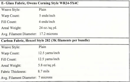
Inc. Other [image:32.529.46.488.398.675.2]relevant properties are presentedin Table 2.1.
Table 2.1. Fabric Specifications
E- Glass
Fabric,
OwensCorning
Style WR24-5X4CWeave Style: Plain
Warp
Count: 5 ends/inchFillCount: 4 ends/inch
Areal Weight: 24 oz./sq.yd.
Avg. Filament Diameter: 17.2 microns
Carbon
Fabric,
Hexcel Style 282 (3K filamentsperbundle)
Weave Style: Plain
Warp
Count: 12.5 yarns/inchFill Count: 12.5 yarns/inch
Areal Weight: 5.8 oz/sq.yd.
Fabric Thickness 8.7mils
2.2 Synthesis
of
2-,
3- and4-Component Polyfamic
acid)s
2.2.1
Synthesis
of2-component
poly(amicacid)basedon3,4'- ODAand4,4'-ODPAA 15 weight % solid solution ofpoly(amic acid) using a 1:1 mole ratio of
3,4'-ODA:
4,4'-ODPA
was achieved.Triply
sublimed4,4'-ODPA,
27.3433 g (88.1473 mmol)was added to 106 mL ofNMP
in
a 1000 mLroundbottom flask. The reactionflaskwascapped with a rubber septum and stirred for half an hour and the temperature was
maintained at0
C
using anice-water
bath. A steady flowof nitrogen was maintained inthereaction
flask.
A solution of17.6506 g (88.1472 mmol)oftriply
sublimed 3,4'-ODAdissolved
in 65 mL ofNMP was then added dropwise into the flask using a 10 mLsyringe.
NMP,
75 mL,was used torinse
the flask and syringe. Upongradual addition ofthe
3,4'-ODA,
the4,4'-ODPA dissolved in thesolution and ultimately yieldedaviscous,homogeneous solution. The poly(amic acid) was then kept in a cold room and the
solution was continuouslystirred overnight. The structures forthisreaction are shownin
Figure 2.1.
\ H.N '
P * lx
NMP,0C
r\
\
/"A_
3,4'-ODA
HOOCv^vs^<Kv^v^CO<
O-OttU
^rd
Poly(amic acid)of3,4-ODA / 4,4-ODPA
Figure 2. 1. Synthesis of
Poly
(amicacid)of 3,4'- ODA/ 4,4 '-ODPA2.2.2SynthesisofMelliticAcidDianhydride
(MADA)
Mellitic acid dianhydride
(MADA)
is
a light brown solid prepared from thecyclodehydrationofmellitic acid. Themellitic acidwas heated
in
anitrogen atmosphereat 190-195
acid (~ 1 1 g) was placed ina20mLtest tubecovered with a rubberstopper. The testtube
was then
laid
horizontally
in
adrying
pistol sealedby
another rubber stopper. Thethermometer,
nitrogeninlet
and outlettubes passthroughboththe innerandouterrubber stoppers. The sample was rotatedperiodically
to achieve uniformheating
ofthe melliticacid
by
turning
the outer rubber stopper, which inturnrotates theinner stopperand thusultimately
rotating
theinner
tube. The change in chemical structure which occurs isshown
in
Figure 2.2.COOH
HOOC
HOOC
COOH
COOH
COOH
0 COOH 0
II
II
.c. ,c
(-2H20)
o
1^ ^^^"
A (-190"C)
\^
^^^^
c c
II
II
0 COOH 0
Mellitic Acid Mellitic Acid Dianhydride
Figure 2.2. Conversion ofMelliticacidtoMellitic Acid Dianhydride
One mole mellitic acid loses 2 moles of waterto form MADA. The purityofthe
MADA has been confirmed
by
the TGA analysis that shows a one-step weight loss of5.88
% due
to the loss of 1 mole of water per mole MADAforming
mellitic acidtrianhydride(MATA).
2.2.3 Synthesis of3-componentpoly(amicacid) basedon
3,4'-ODA,
4,4'-ODPA & 10mol
%
MADASynthesis of the 3-component poly(amic acid)
is
similar to the 2-componentpoly(amicacid) exceptthatinthis case, theMADAand4,4'-ODPAwere addedtogether
to thereactionflask. Amole ratio of1.0:0.9:0.1 of3,4'-ODA: 4,4'-ODPA: MADAwitha
15 weight
%
solid solution was achieved. A total volume of 750 mL solution ofpoly(amic acid) was prepared for processing evaluation, preparation of prepregs and
O o C00H
0 0 NH2
&"
Jo
4,4'-ODPA 3'4'-DA COOH
NMP,0C MADA
COOH
O O -9x HOOC
^"^COOH
COOH 3,4'-ODA/4,4'-ODPA
3,4'-ODA/MADA
Figure
2.3.Synthesis
ofPolyfamicacid) of 3,4 '-ODA / 4,4 '-ODPA / 10mol%
MADA2.2.4
Synthesis
of4-component
poly(amic acid) based on3,4'-ODA, 4,4'-ODPA,
10mol
%
MADA & 10mol% Zrcomplex[Zr(adsp)(dsp)J
Some
ofthe 3-componentpoly(amic acid) solution (160 mL)prepared above wasthen separated in to two portions. One portion was stored for characterizing and
composite
fabrication
purposes while the other part was used to synthesize the4-component poly(amic acid). The zirconium complex pendent poly(amic acid) was
synthesized
by
the addition ofthemixed ligand complexZr(adsp)(dsp)
to thepoly(amicacid) backbone
in
the presence ofN,N'-dicyclohexylcarbodiimide (DCC). The reactionof
Zr(adsp)(dsp)
with carboxylic acid groups on the MADA moieties ofthe poly(amicacid) was promoted
by
dehydration due to the DCC. YellowZr(adsp)(dsp)
powder,3.546 g (4.892 mmol), along with 9.70 mL of NMP was added to the reactor flask
containing the poly(amic acid) solution (160 mL). A stoichiometric amount of DCC
(0.9955 g, 4.824 mmol) was
first
dissolved in NMP (2.70 mL) solution and then addeddropwiseto the polymer solution viaa5 mL syringe. Additional NMP wasused to
rinse
the syringe and the container three times and added to the reaction flask. As DCC was
added, gel formationwas observed onthesurface. After vigorously shakingthe
flask,
thegeldisappeared. Thereactionwasmonitored atregular
intervals
by
spottingthesolutionon a silica gel TLC plate and eluting withmethylene chloride/ ethyl acetate
(93:7).
TheZr(adsp)(dsp)
andnon-pendentpoly(amicacid) were usedas references ontheTLCplateandviewed underaUV lamp. A spotdueto the
free
Zrcomplex was still observed afteradded was not attached to the polymer backbone. An additional 10 mole % ofDCC /
NMP solution was added and a
TLC
testperformed again showed no spotdueto thefree
Zr complex, which meant that the appendingreaction had been completed. The viscous
polymer solution was then stored in a cold room with continuous stirring. The reaction
0.9x
O O COOH
jk..
OJ?
__I
0JO TX,0
+ lxH2N<>OHQ
+ 0.lx 0^(1^0O O
NH2
5T5
4,4'-ODPA 3,4'-ODA
NMP,0C
COOH
MADA
' ' COOH
/ HOOCN^5t.Ov^s_COOH ,
O I O
O O
-9xX
HOOCV^COOH
3,4'-ODA/ODPA
DCC
Zr(adsp)(dsp)
HOOC^T
COOHCOOH
3,4'-ODA/MADA
COOH
O n
0.9xV
HOnc^V^COOH
Variable
Processing
Conditions
HOOC'Y'COOH
c=o
NH
H^ H
C:N N:Cn
C=N
N=Q
H
M
Hlx
i.-fcr^Cu
Q*pp-P
H H
2.2.5 Precipitation
ofPolyfamicacid)SolutionPortions
ofthepoly(amic acid) solutions made above of2 geach, were separated
from
thebulk
solution for precipitation. The poly(amic acid) solution was added to a1000 mL
beaker filled
with450
mL of anhydrous ether(ethyl
ether) usingadropper. Thesolution was
continuously
stirred andthepoly(amicacid) precipitatedinthe ether. Fresh
ether was added to
facilitate
the removal oftheNMPfrom
the polymer. Forlargerscaleprecipitations, a
blender
was used tobreak theprecipitatedlumps in
to afiner powderinfresh
ether solution. The powdered precipitate was thenfiltered
and dried in a vacuumoven
for
2days.
Amortar and pestle was usedtogrindthedried
powder toafiner
grade.Precipitation
was carried out on all three polyimides for establishing the processingconditions.
2.3
Establishing
Optimum
Processing
Conditions
2.3.1
Heating
StepsToestablishtheoptimumprocessingconditions, the timeandtemperature settings
of a programmable oven (Lindberg/Blue Model
2416)
were varied. One ofthe mostpopular
heating
cycles inthe literature forimidization
consists ofheating
the poly(amicacid) at 100 C for an
hour,
followed
by
200 Cfor
an hourandfinally
at300 C for anhour [10]. Ten samples of each polyimide precursor (i.e. poly(amic acid),
PAA)
weresubjectedto the
heating
steps reflectedin Table 2.2.Table 2.2.
Heating
Steps forthepolyfamicacid)powderProcessing
Condition
Temperature
(C)
Time
(Hours)
Temperature
CC)
Time
(Hours)
Temperature
(Q
Time
(Hours)
1 100 200 --
--2 100 200 300 0.5
3 100 200 300 1
4 100 200 300 1.5
5 100 200 350 0.5
6 100 200 350 1
7 100 ~ 350
0.5
8 - -- 240 0.25 --
--9 - -- -- 310 0.25
10 -- 310
2.4 Characterization
techniques
Characterization
hasbeen
performedtodetermine
whichset ofprocessingconditions
is
superior. Ifincomplete
imidization
ordecomposition is
seen, then thoseprocessing
conditionshave
beenrejected. Wehave
characterizedthe2-component,
parentand
Zr-pendent
polymersby
carrying out Fourier Transform InfraredSpectroscopy
(FTfR),
Thermogravimetric Analysis
(TGA)
and DifferentialScanning
Calorimetry
(DSC)
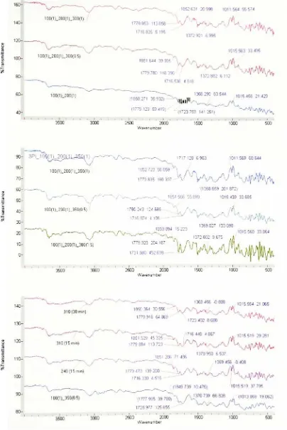
on each.2.4.1 Fourier Transform Infrared
Spectroscopy
(FTIR)
This technique has been usedto reveal theextent ordegree ofimidization
taking
place
in
the sample.Spectra
have been analyzedby
aband ratio method. Peakintensity
ratio
for
theimide
ring
stretch occurring at 1779 cm"1and areference aromatic peak at
1012 cm"1
(etheroxygen-to-aromatic
ring
stretching vibration) has beencalculated [16].Degree of
imidization
has been calculatedby
normalizing a sampleband ratio with oneshowingthemaximum bandratio. Foranalysis, each peak was enlargedto minimizethe
measurement errors [17]. A Bio-Rad Excalibur Series FTS 3000
instrument
was used toanalyzethe samples. ThepolymerandKBrpowder(IR
Grade)
weregroundedtoobtainagooddispersionandthespectra were recordedusingadiffusereflectancecell.
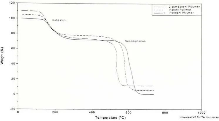
2.4.2 ThermogravimetricAnalysis
(TGA)
TGA indicates
(1)
if any weightlossoccurs dueto incompleteimidization,
or(2)
for
the Zr-pendent polymer, the extent ofdecomposition that takes place in the sampleduring
processing, if any. The decomposition of the Zr-pendent polyimide can becalculatedby:
Expected Wt ofundecomposedpolyimide
=
gZr02x
(\
moleZrO,\\ (\ moleZrpendentgroup")x(\ moleZrpendentmer^l xftTl
187.3g^ +9(
474.4gYl
ll23.2gZrO^
I
lmoleZr02)
Kl
moleZrpendentgrpJ
LUmoleZrJ
ll
molenon-JJ pendent mer pendentmer....Eqn. 2.1
Ifthe difference between the expected weight and the actual weight
is
0,
then0,
then either the sample has notbeen
completelyimidized
or someZ1O2
was lostfrom
the TGApan due to the airflow and ifthedifference between
the expected weightand the actual weight
is
<0,
it
means that the sample has decomposed at the chosenprocessingcondition.
A TA
Instruments
TGA2050
was usedtoperformtheanalysis. Samplesweighedbetween 10 and20 mgand were
heated
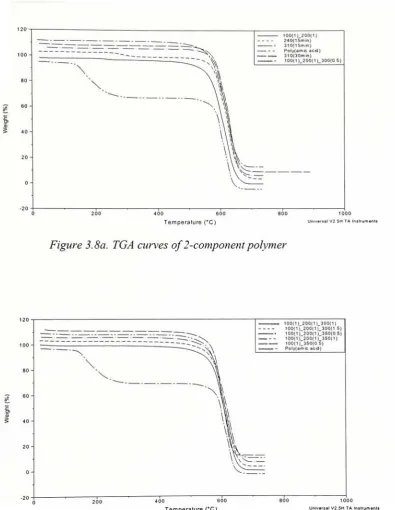
at10 C /min inair atmosphereupto 800 C.Molding
cycles usedfor fabrication
ofthe composite laminates in the autoclave have also been emulated in theTGA furnace to studydecomposition
taking
place in thepolymer,
if
any. The2-component,
parent and pendent poly(amic acid)s wereheated upto 370 Candheldatthis temperature
for
anhour innitrogen atmosphere.2.4.3 Differential
Scanning Calorimetry
(DSC)
This characterization technique
is
used toindicate
the effect of processing onglasstransition temperaturesofthedifferentpolymers.Itwouldalso
identify
thepresenceof unimidized polymer if any. The analysis was carried out in a nitrogen atmosphere (flow rate of80 mL/min) in a TA Instruments DSC 2010 machine. The samples were
hermetically
sealed and weighedbetween 5 and 10 mg. Thefollowing heating
cycle wasused:
Step
1:Ramp
@
10 C/minto450 CStep
2: Isothermal for 10minStep
3:Ramp
@
10 C/minto25 CStep
4: Isothermalfor 10 minStep
5:Ramp
@
10 C/minto450 CStep
6: Isothermal for 10minStep
7:Ramp
@
20 C/minto25 C2.5
Fabrication
of
Composite Laminates
A vacuum oven(National Appliance
Co.,
Model5831)
was used for making theprepregs and the laminates were fabricated in an autoclave
(Thermal Equipment
Corporation). The carbon and glass reinforced composites were
fabricated
attheCenter
2.5.1
Fabrication ofPrepregsPrepregs
aredefined
as areinforcing
materialimpregnated
with resin priorto themoldingprocess and cured
by
theapplication ofheat.
Theprepregs were fabricated usingthe conventional
hand
lay-up
technique. The amount ofresin needed for each ply wascalculated
by
following
theprocedure givenbelow:
Tomaintain a
fiber
toresin ratio of60:40by
weight,Wresin
needed=Wfiber
x40_
Eqn. 2.260
Fora 15 weight% solidssolution, theweight ofthesolution needed:
0.15=
Wresin
Eqn. 2.3"resin '
"solvent
Where,
Wresin
=Weight
oftheresin
(g),
Wsolvent
=Weight
ofthesolvent
(g),
andWresin+WsoiVent
=Weight
ofthesolution
(g
)
Theprocedure
for
makingtheprepregsisas follows:1)
In orderto make a4-ply
laminate,
asingle sheet of 11"x 7"
ofthe wovenfabric
wascut.
2)
The sheet wasweighedon alaboratory
electronicbalance and placedon a plastictray
coveredwith a releasefilm.3)
Theamountofresinandhence theamount of solutionneeded was thencalculatedto obtain the desired 60:40 fiber to resin
by
weight ratio using the equationsshownabove.
4)
Theweighed amountofsolutionwas pouredinabeaker,
plus some extra solutionwas weighedtocompensateforsolutionthatwouldstickonthewalls ofthe tray.
5)
The brushwasdipped inthesolution foraround 5minutestosaturateit.
6)
Theresin was appliedusingthebrushandtheexcess resin was squeezed outusingarollerthatalso facilitatedwetting thefabric.
7)
Resinwasthenapplied onthereverse side andtheexcess resin was squeezed out.9)
The prepregwas placedonthefilm andheated
at 65 C for 30minutes. Thiswasdone to retain some solvent
facilitating
the mobilityofthe polymer chains in thepresence oftheplasticizingaction ofthe solvent.
10)
The prepreg was weighed andif
the ratio offiber
to resin was not reached, thenmore resin was applied
followed
by heating
inthevacuum oven.1
1)
Theabove process was repeated until thedesired
ratiowasreached.12)
Thesheet wasthencutinto
fourplieseachhaving
adimensionof7"
x2.75".
13)
Theprepregs were wrappedin
an aluminum foiland storedinthecoldroom.For single-ply
laminas,
sheets of 7"x
4"
of the woven fabric were cut and
prepregs were madeusingthe above procedure. All theprepregsheets (single plyand
4-ply) had aresincontentof~52
%
by
weightto accountforthesolventlosses andthe lossof water
during
imidizationtaking
place in the autoclave. This was done based on thefollowing
calculation/ argument:Fora2-componentpolyimide,
molecular weight oftherepeat unit=510.44
g/mol
Sincetwomolecules of waterarelostupon
imidization,
loss
in
weightdueto water=36 x 100 =~ 7%510.44
Itwas also observedthat
during
the vacuum oventreatment oftheprepregs, there was alossof~4
weight% duetosolvent evaporation. In ordertoachieve40%
by
weightoftheresin,
resintobeappliedtothefibers= 40%+7%+4% = 51 %
2.5.2Fabrication ofLaminates
Forasingle-ply
lamina,
the prepregwas laidout ontheautoclavetable,
while formaking a
four-ply
laminate,
4 plies were stacked ontop
of each other. The entireassemblywasvacuumbaggedand placedinsidetheautoclave.
Composite
laminationwasperformed using a Thermal EquipmentCorporation autoclave under controlledpressure,
Table 2.3.
Autoclave Parameters
Recipe Parameters Units
Heating
CycleCooling
CycleTarget Temperature F 702 230
Soak Time min 60 1
Heating
Rate F/min 20 5Target Pressure psi 250 250
Target Vacuum
in.
Hg
30 302.5.3 Resin Content ofLaminates
Two methods were employed to calculate theresin content ofthe laminates after
autoclaveconsolidation.
Method I: Theresin content ofthelaminates was found accordingto ASTMD
2584-94,
Standard Test Method for Ignition Loss of Cured Reinforced Resins. A 1 cm x 1 cm
sample was cut from each laminate and the resin content was obtained
by following
theprocedure described below:
An empty ceramic crucible was heated in a furnace at 560 C for about 15
minutes. Itwas thencooledtoroomtemperature inadessicatorand weighed. The sample
wasplaced
in
thecrucibleandweighed precisely. Itwasburned in afurnace at560C forabout 1 hour. Theresin burnedoffcompletelyandthe cruciblewas allowedtocoolback
toroomtemperature
in
thedessicator. Theweight ofthe fiberswas recordedandtheresincontentwascalculated usingtheformulagivenbelow:
%
Resin Content=Wiaminate
- W
fibers Eqn. 2.4
W laminate
Where,
W
laminate=Weightofthecompositesample(g),
Wfibers=Weightofthefibers
(g),
andWlaminate- W
Method
II: This is a very rough technique employed todetermine
the resin content. Inthis method, the weight of a comparable size sheet of
fiber
was recorded before theapplication ofany resin. The
laminates
were then weighed on an electronicbalance afterfabrication,
and resin content wasdetermined
usingequation2.4.2.5.4
Machining
ofComposite Laminates
Various specialized techniques such as water-jet or laser cutting for machining
composite
laminates
have
been
developed
[13]. Prior to mechanicaltesting,
thecomposite
laminates
were machined using a laser beam and specimen edges weresmoothedusingsand paper(Grade
320)
toASTMrecommendeddimensions.2. 6 Mechanical Properties
of
Composite Laminates
Variousmechanical testssuch as
Tensile,
Flexural (three-pointbend),
Izod ImpactandDynamic Mechanical Analysis
(DMA)
were conducted onthecomposite specimens.Thetensile andDMA tests wereperformedon single ply laminaswhile the flexural and
Izod
impact
testswere performed onfour-ply
laminates.2.6.1 Tensile
Testing
Tensiletest
is
a measurement oftheabilityofthematerialtowithstandforces
thattend to pull
it
apart and to determine to what extent the material stretches beforebreaking. The tension test has been used to measure the tensile modulus, strength and
ultimate strain to failure for composites. Tests were performed on single ply laminas on
anMTS 45G Universal
Testing
Machine(U.T.M.)
accordingtoASTMD3039/D3039M-95a,
Tensile Properties ofPolymer Composite Materials. The machine was computercontrolledusingaTest Works
4
software.
2.6.1.1Specimen Preparation
Bonding
ofendtabsto tensilespecimenConventional dog-bone specimens fortensile
testing
have
atendency
to splitin
the region where the width changes. For fiber composites, uniform width
(rectangular)
used. Theend-tabs were
bonded
to the testspecimensto minimize stressconcentrationatload
introduction
regions at the specimen ends. A Hysol9303
grade adhesive (DexterAdhesives, Inc.)
was used tobond
the end-tabs to the tensile specimen. The proceduredescribed
belowwasfollowed [13]:
1)
Using
a sand paper(grade
220or 180),
theregions ofthepanelwheretheendtabsare
bonded
were sandedin
+45motions.
2) Using
a wirebrush,
theloose
particles werecarefullyremoved.3)
Thesurface was cleaned with acetone until alltheloosefibers
were removed.4)
The surface ofthe endtabs were sanded and cleaned according
![Figure 1.9. Typical vacuum bag assembly [11]](https://thumb-us.123doks.com/thumbv2/123dok_us/123330.11954/26.529.50.464.22.453/figure-typical-vacuum-bag-assembly.webp)