This is a repository copy of
PON Data Centre Design with AWGR and Server Based
Routing
.
White Rose Research Online URL for this paper:
http://eprints.whiterose.ac.uk/116818/
Version: Accepted Version
Proceedings Paper:
Alani, R, Hammadi, A, El-Gorashi, TEH et al. (1 more author) (2017) PON Data Centre
Design with AWGR and Server Based Routing. In: 19th International Conference on
Transparent Optical Networks (ICTON 2017). 19th International Conference on
Transparent Optical Networks (ICTON 2017), 02-06 Jul 2017, Girona, Spain. IEEE . ISBN
978-1-5386-0859-3
https://doi.org/10.1109/ICTON.2017.8024885
©2017 IEEE. This is an author produced version of a paper published in proceedings of
19th International Conference on Transparent Optical Networks (ICTON 2017). Personal
use of this material is permitted. Permission from IEEE must be obtained for all other uses,
in any current or future media, including reprinting/republishing this material for advertising
or promotional purposes, creating new collective works, for resale or redistribution to
servers or lists, or reuse of any copyrighted component of this work in other works.
Uploaded in accordance with the publisher's self-archiving policy.
[email protected] https://eprints.whiterose.ac.uk/ Reuse
Unless indicated otherwise, fulltext items are protected by copyright with all rights reserved. The copyright exception in section 29 of the Copyright, Designs and Patents Act 1988 allows the making of a single copy solely for the purpose of non-commercial research or private study within the limits of fair dealing. The publisher or other rights-holder may allow further reproduction and re-use of this version - refer to the White Rose Research Online record for this item. Where records identify the publisher as the copyright holder, users can verify any specific terms of use on the publisher’s website.
Takedown
If you consider content in White Rose Research Online to be in breach of UK law, please notify us by
1
PON Data Centre Design with AWGR and Server Based Routing
Randa Alani, Ali Hammadi, Taisir E.H. El-Gorashi, and Jaafar M.H. Elmirghani
School of Electronic and Electrical Engineering, University of Leeds, LS2 9JT, United Kingdom
ABSTRACT
Passive Optical Networks (PONs) with their proven performance in access networks can provide solutions to the challenges facing modern data centres. In this paper, we study a PON architecture where Arrayed Waveguide Grating Routers (AWGRs) and servers are used to route traffic. We optimize the wavelength routing and assignment in the design and show through a benchmark study that the PON data centre architecture reduces the power consumption by 83% compared to the Fat-Tree architecture and 93% compared to the BCube architecture.
Keywords: passive optical network (PON), data centre, energy efficiency, arrayed waveguide grating routers
(AWGRs).
1. INTRODUCTION
The continuous growth in Internet-connected devices results in significant increase in data centres’ traffic which in turn necessitates the development of scalable, high bandwidth, low power consumption data centre architectures. Optical data centre architectures, precisely Passive Optical Networks (PONs), with their proven performance in access networks can provide efficient solutions to support connectivity inside modern data centres [1]. In this regard, we proposed different novel PON architectures to manage the inter-rack and intra-rack communication of a data centre as in [2-6]. In this paper, we further study one of the PON designs proposed in [6] where routing is performed by Arrayed Waveguide Grating Routers (AWGRs) and servers. We investigate the wavelength routing and assignment within the proposed architecture. Moreover, the power consumption of this design is compared to the traditional data centre architectures.
The reminder of this paper is structured as follows: In Section 2, the proposed PON architecture is described along with its wavelength routing and assignment. In Section 3, a benchmark study is presented to compare the power consumption of our proposed design against Fat-Tree and BCube traditional data centre architectures. Finally, conclusions are provided in Section 4.
2. THE PROPOSED PON DATA CENTRE ARCHITECTURE
The proposed PON architecture [6] achieves energy-efficiency and high speed interconnection by eliminating the use of electronic switches that consume considerable amount of energy. It uses AWGRs to maintain communication instead. In addition to the AWGRs, the architecture employs special servers which minimize the tuneable laser units needed comparedto the PON architecture based on AWGRs discussed in [2].
In this design, as shown in Fig. 1, the servers in PON cell are placed into groups. A group is made of multiple subgroups where the number of servers hosted by a subgroup depends on the splitting ratio of the TDM PON connected to it. For example a group can host 16 servers placed into two subgroups each of 8 servers.
This architecture involves two types of communication: intra group, and inter group communication. Intra group communication can be either between servers in a subgroup (intra subgroup communications) or between servers in different subgroups in the group (inter subgroup communication). The subgroups in each group are connected to a special server whose task is to maintain the inter subgroup, and inter group communication.
Intra subgroup communication is achieved using a Fiber Bragg Gating FBG which reflects only the wavelength assigned for intra subgroup communication. All subgroups can use the same wavelength for intra subgroup communication due to the fact that this wavelength does not pass through the FBG to other groups. Accordingly,
the design of the servers’ transceivers will be simplified and unified. Also, as the reflected wavelength has one way of communication, it is possible to use the same wavelength for transmitting and receiving. Based on the above, servers should get permission from the special server (that lays after the FBG) for intra subgroup communication wavelength. This will help to eliminate collision and controls channel access contention.
2
Figure 1. Proposed PON cell architecture.
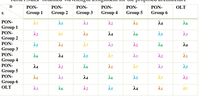
A Mixed Integer Linear Programming (MILP) model is developed, where the routing and wavelength assignment within the AWGRs of the PON cell are optimized to support inter group interconnections. This model guarantees that the connection between two groups is established by using only one wavelength. This model is used to optimize the wavelength routing and assignment for the proposed PON cell architecture shown in Fig. 1 which consists of 92 servers placed into 6 groups. Table 1 shows the resulting wavelength assignment for inter groups communication and communication with the OLT.
Table1.MILP obtained Wavelength assignment for the proposed architecture
D S
PON-Group 1
PON-Group 2
PON-Group 3
PON-Group 4
PON-Group 5
PON-Group 6
OLT
PON-Group 1 7 5 3 2 1 4 6
PON-Group 2 2 7 1 4 6 5 3
PON-Group 3 5 1 7 3 2 6 4
PON-Group 4 6 4 5 7 3 2 1
PON-Group 5 4 2 6 1 7 3 5
PON-Group 6 1 3 4 6 5 7 2
OLT 3 6 2 5 4 1 7
3. POWER CONSUMPTION BENCHMARK
3
The Fat-Tree architecture [7] is characterized by the employment of unified commodity switches in all layers: core, aggregation, and access. As shown in Fig. 2, this architecture is composed of a number of pods that matches
the number of commodity switch’s ports k. Each pod hosts k servers that are connected by access switches which
in return are connected by aggregation switches that communicate with each other through core switches.
As a General rule, Fat-Tree data centre architecture can host servers in all pods.
Figure 2. Fat-Tree Architecture of k= 4.
[image:4.595.119.480.156.274.2]On the other hand, the BCube architecture [8] is characterized by the use of servers for routing and forwarding decisions along with the switches. As shown in Fig. 3, this recursive architecture’s elementary unit is called BCube0. Accordingly, BCube0 hosts a number of servers, n, that matches the number of ports of the single commodity switch connecting them. Furthermore, combining n BCube0s by connecting them via an n commodity switches forms BCube1. In general, BCube data centre architecture is referred to as BCubek which is composed of n BCubek-1s, switches, and k+ 1-port servers.
Figure 3. BCube Architecture of n= 4, k= 1.
For the benchmarking, a Fat-Tree architecture of 24 pods hosting 3456 servers, and 48 pods hosting 27648 servers are considered. Cisco 2960-24TC-L switches are employed to connect servers in the 24 Pod scenario while Cisco 2960-48TC-L switches are used to connect servers in the 48 pod scenario.
BCube architectures with n=8 are also considered with k=2 hosting 512 servers, k=3 hosting 4096 servers, and k=4 hosting 32768 servers. The switches used to connect servers in BCube architecture are Cisco 2960-8TC-L switches. Finally, our proposed architecture’s power consumption is evaluated using 6 groups hosting 92 servers. The power consumption of the devices of the different architectures used in this benchmark study are shown in Table 2.
Table 2. Device’s power consumption
Device Power Consumption 10Gb/s tuneable ONU 2.5W [9]
Server’s transceiver 3W [10] Cisco 2960-8TC-L 12W [11] Cisco 2960-24TC-L 27W [12] Cisco 2960-48TC-L 39W [13] 10Gb/s OLT port 125W [14]
[image:4.595.121.478.368.491.2]4
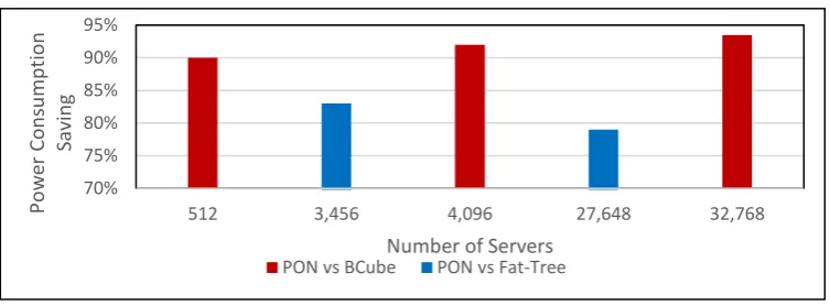
Figure 4. Benchmark study results.
It can be noticed that the BCube topology is the highest power consumer in this study. This is due to the fact that the BCube architecture depends on servers for routing in addition to the commodity switches. This results in servers having multiple transceivers in order to handle connectivity with all the levels. Therefore, as the number of levels increases in the BCube topology, the power consumption increases as more transceivers are needed to establish connections to switches in every level. Accordingly, the power saving of our proposed design compared to BCube increases with the increase in the number of BCube’s levels. On the other hand, the savings of our design compared to the Fat Tree architecture decreases with increase in the number of servers. This is due to the fact that the power consumption of Fat-Tree topology increases non-linearly when the number of pods increases.
4. CONCLUSIONS
This paper has studied a PON data centre architecture where Arrayed Waveguide Grating Routers (AWGRs) and servers are used to route traffic. The architecture is a scalable design that can be expanded to support hundreds of thousands servers. We have optimized wavelength routing and assignment for the inter group communication using a MILP model and presented a range of results. The PON data centre design is energy efficient as it discards the power hungry switches and replaces them by passive optical devices. A benchmark study shows that our proposed architecture reduces the power consumption by 83% compared to the Fat-Tree architecture and by 93% compared to the BCube architecture.
ACKNOWLEDGEMENTS
The authors would like to acknowledge funding from the Engineering and Physical Sciences Research Council (EPSRC), INTERNET (EP/H040536/1) and STAR (EP/K016873/1). Mrs. Randa A. Alani would like to acknowledge The Iraqi Ministry of Higher Education and Scientific Research for funding her scholarship. All data are provided in full in the results section of this paper.
REFERENCES
[1] McGarry, M.P., M. Reisslein, and M. Maier, WDM Ethernet passive optical networks. IEEE Communications Magazine, 2006. 44(2): p. 15-22.
[2] Hammadi, A., T.E. El-Gorashi, and J.M. Elmirghani. High performance AWGR PONs in data centre networks. in Transparent Optical Networks (ICTON), 2015 17th International Conference on. 2015. IEEE.
[3] Hammadi, A., et al. Server-centric PON data center architecture. in Transparent Optical Networks (ICTON), 2016 18th International Conference on. 2016. IEEE.
[4] Hammadi, A., T.E. El-Gorashi, and J.M. Elmirghani. Energy-efficient software-defined AWGR-based PON data center network. in Transparent Optical Networks (ICTON), 2016 18th International Conference on. 2016. IEEE.
[5] Hammadi, A., et al. Resource provisioning for cloud PON AWGR-based data center architecture. in Networks and Optical Communications (NOC), 2016 21st European Conference on. 2016. IEEE. [6] Elmirghani, J., T. EL-GORASHI, and A. HAMMADI, Passive optical-based data center networks, 2016,
Google Patents.
[7] Al-Fares, M., A. Loukissas, and A. Vahdat. A scalable, commodity data center network architecture. in ACM SIGCOMM Computer Communication Review. 2008. ACM.
[8] Guo, C., et al., BCube: a high performance, server-centric network architecture for modular data centers. ACM SIGCOMM Computer Communication Review, 2009. 39(4): p. 63-74.
[9] Grobe, K., et al., Cost and energy consumption analysis of advanced WDM-PONs. IEEE Communications Magazine, 2011. 49(2).
70% 75% 80% 85% 90% 95%
512 3,456 4,096 27,648 32,768
P o w e r C o n su m p ti o n S av in g
Number of Servers
5
[10] Gyarmati, L. and T.A. Trinh. How can architecture help to reduce energy consumption in data center networking? in Proceedings of the 1st International Conference on Energy-Efficient Computing and Networking. 2010. ACM.
[11] Cisco. Data sheet of Cisco-2960-8TC-L DataSheet. Available from:
http://www.cisco.com/c/en/us/support/switches/catalyst-2960-8tc-l-compact-switch/model.html. [12] Cisco. Data sheet of Cisco-2960-24TC-L DataSheet. Available from: :
http://www.cisco.com/c/en/us/support/switches/catalyst-2960-24tc-l-switch/model.html.
[13] Cisco. Data sheet of Cisco-2960-48TC-L DataSheet. Available from:
http://www.cisco.com/c/en/us/support/switches/catalyst-2960g-48tc-l-switch/model.html#DataSheets. [14] Baliga, J., et al. Energy consumption in access networks. in Optical Fiber communication/National Fiber