Int. J. Electrochem. Sci., 6 (2011) 2609 - 2631
International Journal of
ELECTROCHEMICAL
SCIENCE
www.electrochemsci.orgElectrochemical Preparation of Particles for
X-Ray Free Electron Laser Based Diffractive Imaging
Benedetto Bozzini1,*, Marco Guerrieri1, Flavio Capotondi2, Ivonne Sgura3, Elisabetta Tondo1. 1Dipartimento di Ingegneria dell’Innovazione, Università del Salento, via Monteroni, 73100 Lecce – Italy
2
Sincrotrone Trieste S.C.p.A., ELETTRA, S.S. 14 km 163.5, Area Science Park, 34149 Trieste, Italy 3
Dipartimento di Matematica, Università del Salento, via Arnesano, 73100 Lecce – Italy *
E-mail: [email protected]
Received: 21 May 2011 / Accepted: 5 June 2011 / Published: 1 July 2011
The FERMI X-ray Free Electron Laser (XFEL) at Elettra will be a powerful tool of investigation in new fields of materials science, based on ultrashort EUV pulses. Among cutting-edge applications, diffractive imaging of nano- and microparticles is a specially hot topic. In this field, the particle-injection approach is regarded as optimal in terms of imaging quality. The possibility of pre-treating the particles with electrochemical approaches at the insertion station is expected to offer additional flexibility for users. Electrochemical modification of the particles can be straightforwardly obtained by the bipolar approach and extraction of a particle stream into the injector will safely occur in times allowing the possibility of studying intact electrochemical double layers according to the electrode-emersion method. In this paper, a first section is dedicated to: (i) the definition of a mathematical model describing the bipolar electrochemical behavior of particles; (ii) its implementation in a finite element analysis package; (iii) the discussion of results of numerical simulations, allowing to predict the effects of relevant process parameters. In a second section, the experimental part is described, consisting in: (i) the fabrication of a packed-bed and a fluidised-bed electrochemical reactor, able to support the bipolar electrochemical operation of micrometric particles; (ii) the treatment in aqueous environment of Cu and WC particles; (iii) the characterisation by SEM and XRD of the treated powders, in order to pinpoint surface changes induced by the electrochemical process.
Keywords: X-ray Free Electron Laser, particle injection, bipolar electrochemistry, fluidized bed electrode, coherent diffractive imaging.
1. INTRODUCTION
research, and one of the most important themes refers to the ability to reveal the structure and dynamics evolving at the nanoscale, through coherent X-ray scattering or diffractive imaging. However, an important requirement is to set the tolerable pulse fluence in order not to prevent the radiation damage, which requires detailed knowledge of the mechanisms of interaction of these ultrafast and intense photon probes with the matter under investigation. Radiation damage is the object of intense studies [1-9] and the dynamics of electrons and ions following the ionisation processes in non-linear regime of FEL irradiation and the Coulomb explosion have already been discussed in current theoretical models [10].
In the frame of the collaboration with scientists at Elettra Synchrotron laboratory involved in the construction of instrumentation and programming future experiments using the FERMI free electron laser that will start operation in 2011, the Electrochemistry Group of University of Salento is developing a research program aiming at understanding and controlling the radiation damage undergone by nanoparticles or clusters in electrochemical environment. The energy range of FERMI is in the EUV soft X-Ray regime (the lines FEL-1 and FEL-2 will operate at 100-20 and 20-4 nm wavelengths, respectively) in the first harmonic and it is expected to reach 1 nm wavelength in the third harmonic. Typical prospective experiments are based on coherent diffractive imaging (CDI), which uses iterative phase-reconstruction algorithms to invert the scattering patterns and thereby reconstruct images of objects with resolution limitations imposed by the X-ray wavelength. They will consist in pump-probe measurements of electrochemically treated particles that will allow the data acquisition of observables such as the critical time corresponding to the onset of particle expansion and its explosion rate. The electrochemical effects on these events can be taken into account in terms of the formation of a coating, modified layer or even interfacial double layer, obtained by a bipolar electrochemistry process, along the lines detailed below.
Experiments with femtosecond X-FELs have been reported with three types of sample: (i) bulk [2, 6] and multilayered [5] solids, (ii) film-supported particles - typically on Si3N4 membranes - [11] and (iii) particles or clusters injected into the analysis chamber [9, 12, 13]. The last option is the one of choice, because the absence of scattering from the supporting membrane results in an enhancement of the signal-to-noise ratio. Pump-probe measurements have been performed with configurations of types (ii) and (iii).
particle and gives rise to the formation of a positively-charged outer layer [15, 16]. The charged outer zone suffers Coulomb-explosion and - on a longer timescale - the neutral core of the particle expands hydrodynamically. In this framework, the chief observables are: (i) the critical delay corresponding to the onset of particle growth, (ii) the expansion rate of the particle. From this particular point of view, the scope of the present work is thus to propose an experimental approach able to pinpoint the potential role of electrochemistry in the design of particle expansion experiments.
The dynamics of electrons and ions as well as the ionisation processes ensuing FEL irradiation of clusters - aimed at describing the processes leading to Coulomb explosion - have been attacked from the theoretical point of view according to two chief approaches: Monte Carlo computations [12, 17, 18] and solution of Boltzmann equations [10, 15, 16, 19, 20]. In the latter approach, a statistical treatment is adopted studying the charge dynamics in terms of electron and ion densities in phase space, based on semiclassical Boltzmann equations. Such densities are continuous functions and therefore the method applies also to large systems and the numerical difficulties of the method depend on the geometry of the integration domain in phase space rather than on the dimensions of the cluster or nanoparticle being studied. In fact, the Boltzmann approach for single-particle densities is a rather strong approximation within the realm of statistical physics, implying that two-body collision effects dominate, a situation typical of short-range interactions: this is not really the case with critical Coulomb interactions, but going beyond this approximation would mean attacking the problem with Liouville equations for many-particle joint density functions. For the present purpose, we chose to base the introduction of electrochemical effects following the ionisation physics underlying the model [10].
Electrochemistry offers a wide range of opportunities for surface material modifications of samples both in film and particle forms. Such kinds of modifications can in general be described as the formation of a controlled surface layer of thicknesses ranging from monoatomic or monomolecular to thick films. The relevance of this kind of systems is critical for X-FEL experiments based on coulomb explosion. For the present purpose, we can consider two limiting cases, in terms of extent of particle modification: (i) formation of just an interfacial electrical double layer and (ii) deposition of a surface film.
As far as the former case is concerned, it is worth noting that, notwithstanding the fact that the structure of the electrochemical double layer is an insightfully investigated topic (e.g. [21]), still a lot has to be learnt about this system, especially in ionic liquids and molten salts [22]. Regardless of the details of the structure and molecular arrangement at the electrified interface, in any case a potential difference develops across a potentially subnanometer thick interface (typically, but not exclusively, between a solid electrode and an electrolyte), corresponding to localised electric fields of the order of 109 V m-1. Such double layers can be formed at nanoparticles [23] and can be preserved after emersion of the film or nanoparticle from the electrolyte [24]. In this way, electrochemistry can be carried out in a preparation chamber and electrochemically modified particles can be injected into the analysis chamber to reach the interaction volume with state-of-the-art methods (see, e.g. [13]) with an intact double-layer structure. An adequate choice of the sign and range of values of the interfacial potential can thus be regarded as giving rise to a tunable potential barrier for tunneling of electrons of suitable energies from the particle into the surrounding emersed electrolyte layer [25] or into the plasma formed by transient ionisation of the outer shell of the particle, after irradiation. In fact, it has proved that plasmas can be treated as electrolytes and combinations of metals and plasmas can be dealt with as electrochemical cells, giving rise to the typical electrochemical phenomenology, as far as thermodynamics [26], kinetics [27] and materials science [28] are concerned. Within the framework of the Boltzmann approach of [10], such potential barrier contributes additively to the electromagnetic force acting as a coefficient for the term e q, where: e
r,q,t is the electron density, r is the position and q is the momentum of the particles. A more straightforward impact of electrochemistry in particle explosion dynamics is obtained by simply forming an external layer of modified material, either in terms of deposition of extraneous material or of oxidation or reduction of the base material (see examples in the present work): this kind of approach can be handled within the conceptual framework of tamper layer effects on Coulomb explosion [29].Bipolar electrochemistry consists in immersing electrically conducting particles in a poorly conductive electrolyte contained in an electrolytic cell; the application of an electric field across the feeder electrodes induces cathode-anode pairs on each isolated particle, thus working as a bipolar electrode. With respect to the monopolar approach, bipolar electrochemistry offers the advantage to induce polarisation of the particles without direct physical connection with a power source.
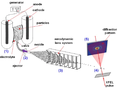
application of a voltage across the feeder electrodes will induce an electrochemical polarisation of the particles placed inside the solid electrolyte, in accordance with the concept of bipolar electrochemistry. In the second approach the particles will be electrochemically pretreated in a cell and, after emersion from the electrolyte, will be delivered in the interaction region through an aerodynamic lens system, able to produce narrow particle streams [30, 31] (Figure 1).
Figure 1. Schematic representation of the experiment. The bipolar electrochemical reactor produces a surface modification of the particles (1); a particles stream, extracted from the reactor, is injected (2) in the aerodynamic lens system (3), able to produce a narrow particle stream. Single particles interact with the FEL pulse (4); diffracted X-rays reach the detector (5).
[image:5.596.60.523.180.529.2]
order to pinpoint surface changes induced by the electrochemical process. According to literature [34, 35], dissolution of the metal in Cu2+ ions and electrodeposition of novel Cu nanostructures are expected to take place on the surface of Cu particles. Moreover in presence of oxygen, it is possible to form oxides (mainly Cu2O) as a result of either Cu oxidation or reduction of Cu2+. Instead, the prediction of the electrochemical behavior of WC is extremely difficult, owing to its complex bulk and surface properties. When WC is exposed to water, it undergoes continuous oxidation and dissolution; the amount of oxides influences strongly the WC electrocatalytic properties [36, 37].
2. MATHEMATICAL MODEL OF BIPOLAR ELECTROCHEMICAL BEHAVIOR OF PARTICLES
A simple model describing the bipolar behavior of particles in an electrolytic cell is implemented with COMSOL Multiphysics.
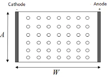
Figure 2. Schematic view of bipolar behavior of a 2D array of particles.
A representative scheme of the experimental system of interest is depicted in a two-dimensional region in Figure 2: the application of an electric field between two feeder electrodes induces cathode-anode pairs on electrically conductive particles placed in an array and isolated immersed in a poorly ionically conductive electrolyte. In particular, we consider material constants corresponding to Cu powder in ultrapure water, having a very low electrical conductivity (σe = 5 10-6
[image:6.596.126.486.335.591.2]
2.1. Model equation
The potentials in the metal particles and in the electrolyte are indicated as Φ1 and Φ2 respectively. The charge balance equation must be satisfied in each phase by defining Laplace’s equation as follows:
2 1=0
2 2=0 2.2. Domain of integration
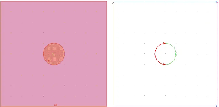
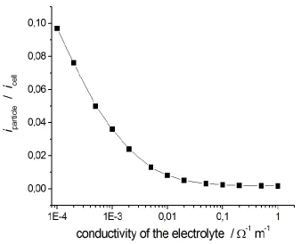
We have seen in Figure 2 a 2D schematic diagram of the bipolar electrochemical process. On the basis of symmetry considerations detailed in [38], the domain of integration can be reduced to a square of side l=1 m representing the electrolytic medium, with at its center one disc of diameter of 200 nm (Figure 3-a).
Figure 3. (a) Domain of integration for the model (b) Definition of the domain boundary.
2.3. Boundary conditions
Since we chose to model the process as a steady one, initial conditions are not required. Instead, we refer to Figure 3-b and discuss the equations to be set on the edge of the domain. The lateral borders represent the two feeder electrodes for which the potential Φ2 is fixed:
Φa = 1 V (anode, magenta line); Φc = -1 V (cathode, black line);
The top and bottom edges, drawn in blue, correspond to insulating conditions that can be written as:
[image:7.596.121.478.330.505.2]
The particle-electrolyte interface is the location where the bipolar electrochemical process occurs; here both the anodic and cathodic reactions take place. We can consider approximately that the half of metal disc close to the cathode is polarised anodically, thus the Cu dissolution occurs:
Cu 2e
Cumetal 2
while on the other half, polarised cathodically, we have the reduction of hydrogen ions:
2e H 2OH O
2H2 2
The kinetics of these reactions is described by Butler-Volmer equations, respectively as:
H cat H 0 2 1 H an H 0 2 1 H 0 cat Cu cat Cu 0 2 1 Cu an Cu 0 2 1 Cu 0 an exp exp exp exp B B i i B B i i
where i0 is the exchange current density, Ban is the anodic Tafel slope, Bcat is the cathodic Tafel slope and Φ0 is the equilibrium potential; their values, derived from the literature (e.g. [39]), are:
i0Cu=24 A m-2, BanCu=BcatCu=0.052 V, 0Cu=0.137 VSHE, i0H=8.1×10⁻³ A m-2, BanH=BcatH=0.046 VSHE, 0H=-0.414 VSHE.
The boundary conditions for the particle-electrolyte interface can be written as: (anodic current density, red line): e×n2=ian
(cathodic current density, green line): e×n2=icat
Here for simplicity we have considered only two types of electrochemical reactions, occurring on the surface of the Cu particles (Cu dissolution and H2 evolution). Nevertheless, when the Cu ions, produced by the anodic reaction, reach the opposite particle, electrodeposition of Cu starts simultaneously with the H2 bubble evolution. Of course, any electrochemical reaction or combination of electrochemical reactions - for which kinetic constants are available - can be easily incorporated in the model.
2.4. Results of the numerical simulations
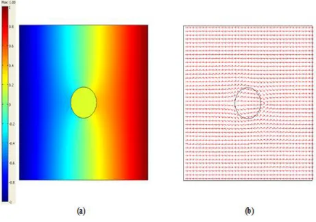
to the vectorial current circulating in the cell. An ionic current flows between the cathode and the anode; on the surface of the metal disc the occurrence of both anodic and cathodic reactions allows the passage of a faradaic current.
Figure 4. (a) Spatial potential distribution (b) Potential flux distribution (arrows) - proportional to the current density vector distribution.
Current distribution and intensity into the particles depend on several parameters, among which the chief ones are: the applied electric field intensity, the ratio between the volumes of particles and electrolyte, the electric properties (i.e. conductivity) of metal and electrolytic solution and the kinetics of the electrochemical reactions occurring at the metal-electrolyte interfaces.
2.5. Effect of the kinetic constants
[image:9.596.71.532.155.479.2]
Figure 5. (a) Effect on current distribution changing the kinetic constants (b) Normalized current distribution on the particle surface for three different sets of kinetic parameters, whose numerical values can be found in Section 2.4.
2.6. Effect of the particles density in the electrolyte
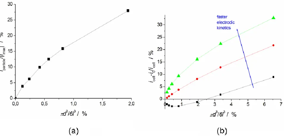
Figure 6. (a) Fraction of current flowing in the metal particles as a function of powder density in the electrolyte (b) Total current change as a function of the powder density, established by varying the size of the domain geometry.
[image:10.596.77.523.72.299.2] [image:10.596.64.541.422.651.2]
square integration domain is the numerical way we adopt to simulate a higher density of particles in the electrolyte, defined as the ratio of their volumes:
3
6
l d
. From numerical simulations, we deduce that the fraction of faradic current flowing in the particles (iparticle) increases with the particle density (Figure 6-a). In fact, when a considerable amount of particles is suspended in the solution, flow of an electronic current in the particles, resulting from the charge transfer at the electrolyte-metal interface, is more energetically convenient than the passage of an ionic current through the electrolyte around the particles. Figure 6-b reports the relative change of the cell current (icell) with respect to its value calculated in the absence of particles (i0) as a function of the powder density. We observe that below a critical density value, the bipolar operation of metal particles dispersed in the electrolyte induces total current reduction (black line). This occurs when the bipolar process onto particles has a higher energetic cost than the ohmic drop in the space of electrolyte occupied by particles, but smaller than that around them. In fact, by setting faster electrodic kinetics, and thus by lowering the energy needed for the occurrence of the anodic and cathodic reactions on the particles, we find an upward trend of the cell current for any value of density (red and green lines).
2.7. Effect of the electrical conductivity of the electrolyte
[image:11.596.130.468.460.734.2]In order to quantify the effect of the ratio of the ionic and metallic conductivities, we solved our model by setting different values of the electrolyte electric conductivity, keeping constant that of the metal.
We observe that, of course, the total cell current increases with decreasing resistivity of the electrolyte because the drop in the ionic medium decreases. Moreover, one can observe from Figure 7 that less current passes through the metal particles in correspondence of higher values of electrolyte conductivity. In fact, the passage of an ionic current within the electrolyte is more energetically convenient than charge transfer at metal-electrolyte interface.
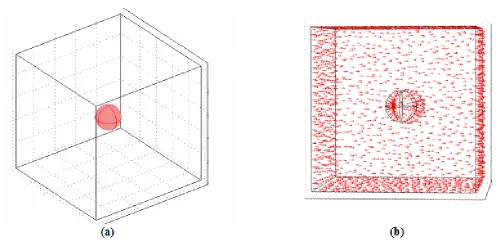
2.8. Three -dimensional model
So far we have considered a mathematical model for the description of the experiments of our interest under the assumption of plane geometry; now we present the model with a three-dimensional geometry of the electrochemical cell.
Figure 8. (a) The 3D domain of integration (b) Potential flux distribution - (arrows), proportional to the current density vector distribution.
[image:12.596.47.548.284.535.2]
confirm respectively the trends of Figures 6 and 7. We can thus conclude that 2D and 3D simulations yield essentially the same results, with the considered geometry.
3. EXPERIMENTAL RESULTS
In order to prove the bipolar behavior of micrometric metal powder in an electrolytic cell and to validate our numerical model, we carried out experimental investigations in packed-bed and in fluidised-bed electrochemical reactors.
3.1. Packed-bed electrochemical reactor
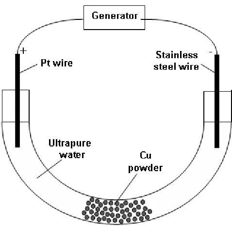
The packed-bed reactor is schematically depicted in Figure 9.
Figure 9. Scheme of the packed-bed reactor.
[image:13.596.176.415.319.552.2][image:14.596.146.450.132.361.2]
of nanoparticles appearing as white spots. A more insightful characterization of these compounds is provided below in Section 3.2.
Figure 10. SEM image at magnification 2,000× of Cu powder after electrochemical treatment.
[image:14.596.80.513.417.724.2]
Moreover, from Figure 11, we can pinpoint the appearance of peculiar, anemone-like structures, consisting of hollow tube-like metal deposits. In the literature, cognate deposit shapes are reported at gas-evolving electrodes, with similar morphologies though more extended and exhibiting shallower holes [40], called honeycomb-like structures. Cu particles do not behave as inert electrodes, so electrochemical reactions occurring on them are not restricted to water electrolysis (hydrogen and oxygen evolution), but also include Cu dissolution and redeposition. When both reactions of reduction of hydrogen ions and of Cu ions take place on the same electrodic location, hydrogen bubbles can act as templates around which the metal grows, resulting in the observed anemone structures. The formation of anemones was favored by the trapping of H2 bubbles in the packed-bed of Cu particles establishing in the lower section of the cell. Of course, in a packed-bed direct electrical contact is present among particles and pure bipolar behavior cannot be ensured. In order to overcome such limitation, we performed other experiments with a fluidised-bed electrochemical reactor, able to keep the particles electrically insulated in the electrolyte.
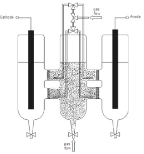
3.2. Fluidised-bed electrochemical reactor
We used the fluidised-bed reactor depicted in Figure 12, allowing complete separation of the fluidised-bed from both feeder electrodes and higher cross-section of the ionic contact between the powder and electrode compartments.
[image:15.596.150.437.420.727.2][image:16.596.122.431.238.490.2]
This consisted of three glass compartments communicating through four glass frits which acted as ionic contact and hindered the passage of the particles. The external cylinders were used to contain two graphite bars connected to the voltage generator, while the central one contained the powder fluidised in ultrapure water by a gas flow. Alternatively, four stripes of graphite paper, which could be immersed in the electrolyte up to the glass frits separating the central compartment from lateral ones, could be used in order to reduce the ohmic drop in the ionic branch of the circuit. In order to prevent the accumulation of powder in areas adjacent to the membranes, we set up a fluidisation system that blew gas not only from the bottom but also in the zones close to membranes.
Figure 13. Cell resistance as a function of fluidising air flow for the fluidised-bed reactor. The error bars correspond to 1 standard deviation. The red line is just a guide for the eye.
we report the mean value of the cell resistance with relative standard deviation, recorded at the different flow conditions.
We also performed experiments aimed at testing the effects of particle density in the electrolyte predicted by our computational model.
Figure 14. Comparison of measured (black squares) and computed (red line, corresponding to the following kinetic constants: i0cat=i0an=2400 A m-2, Bcat=0.046 V, Ban=0.052V relatives changes in cell current as a function of the density of particles added to the electrolyte, expressed as mass of particles (Mparticles) divided by mass of electrolyte (Melectrolyte).
A voltage of 350 V was fixed between the two feeder electrodes. We started the test with just ultrapure water and added 5 g of Cu powder for five times. The total current flowing through the cell was recorded during the experiment. In order to highlight the current increase, due to the addition of Cu particles behaving in a bipolar manner, we removed the background of increasing current attributable to other factors, such as temperature or pH variations and extracted quantities representing the purely bipolar effect: we found that these secondary effects could be accounted for by removing a decaying exponential from the raw current data, leaving clear current jumps, correlated with particle additions: pure particle effects, gauged as
cell 0 cell
i i i
[image:17.596.106.457.168.468.2]
comparison (red line in Figure 14). The experimental data thus confirm the trend predicted by numerical computations.
Material-preparation experiments were run potentiostatically with a cell voltage of 350 V for 24 h, employing Cu and WC powders and air or nitrogen as fluidisation gases. The treated powders were characterised through X-Ray Diffraction (XRD) analysis and SEM imaging.
Figure 15. X-ray diffractograms of Cu powder as received (black plot) and after electrochemical treatment with air (red plot) and N2 (green plot) fluidisation.
Figure 15 shows XR diffractograms of Cu powder as received and treated in the fluidised bed reactor operated with air and N2. In the diffractogram of the un-treated powder, five well defined peaks of the Cu phase are observable, in correspondence of characteristic angles in according to reference data. XRD of both air- and N2-fluidised powders reveal that three extra peaks are present, attributable to the Cu2O phase. The formation of the Cu2O phase is less efficient with N2 fluidisation, since oxidation is merely electrochemical in this case. From SEM micrographs of Figure 16, we observe that both air- and N2-fluidised particles show on their surface the formation of a distribution of nanometric particles, like those obtained with the packed-bed reactor.
[image:18.596.106.463.182.486.2]
been reported here for brevity. X-ray diffractograms of the treated WC sample (Figure 17) show, apart from the well defined peaks of the crystalline phase WC, wide bands, attributable to amorphous oxides formed during the bipolar electrochemical operating of the particles.
[image:19.596.126.474.147.702.2]
Figure 17. X-ray diffractograms of WC powder as received (blue plot) and after electrochemical treatment with N2 fluidisation (green plot).
4. CONCLUSIONS
[image:20.596.110.458.72.372.2]
the passage of an ionic current is energetically more convenient than to charge transfer at metal-electrolyte interface.
We have validated our numerical results by experiments of bipolar electrochemistry performed in packed-bed and fluidised-bed reactors with micrometric Cu and WC powders. SEM images of the surface of treated Cu powder show: (i) the formation of peculiar structures, consisting of hollow tube-like metal deposits (anemones) and favored by the Cu powder; (ii) the formation of Cu2O nanoparticles decorating Cu particles and (iii) amorphous WOx coating WC particles.
ACKNOWLEDGMENTS
The authors wish to express their deepest gratitude to Dr. Maya Kiskinova, head of Head of Microscopy Projects of Sincrotrone Trieste S.C.p.A., ELETTRA, Italy, in charge of the Imaging activities of the FERMI@ELETTRA XFEL for useful discussions that have been crucial in addressing the key aspects of this research as well as for critical reading of the manuscript.
References
1. M.F. DeCamp, D.A. Reis, D.M. Fritz, P.H. Bucksbaum, E.M. Dufresne and R. Clarke, J Synchrotron Radiat 12 (2005) 177
2. N. Stojanovic, D. Von der Linde, K. Sokolowski-Tinten, U. Zastrau, F. Perner, E. Förster, R. Sobierajski, R. Nietubyc, M. Jurek, D. Klinger, J. Pelka, J. Krzywinski, L. Juha, J. Cihelka, A. Velyhan, S. Koptyaev, V. Hajkova, J. Chalupsky, J. Kuba, Th. Tschentscher, S. Toleikis, S. Düsterer and H. Redlin, Appl. Phys. Lett. 89 (2006) 241909
3. K. J. Gaffney and H.N. Chapman Science 316 (2007) 1444
4. S.P. Hau-Riege, R.A. London, H.N. Chapman and M. Bergh, Phys. Rev. E, 76 (2007) 046403 5. S.P. Hau-Riege, H.N. Chapm, J. Krzywinski, R. Sobierajski, S. Bajt, R.A. London, M. Bergh, C.
Caleman, R. Nietubyc, L. Juha, J. Kuba, E. Spiller, S. Baker, R. Bionta, K.S. Tinten, N. Stojanovic, B. Kjornrattanawanich, E. Gullikson, E. Plönjes, S. Toleikis and T. Tschentscher, Phys. Rev. Lett. 98 (2007) 145502
6. A.M. Lindenberg, S. Engemann, K.J. Gaffney, K. Sokolowski-Tinten, J. Larsson, P-B. Hillyard, D.A. Reis, D.M. Fritz, J. Arthur, R.A. Akre, M.J. George, A. Deb, P.H. Bucksbaum, J. Hajdu, D.A. Meyer, M. Nicoul, C. Blome, Th. Tschentscher, A.L. Cavalieri, R.W. Falcone, S.H. Lee, R. Pahl, J. Rudati, P.H. Fuoss, A.J. Nelson, P. Krejcik, D.P. Siddons, P. Lorazo and J.B. Hastings, Phys. Rev. Lett. 100 (2008) 135502
7. C. Bostedt, H.N. Chapman, J.T. Costello, J.R. Crespo López-Urrutia, S. Düsterer, S.W. Epp, Nucl. Instrum. Meth. A 601 (2009) 108
8. Th. Fennel, K.H. Meiwes-Broer, J. Tiggesbäumker, P.G. Reinhard, P.M. Dinh, E. Suraud (2009) http://arxiv.org/abs/0904.2706
9. Y.H. Jiang, A. Rudenko, M. Kurka, K.U. Kühnel, L. Foucar, Th. Ergler, S. Lüdemann, K. Zrost, T. Ferger, D. Fischer, A. Dorn, J. Titze, T. Jahnke, M. Schöffler, S. Schössler, T. Havermeier, M. Smolarski, K. Cole, R. Dörner, T.J.M. Zouros, S. Düsterer, R. Treusch, M. Gensch, C.D. Schröter, R. Moshammer and J. Ullrich, J. Phys. B: At Mol. Opt. Phys. 42 (2009) 134012
10.B. Ziaja, A.R.B. De Castro, E. Weckert and T. Möller (2005) 11.http://arxiv.org/ftp/physics/papers/0512/0512181.pdf
D.A. Shapiro, M. Kuhlmann, R. Treusch, E. Plönjes, F. Burmeister, M. Bergh, C. Caleman, G. Huldt, M.M. Seibert and J. Hajdu, Nature 448 (2007) 676
13.R. Neutze, R. Wouts, D. Van der Spoel, E. Weckert and J. Hajdu, Nature, 406 (2000) 752
14.M.J.Bogan, W.H. Benner, S. Boutet, U. Rohner, M. Frank, A. Barty, M.M. Seibert, F. Maia, S. Marchesini, S. Bajt, B. Woods, V. Riot, S.P. Hau-Riege, M. Svenda, E. Marklund, E. Spiller, J. Hajdu and H.N. Chapman, Nanoletters 8(2008) 310
15.S.P. Hau-Riege, R.A. London, H.N. Chapman, A. Szoke, N. Timneanu, Phys. Rev. Lett. 98 (2007) 198302
16.B. Ziaja, H. Wabnitz, E. Weckert and T. Möller (2007) 17.http://arxiv.org/PS_cache/arxiv/pdf/0712/0712.1094v1.pdf 18.B. Ziaja, H. Wabnitz, E. Weckert and T. Möller (2007) 19.http://arxiv.org/PS_cache/arxiv/pdf/0711/0711.3725v1.pdf
20.M Bergh, N.Tîmneanu and D. van der Spoef, Phys. Rev. E 70 (2004) 051904 21.Z. Jurek, G. Faigel and M. Tegze, Eur. Phys. J. D 29 (2004) 217
22.B. Ziaja, A.R.B. De Castro, E. Weckert and T. Möller, Eur. Phys. J. D 40 (2006) 465 23.B. Ziaja, H. Wabnitz, F. Wang, E. Weckert, T. Möller (2008)
24.http://arxiv.org/PS_cache/arxiv/pdf/0810/0810.3813v1.pdf
25.A.A. Kornyshev, E. Spohr, M.A. Vorotyntsev (2002) In: Gileadi E, Urback M (Eds.), Encyclopedia of Electrochemistry, Vol. 1 Wiley-VCH, Weinheim, Deutschland
26.B. Bozzini, A. Bund, B. Busson, C. Humbert, A. Ispas, C. Mele, A. Tadjeddine, Electrochem. Comm., 12 (2010) 56
27.J.C. Bradley, S. Babu, B. Carroll, A. Mittal, J Electroanal. Chem., 522 (2002) 75 28.C.A. Melendres, F. Hahn, C. Lamy, Electrochim. Acta, 46 (2001) 3493
29.J. Goodisman, Electrochemistry: theoretical foundations - quantum and statistical mechanics, thermodynamics, the solid state. J. Wiley & Sons, New York (1987)
30.D.J. Caruana, S.P. McCormack, Electrochem. Comm. 4 (2002) 780
31.J.M. Goodings, J. Guo, J.G. Laframboise, Electrochem. Comm., 4 (2002) 363 32.M. Vennekamp, J. Janek, Solid State Ionics, 141-142 (2001) 71
33.S.P. Hau-Riege, S. Boutet, A. Barty, S. Bajt, M.J. Bogan, M. Frank, J. Andreasson, B. Iwan, M.M. Seibert, J. Hajdu, A. Sakdinawat, J. Schulz, R. Treusch and H.N. Chapman, Phys. Rev. Lett. 104 (2010) 064801
34.P. Liu, P.J. Ziemann, D.B. Kittelson and P.H. McMurry, Aerosol Sci. Tech. 22 (1995) 293 35.P. Liu, P.J. Ziemann, D.B. Kittelson and P.H. McMurry, Aerosol Sci. Tech. 22 (1995) 314 36.S.D. Tilley, M. Cornuz, K. Sivula and M. Grätzel, Angew. Chem. Intl. Edit., 49 (2010) 6405 37.A.Tricoli, S.E. Pratsinis, Nature Nanotech. 5 (2010) 54
38.J.C. Bradley, H.M. Chen, J. Crawford, J. Eckert, K. Ernazarova, T. Kurzeja, M. Lin, M. McGee, W. Nadler and S.G. Stephens, Nature 389 (1997) 268
39.J.C. Bradley, S. Dengra, G.A. Gonzalez, G. Marshall and F.V. Molina, J. Electroanal. Chem. 478 (1999) 128
40.F. Harnisch, U. Schröder, M. Quaas and F. Scholz, Appl. Catal. B: Environ. 87 (2009) 63 41.F. Harnisch, G. Sievers and U. Schröder, Appl. Catal. B: Environ. 89 (2009) 455
42.M. Guerrieri Electrochemical and numerical investigation of dedicated systems for ultrafast measurements on nanoparticles at the FERMI X-FEL. MSc Thesis, University of Salento, Lecce, Italy. (2010)
43.G. Giovannelli, L. D'Urzo, G. Maggiulli, S. Natali, C. Pagliara, I. Sgura and B. Bozzini, J. Solid State Electrochem.,14 (2010) 479
44.N.D. Nikolić, G. Branković, V.M. Maksimović, M.G. Pavlović and K.I. Popov, J. Electroanal Chem published on line DOI: JELECHEM-D-09-00232 (2010)
46.T. Miyahara, Estimation of gas holdup in a three-phase fluidized bed containing small or low density particles. Okayama University of Science, Japan. (1995)
47.H. Scott Fogler, Elements of chemical reaction engineering, Prentice Hall International Series in the Physical and Chemical Engineering Science. Prentice Hall, New Jersey (1986)