This is a repository copy of
Shake Table Testing for Seismic Response Evaluation of
Cold-Formed Steel-Framed Nonstructural Architectural Components
.
White Rose Research Online URL for this paper:
http://eprints.whiterose.ac.uk/136585/
Version: Accepted Version
Proceedings Paper:
Fiorino, L, Bucciero, B, Pali, T et al. (2 more authors) (2018) Shake Table Testing for
Seismic Response Evaluation of Cold-Formed Steel-Framed Nonstructural Architectural
Components. In: LaBoube, RA and Yu, WW, (eds.) International Specialty Conference on
Cold Formed Steel Structures. Wei-Wen Yu International Specialty Conference on
Cold-Formed Steel Structures 2018: Recent Research and Developments in Cold-Formed
Steel Design and Construction, 07-08 Nov 2018, St. Louis, Missouri, USA. Missouri
University of Science and Technology , pp. 895-910.
© 2018 Missouri University of Science and Technology, All rights reserved. This is an
author produced version of a conference paper published in International Specialty
Conference on Cold-Formed Steel Structures. Uploaded in accordance with the publisher's
self-archiving policy.
[email protected] https://eprints.whiterose.ac.uk/ Reuse
Items deposited in White Rose Research Online are protected by copyright, with all rights reserved unless indicated otherwise. They may be downloaded and/or printed for private study, or other acts as permitted by national copyright laws. The publisher or other rights holders may allow further reproduction and re-use of the full text version. This is indicated by the licence information on the White Rose Research Online record for the item.
Takedown
If you consider content in White Rose Research Online to be in breach of UK law, please notify us by
Shake table testing for seismic response evaluation of
cold-formed steel-framed nonstructural architectural
components
Luigi Fiorino1, Bianca Bucciero2, Tatiana Pali3, Ornella Iuorio4, Raffaele
Landolfo5
Abstract
The seismic response evaluation of cold-formed steel-framed nonstructural architectural components was investigated in an experimental campaign carried out within of the research study agreement between Knauf Gips KG and the Department of Structures for Engineering and Architecture of the University of Naples “Federico II”. The main objective of this research was to investigate the seismic performance of drywall nonstructural systems, i.e. cold-formed steel-framed indoor partition walls, outdoor façade walls and suspended ceilings. The present paper deals with the dynamic shake table tests. The tests were carried out on two different typologies of prototypes (Type 1 and Type 2) for a total number of five specimens. The influence on seismic response of basic and enhanced anti-seismic solutions, corresponding to the use of fixed or sliding connections at the walls and ceilings perimeter, was investigated. The seismic response evaluation of the systems under investigation has been performed according to ICBO-AC156 code with different levels of increasing intensity. Test results have been analysed in terms of dynamic identification, dynamic amplification, and fragility curves. Test results highlight that enhanced solutions have a better seismic response than
1 Assistant Professor, PhD, Department of Structures for Engineering and
Architecture, University of Naples "Federico II", Italy, [email protected]
2 Research Fellow, Department of Structures for Engineering and Architecture,
University of Naples "Federico II", Italy, [email protected]
3 Research Fellow, PhD, Department of Structures for Engineering and
Architecture, University of Naples "Federico II", Italy, [email protected]
4 Assistant Professor, PhD, School of Civil Engineering, University of Leeds,
Leeds, UK, [email protected]
5 Full Professor, PhD, Department of Structures for Engineering and Architecture,
basic solutions and indoor partition walls have a higher seismic “fragility” than outdoor façade walls.
Introduction
Recent earthquakes highlighted that a large number of buildings in which the structure is undamaged, have often reported substantial non-structural damages, resulting in temporary function loss (Taghavi and Miranda, 2003). Therefore, a careful assessment of the actual effects that non-structural components have on the building performance under seismic actions is essential to ensure proper design of non-structural components (FEMA, 2011). Hence, a specific research project aiming to expand and improve the knowledge of seismic response of architectural non-structural lightweight steel drywall components, was performed at the Department of Structures for Engineering and Architecture of the University of Naples “Federico II”. The main objective of the research activity was to investigate the seismic performance of drywall components, i.e. lightweight steel indoor partition walls, outdoor façade walls and suspended ceilings. The research activity covered different topics: tests on materials and components (Fiorino et al., 2014; Fiorino et al. 2017a; Fiorino et al. 2017b) in-plane (Macillo et al. 2017; Fiorino et al., 2018; Pali et al., 2018) and out-of-plane (Fiorino et al., 2015) tests on partition walls, dynamic shake table tests on prototypes made of partition walls, façade walls and suspended continuous ceilings and on a whole building (Fiorino et al. 2017c). Specifically, this work deals with the dynamic shake table tests on prototypes composed by partition walls, façade walls and ceilings. Information about the specimen typologies, experimental program, test set-up, instrumentation, seismic input and test results are provided in following Sections.
Experimental program
Tested non-structural components
the interior frame was made of stud members having lipped channel sections (50×50×7.5×0.6 mm) spaced at 600 mm on centre and track members having unlipped channel sections (50×40×0.6 mm). The interior frame was sheathed only on the outer face of the frame with two layers of panels. In particular, the internal and external panel layers were 12.5 mm thick GWB and 12.5 mm thick RGWB panels, respectively. The exterior frame was made of stud members having lipped channel sections (75×50×7.5×0.8 mm) spaced at 600 mm on the centre and track members having unlipped channel sections (75×40×0.8 mm). The exterior frame was sheathed with 12.5 mm thick RGWB and CP panels installed on inner and outer face, respectively. The gap between the two frames was equal to 17 mm. The total façade thickness was equal to 200 mm. The ceilings were made of a double level steel profile grids made of carrying (upper profiles) and furring (lower profiles) profiles. Both carrying and furring profiles had 50×27×7.5×0.6 mm lipped channel sections. The carrying profiles were spaced at 1000 mm on the centre and were suspended from the floor at a distance of about 500 mm by means of vernier hangers (variable height adjustable suspenders) spaced at 1000 mm on the centre. Furring profiles were placed orthogonally to the carrying profiles and had spacing of 500 mm on centre. The fixings between carrying and furring profiles were made of metallic clips. The ends of carrying and furring profiles were supported by track profiles having 27×30×0.6 mm unlipped channel sections, which were connected to the walls with self-piercing screws. The steel frame was sheathed with a single layer of SSB panels fixed at bottom face of furring profiles with self-piercing screws spaced at 250 mm on centre. All frame members were cold-formed steel profiles fabricated with DX51D+Z steel grade with nominal minimum values of 140 MPa for yield strength and 270 MPa for ultimate tensile strength according to EN 1993 Part 1-3 (CEN 2006) and with a nominal ultimate tensile strength ranging between 270 and 500 MPa according to EN 10346 (CEN 2009). Two different typologies of details were used for connecting non-structural components (i.e. partitions, façades and ceilings) to the surrounding elements (connections to constructional components), and they were referred as: basic connections and enhanced anti-earthquake connections, respectively. In basic connections, the in-plane displacements between the non-structural component and surrounding element were restrained, whereas in the enhanced anti-seismic connections, the non-structural component was free to slide respect to the surrounding element for in-plane displacements. In addition, in case of enhanced connections for partitions and façades a gap of 20 mm between sheathing panels and surrounding element was obtained, whereas no gap was adopted in the case of enhanced connections for ceilings.
Test set-up
grid was made of 180×180×10 mm (length × width × thickness) square hollow section steel profiles, directly connected to the shaking-table, whereas the top beam grid was made of HEB 200 steel profiles. In order to obtain the desired mass of the system, a concrete block with mass of 3400 kg was placed on the top grid. The bottom and top beam grids were connected by means of four steel columns having 200×200×16 mm square hollow sections. The joints between columns and beam grids were uniaxial hinges with axes of rotation parallel to Y direction (direction perpendicular to the shaking direction). The lateral structural resistant system of the bare structure in X direction (shaking direction) was an eccentric bracing system, in which diagonal members were pretensioned truss element having a 85.8-degree slope. The cross-section of each diagonal member was made of eight steel plates having 26×3.0 mm (width × thickness) cross-section forming a resulting 24×26 mm rectangular cross section. The mass of the concrete block placed on the top grid, cross-section and slope of diagonal members were selected in such a way to obtain a fundamental frequency in X direction of 3.0 Hz. In Y direction the bare structure was braced by means of X-bracings made of 10 mm diameter steel cables. In order to simulate the interface with a reinforced concrete building structure, 50 or 70 mm thick concrete blocks were fixed on the faces of steel profile to be connected with partition and façade walls. All frame elements were made of S355 steel grade (yielding and ultimate strength equal to 355 and 510 MPa, respectively), with exception of the diagonal truss members, which were made of ultra-high strength steel (steel grade REAX 450, yielding and ultimate strength equal to 1250 and 1450 MPa, respectively).
Prototypes
prototypes were completed with a ceiling having length of 1675 and 2300 mm in X and Y direction, respectively. Type 1 and Type 2 prototypes were tested in two different solutions: Basic solutions (B) and Enhanced anti-earthquake solutions (E). The basic solutions (Prototypes 1B and 2B) were obtained by using fixed connections on all perimeter of non-structural components, whereas the Enhanced anti-earthquake solutions (Prototypes 1E and 2E) had sliding connections at the top and on the lateral sides of the partition and façade walls, as well as at two perpendicular sides of the ceiling, i.e. between ceiling and walls. A total number of five prototypes were tested (Table 1). Note that only for Type 1 prototype-Basic solutions (Prototype 1B) two nominally identical specimens were tested (Specimens 1BI and 1BII).
a) b) c)
Fig. 1. Bare Structure (a) and Type 1 (b) and 2 (c) prototypes Table 1. Test matrix
Prototype(1) Wall component type (2)
Ceiling(3) Connection type(4) Number of tests
X direction Y direction
1BI, 1BII IPW IPW w/o B 2
1E IPW IPW w/o E 1
2B OFW IPW w/ B 1
2E OFW IPW w/ E 1
(1) 1: Type 1 prototype; 2: Type 2 prototype; B: Basic solution; E: Enhanced solution. (2) IPW: Indoor Partition Wall; OFW: Outdoor Façade wall.
(3) w/o prototype without ceiling; w/: prototype with ceiling. (4) B: Basic (fixed) connections; S: Enhanced (sliding) connections.
Testing protocol and instrumentation
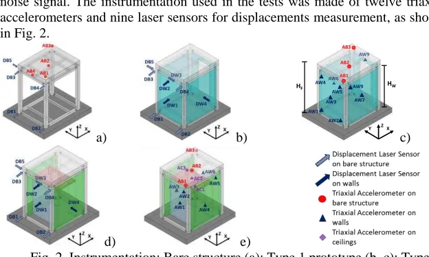
noise signal. The instrumentation used in the tests was made of twelve triaxial accelerometers and nine laser sensors for displacements measurement, as shown in Fig. 2.
a) b) c)
[image:7.612.144.456.167.354.2]d) e)
Fig. 2. Instrumentation: Bare structure (a); Type 1 prototype (b, c); Type 2 prototype (d, e).
Test results
Dynamic Identification
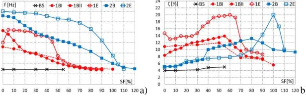
The results of dynamic identification tests were used to define the dynamic properties, namely fundamental frequency (f) and damping ratio ( ). The data of the accelerometer AB2 (Fig. 2) installed on the top mass and the recording of shake-table were used. The fundamental frequencies were calculated as the first peak of the frequency response function (or transfer function) in the frequency domain. The frequency response functions (magnitude vs. frequency curves) were obtained as the ratio between the Fourier transformation of the input signal and the response signals corresponding to the data of accelerometers installed on the top mass. The results of dynamic identification tests in terms of fundamental frequency (f) and damping ratio ( ) are given in Fig. 3a and Fig. 3b, respectively, where f and are plotted as function of scaling factor (SF). It can be noticed that the bare structure showed a constant value of fundamental frequency (2.9 Hz) and small variation of damping ratio (from 2.6% to 5.0%). As far as the influence of non-structural components on the fundamental frequency is concerned, the presence of the non-structural components increased the value of the fundamental frequency due to the increase of lateral stiffness. In addition, the decreasing of fundamental frequencies was less sudden in the case of enhanced solutions (Prototypes 1E and 2E) respect to basic solutions (Prototypes 1BI, 1BII and 2B), by showing a better seismic behaviour for the sliding connections than fixed
AB3 AB2 AB1
AW1 AW2 AW3 AW4
AW5 AW7 AW9
Y ZX
HW
connections. The presence of non-structural components altered the response also in terms of damping ratio, which increased its value respect to that recorded for the bare structure. In general, in a first phase, the damping increased when the input intensity increased, i.e. the increasing interaction between structural and non-structural components with limited damages produced an increasing of damping. In a second phase, corresponding to a significant level of damages, the damping decreased when the input intensity increased, i.e. the contribution of non-structural components became negligible for significant level of damages. However, in case of enhanced connections the damping ratio had higher variation and reached higher values (Prototypes 1E and 2E had a damping ratio in the range from 5% to 20%) than the case of basic connections (Prototypes 1BI, 1BII and 2B had a damping ratio in the range from 5% to 14%).
[image:8.612.154.462.305.403.2]a) b)
Fig. 3. Dynamic identification: a) fundamental frequency; b) damping ratio.
Floor acceleration vs inter-storey drift and observed damages
components became evident when the contact between panels and columns occurred.
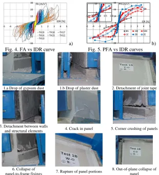
After each ICBO-AC156 input the prototype was subjected to a visual inspection mainly devoted to examine the damage caused by shake-table test. During the tests were observed damages in ceilings and both partitions and façades parallel to the X direction (shacking direction), i.e. representative of in-plane seismic response, whereas partitions parallel to the Y direction, i.e. representative of out-of-plane seismic response, did not exhibited damage. As results, the different damage phenomena observed during visual inspections have been classified for partitions and façades in eight different typologies and for ceilings in three typologies, as shown in Fig. 6 and in Fig. 7, respectively.
[image:9.612.152.462.289.630.2]a) b)
Fig. 4. FA vs IDR curve Fig. 5. PFA vs IDR curves
1.a Drop of gypsum dust 1.b Drop of plaster dust 2. Detachment of joint tape
3. Detachment between walls
and structural elements 4. Crack in panel 5. Corner crushing of panels
6. Collapse of
panel-to-frame fixings 7. Rupture of panel portions
8. Out-of-plane collapse of panel
Fig. 6. Damage typologies for partitions and façades parallel to X direction.
-30 -20 -10 0 10 20 30
-5 -4 -3 -2 -1 0 1 2 3 4 5
PFA [m/s2]
IDR [%]
BS 1BI 1BII
1E 2B 2E
-10 0 10
3. Detachment between walls and structural elements
6. Collapse of
panel-to-frame fixings 7. Rupture of panel portions Fig. 7. Damage typologies observed for ceilings.
Dynamic amplification of non-structural components
The dynamic amplification of non-structural components can be evaluated by means of the acceleration amplification factor, C, defined as the ratio between
the peak component acceleration (PCA) and peak bare structure acceleration (PBA). Note that the PBA has been evaluated as follows:
(1)
in which PIA is the maximum acceleration measured by accelerometers installed on the shacking table (peak input acceleration) and z is the vertical level of the accelerometer used to define the PCA. Fig. 8 shows the values of PCA expressed as a function of PBA, together the lines representing different values of the acceleration amplification factor ( C = 1, 1.5, 2, 3, 4). Since the tests were
unidirectional with acceleration imposed along the shaking direction, due to the orientation of the non-structural components, the obtained results are representative of out-of-plane (Fig. 8a) and in-plane (Fig. 8b) response of partitions and in-plane response of façades (Fig. 8c) and ceilings (Fig. 8d).
a) Partitions - Out of plane amplification b) Partitions - In plane amplification
From the examination of Fig. 8 it is possible to observe that the dynamic amplification increased as PBA increased. This is due to the decreasing of stiffness of non-structural components caused by the increasing of their damage. The acceleration amplification factor for out-of-plane response of partitions was in the range from 1 to 2, without significant difference between basic and enhanced connections. The dynamic amplification obtained for in-plane response of both partitions and façades is generally higher than that observed for out-of-plane response. In fact, the acceleration amplification factor for in-plane response obtained for both partitions and façades was in the range of 1 to 4, with higher values reached for enhanced connections (up to 4 for partitions and up to 3 for façades). Finally, the acceleration amplification factor for in-plane response of the ceilings was in the range of 1 to 2, with higher values (more than 1.5) obtained for enhanced connections. Therefore, the effect of different typologies of details used for connecting non-structural components to the surrounding elements was not evident in the case of out-of-plane response of partitions, whereas for all non-structural components (i.e. partitions, façades and ceilings) enhanced connections caused higher dynamic amplification than those obtained for basic connections in the case of in-plane response. As results, it can be concluded that both enhanced and basic connections offered the same degree of restrain for out-of-plane dynamic response of partitions. On contrary, enhanced connections revealed a more flexible behaviour than basic connections in terms of in-plane dynamic response of partitions, façades and ceilings.
Fragility curves for partitions and façades
The seismic response of the tested prototypes was also evaluated in terms of fragility curves. In particular, fragility curves have been developed only for the cases in which there were adequate information, i.e. partitions and façades parallel to the X direction (shacking direction), which are representative of in-plane seismic response. The evaluation of the fragility curves has been carried out according to the procedure illustrated by Porter et al., 2007. It is well known that the fragility curves are conditional probability statements of the component vulnerability, which provide the probability of reaching or exceeding a defined Damage limit State (DS) as a function of the considered Engineering Demand Parameter (EDP). In the case of in-plan seismic behaviour of partitions and façades, which are defined primarily as deformation-sensitive building components, the considered engineering demand parameter is the IDR.
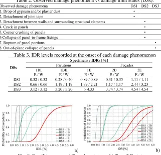
by local damage of panels and/or steel frame and requires the replacement of few elements (panels and/or local repair of steel profiles); DS3, which is characterized by severe damage and requires the replacement of significant parts or whole wall. Subsequently (step 2), the three DSs have been associated to the different damage typologies observed during the visual inspections (Table 2) (Retamales et al., 2013; Jenkins et al., 2016; Pali et al., 2018). Afterwards (step 3) the damage typologies have been associated to IDRs at which they started in the tests. In particular, Table 3 gives the minimum value for which a defined DS is triggered for each walls. From examination of Table 3 it can be noted that the seismic performance of both partitions and façades improved when enhanced anti-earthquake solutions were used. Indeed, for all examined cases, prototypes with sliding connections (1E and 2E) developed the defined DSs for IDR levels higher than prototypes with fixed connections (1BI, 1BII and 2B), by highlighting that sliding connections are effective constructional details for both partitions and façades in seismic areas. Finally (step 4), on the basis of data given in Table 3, fragility curves have been evaluated according to the method ‘A’ suggested by Porter et al., 2007, which is applicable when all prototypes failed at the observed IDRs.
In this context, it is crucial to note that a fragility curve express the damage probability of a given prototype due to the uncertainty in the system and it should be obtained considering the results of tests carried out on many nominally identical specimens. Fragility curves can be considered acceptable since they satisfy the Lilliefors goodness-of-fit test at the 5% significance level (Lilliefors 1967). As result, Fig. 9 shows the fragility curves obtained for the tested prototypes. From the examination of the obtained fragility curves, it can be confirmed that in term of seismic vulnerability the adoption of enhanced connections is more advantageous than basic connections. In fact, in prototypes with enhanced connections, the DSs are triggered for median values of the lognormal distribution greater than ones recorded for prototypes with basic connections. In particular, for both partitions and façades the median values of the lognormal distribution obtained for enhanced connections are up to about three times higher than those obtained for basic connections. As far as the comparison between partitions and façades is concerned, fragility curves show that the seismic behaviour of façades is better than that of partitions, with median values of the lognormal distribution obtained for façades higher than up to about one and a half times those obtained for partitions.
(Prototype 1E) and façades (Prototype 2E), whereas if enhanced connections are used an acceptable limit of the IDR for DS3 and DS2 could be assumed equal to 1.00%.
Table 2. Observed damage phenomena vs damage limit states (DSs).
Observed damage phenomena DS1 DS2 DS3
1. Drop of gypsum and/or plaster dust •
2. Detachment of joint tape •
3. Detachment between walls and surrounding structural elements •
4. Crack in panels •
5. Corner crushing of panels •
6 Collapse of panel-to-frame fixings •
7. Rupture of panel portions •
8. Out-of-plane collapse of panels •
Table 3. IDR levels recorded at the onset of each damage phenomenon
DSs
Specimens / IDRs [%]
Partitions Façades
1BI E / W
1BII E / W
1E E / W
2B E / W
2E E / W DS1 0.32 / 0.32 0.28 / 0.40 0.89 / 0.89 0.31 / 0.35 1.11 / 1.11 DS2 0.66 / 0.66 1.19 / 1.19 1.39 / 2.21 1.17 / 1.17 2.44 / 3.23 DS3 3.12 / 3.12 3.20 / 3.20 > 4.33 3.74 / 3.74 4.54 / 4.54
[image:13.612.146.467.202.511.2]a) b)
Fig. 9. Fragility curves: a) Type 1 prototypes b) Type 2 Prototypes
Conclusion
defined according to ICBO-AC156 Code with different levels of increasing intensity. The results of dynamic identification tests in terms of fundamental frequency and damping ratio highlighted that the presence of the non-structural components altered the response of the bare structure, by increasing both the fundamental frequency and damping ratio (up to about 5 times for both). In addition, since the damage grew as input intensity increased, the fundamental frequency decreased as input intensity increased. In particular, the decreasing of fundamental frequency was less sudden in the case of enhanced solutions by showing a better seismic behaviour for these solutions than basic solutions. The results in terms of dynamic amplification of non-structural components showed that the influence of different typologies of details used for connecting non-structural components to the surrounding elements was not evident in the case of out-of-plane response of partitions (dynamic amplification less than 2), whereas in the case of in-plane response, for all non-structural components, enhanced solutions caused higher dynamic amplification (up to 2, 3 and 4 for ceilings, façades and partitions, respectively) than that those obtained for basic solutions (dynamic amplification less than 1.5, 2 and 3 for ceilings, façades and partitions, respectively). During the tests, only for ceilings and both partitions and façades parallel to the shacking direction, i.e. representative of in-plane seismic response, were observed damages, whereas partitions perpendicular to the shacking direction, i.e. representative of out-of-plane seismic response, did not exhibited damage. The seismic response of the tested prototypes was also evaluated in terms of fragility curves only for the cases in which there were adequate information, i.e. partitions and façades parallel to the shacking direction, which are representative of in-plane seismic response. The results in terms of fragility curves showed that the adoption of enhanced solutions is more advantageous than basic solutions. In fact, in prototypes with enhanced connections, the damage limit states are triggered for median values of the lognormal distribution greater than (up to about three times) those recorded for prototypes with basic connections. As far as the comparison between partitions and façades is concerned, fragility curves show that the seismic behaviour of façades is better than that of partitions (median values of the lognormal distribution obtained for façades higher than up to about one and a half times those obtained for partitions).
Acknowledgment
acknowledged by the authors for the Consent to Publish the scientific results presented in this paper in agreement with their common research scope.
References
CEN (2005), EN 1998-1, Eurocode 8 - Design of structures for earthquake resistance - Part 1: General rules, seismic actions and rules for buildings. European Committee for Standardization, Brussels, Belgium.
CEN (2006), EN 1993-1-3, Eurocode 3 - Design of steel structures – Part 1-3: General rules - Supplementary rules for cold-formed members and sheeting. European Committee for Standardization, Brussels, Belgium.
CEN (2009), EN 10346, Continuously hot-dip coated steel flat products - Technical delivery conditions, European Committee for Standardization, Brussels, Belgium.
FEMA (2011), FEMA E-74, Reducing the risks of nonstructural earthquake damage: A practical guide. Federal Emergency Management Agency, Washington, DC.
Fiorino, L., Macillo, V., Mazzolani, F.M. 2014. Mechanical behaviour of bolt-channel joining technology for aluminium structures. Construction and
Building Materials, Volume 73, Pages 76-88. doi:
10.1016/j.conbuildmat.2014.09.086.
Fiorino, L., Herfurth, D., Hummel, H.U., Iuorio, O., Landolfo, R., Macillo, V., Pali, T., Terracciano, M.T. 2015. Out-of-plane seismic design by testing of Knauf drywall partitions. In Proceedings of the 8th International Conference on Behaviour of Steel Structures in Seismic Areas (STESSA 2015). Shanghai, China. Mazzolani F.M., Li G.-Q., Chen S., Qiang X. (eds.). Architecture & Building press. ISBN 978-7-112-18127-8. pp. 1566-1573.
Fiorino, L., Macillo, V., Landolfo, R. 2017a. Experimental characterization of quick mechanical connecting systems for cold-formed steel structures. Advances in Structural Engineering, Multi-Science. ISSN 1369-4332, Vol. 20, No. 7, pp. 1098-1110. doi:10.1177/1369433216671318
Fiorino, L., Pali, T., Bucciero, B., Macillo, V., Terracciano, M.T., Landolfo, R. 2017b. Experimental study on screwed connections for sheathed CFS structures with gypsum or cement based panels. Thin-Walled Structures, Elsevier Science. ISSN 0263-8231. Vol. 116, pp. 234-249. doi: 10.1016/j.tws.2017.03.031.
Elsevier Science. ISSN 0141-0296, Vol. 151, pp. 633–647. doi: 10.1016/j.engstruct.2017.08.056.
Fiorino, L., Shakeel, S., Macillo, V., Landolfo, R. 2018. Seismic response of CFS shear walls sheathed with nailed gypsum panels: Numerical modelling. Thin-Walled Structures, Elsevier Science. ISSN 0263-8231. Vol. 122, pp. 359-370. doi: 10.1016/j.tws.2017.10.028
International Conference of Building Officials (ICBO), 2000. ICBO AC 156 Acceptance Criteria for the Seismic Qualification of Nonstructural Components. ICBO Evaluation Service, Inc., Whittier, California, USA.
Jenkins, C., Soroushian, S., Rahmanishamsi, E., Maragakis,E.M. (2016). Experimental fragility analysis of cold-formed steel-framed partition wall systems. Thin-Walled Structures. Vol. 103. Pp. 115–127. DOI: 10.1016/j.tws.2016.02.015
Lilliefors, H. 1967. On the Kolmogorov-Smirnov test for normality with mean and variance unknown. Journal of the American Statistical Association, 62: 399-402.
Macillo, V., Fiorino, L., Landolfo, R. 2017. Seismic response of CFS shear walls sheathed with nailed gypsum panels: Experimental tests. Thin-Walled Structures, Elsevier Science. ISSN 0263-8231. Vol. 120, pp. 161-171. doi: 10.1016/j.tws.2017.08.022
Pali T, Macillo V, Terracciano MT, Bucciero B, Fiorino L, Landolfo R. 2018. In plane quasistatic cyclic tests of nonstructural lightweight steel drywall partitions for seismic performance evaluation. Earthquake Engng Struct Dyn. 2018;1–23. Doi: 10.1002/eqe.3031.
Porter, K., Kennedy, R., Bachman, R., 2007. Creating fragility functions for performance-based earthquake engineering. Earthquake Spectra; 23(2):471– 489. DOI:10.1193/1.2720892.
Restrepo, J.I., Bersofsky, A.M. 2011. Performance characteristics of light gage steel stud partition walls. Thin-Walled Structures; 49: 317–324.
Retamales, R., Davies, R., Mosqueda, G., Filiatrault, A. 2013. Experimental seismic fragility of cold-formed steel framed gypsum partition walls. Journal of structural Engineering; 139: 1285–1293. DOI: 10.1061/(ASCE)ST.1943-541X.0000657.