This is a repository copy of
Observing the Formation of Ice and Organic Crystals in Active
Sites
.
White Rose Research Online URL for this paper:
http://eprints.whiterose.ac.uk/109807/
Version: Accepted Version
Article:
Campbell, JM, Meldrum, FC orcid.org/0000-0001-9243-8517 and Christenson, HK
orcid.org/0000-0002-7648-959X (2017) Observing the Formation of Ice and Organic
Crystals in Active Sites. Proceedings of the National Academy of Sciences, 114 (5). pp.
810-815. ISSN 1091-6490
https://doi.org/10.1073/pnas.1617717114
© 2016, National Academy of Sciences . This is an author produced version of a paper
published in Proceedings of the National Academy of Sciences. Uploaded in accordance
with the publisher's self-archiving policy. In order to comply with the publisher requirements
the University does not require the author to sign a non-exclusive licence for this paper.
[email protected] https://eprints.whiterose.ac.uk/ Reuse
Items deposited in White Rose Research Online are protected by copyright, with all rights reserved unless indicated otherwise. They may be downloaded and/or printed for private study, or other acts as permitted by national copyright laws. The publisher or other rights holders may allow further reproduction and re-use of the full text version. This is indicated by the licence information on the White Rose Research Online record for the item.
Takedown
If you consider content in White Rose Research Online to be in breach of UK law, please notify us by
1
Observing the Formation of Ice and Organic Crystals in Active Sites
James M. Campbell
1, Fiona C. Meldrum
2and Hugo K. Christenson
11School of Physics and Astronomy, University of Leeds, Leeds, LS2 9JT, United Kingdom
2School of Chemistry, University of Leeds, Woodhouse Lane, Leeds, LS2 9JT, United Kingdom.
Corresponding author: Hugo Christenson, School of Physics and Astronomy, University of Leeds, Woodhouse Lane, Leeds, LS2 9JT, UK. 0113 343 3879, [email protected].
PHYSICAL SCIENCES: Applied Physical Sciences
2
Abstract
Heterogeneous nucleation is vital to a wide range of areas as diverse as ice nucleation on atmospheric
aerosols and the fabrication of high-performance thin films. There is excellent evidence that surface
topography is a key factor in directing crystallisation in real systems, however the mechanisms by
which nanoscale pits and pores promote nucleation remain unclear. Here, we use natural cleavage
defects on Muscovite mica to investigate the activity of topographical features in the nucleation from
vapour of ice and various organic crystals. Direct observation of crystallisation within surface pockets
using optical microscopy, and also interferometry, both demonstrate that these sharply acute features
provide extremely effective nucleation sites, and allows us to determine the mechanism by which this
occurs. A confined phase is first seen to form along the apex of the wedge, and then grows out of the
pocket opening to generate a bulk crystal after a threshold saturation has been achieved. Ice
nucleation proceeds in a comparable manner, although our resolution is insufficient to directly
observe a condensate prior to the growth of a bulk crystal. These results provide new insight into the
mechanism of crystal deposition from vapour on real surfaces, where this will ultimately enable us to
use topography to control crystal deposition on surfaces. They are also particularly relevant to our
understanding of processes such as cirrus cloud formation, where such topographical features are
atmosphere.
Significance Statement
Crystal nucleation - the first appearance of a crystalline phase where there was none before - usually
occurs at the surface of a foreign material. Ice formation in the atmosphere is dependent upon the
number and type of aerosol particles present, but little is known about why some are more effective
than others. Here we investigate the role of surface topography in promoting crystallisation of ice and
different organic crystals and show that acute geometries are highly effective in promoting the growth
of a confined crystalline phase, which then gives rise to a bulk phase. This is relevant to crystallisation
in a large number of real world systems such as industrial film growth and our climate.
3
Introduction
The growth of a new phase is almost always dependent on a nucleation event. Nucleation is therefore
fundamental to a number of processes including crystallisation, freezing, condensation and bubble
formation and is typically described in terms of classical nucleation theory. However, as this theory
was developed to describe the nucleation of liquid droplets in vapour, it cannot give a complete
understanding of all nucleation processes, and in particular the formation of crystalline materials.
Nucleation in the real world is also usually heterogeneous, occurring on seeds, impurities, or container
surfaces. Although simple models consider nucleation to occur on perfectly flat, uniform surfaces, it
is clear that real surfaces inevitably vary in chemistry and topography. We focus here on the effects
of surface topography. Classical nucleation theory predicts a lower free energy barrier to nucleation
in surface cracks or pores on the length scale of a critical nucleus.(1) The extent of the reduction is
contact-angle dependent, such that nuclei with a low contact angle experience a more significant
reduction from topography.
Topography is known to promote crystallisation directly from a vapour (2-5), as these systems typically
exhibit low contact angles. Crystallisation from the melt, in contrast, is associated with very high
contact angles such that topography is usually ineffective (6). Crystallisation from solution provides
an intermediate case, and has perhaps received the most attention. Roughened surfaces have been
shown to enhance the nucleation of a range of crystals (7-10), while the nucleation of proteins and
organic crystals is promoted within narrow pores of specific diameters.(11-13) The geometries of
these pores can even determine the orientation and polymorphs of the product crystals.(14-16)
However, while these data provide strong evidence for the importance of surface topography to
nucleation, we still have little knowledge of what makes a good nucleation site, or how such sites
function on the nanoscale.
One area where these questions have been considered is atmospheric ice nucleation. It has been
suggested that surfaces could exhibit a small number of "active sites" which determine the nucleating
ability of an entire surface.(17-19) Each site has its own threshold supersaturation or supercooling
above which nucleation becomes probable,(20, 21) and the sites with the lowest thresholds dominate.
Fukuta then suggested that ice nucleation from vapour may proceed by the formation of confined
condensates within small pores and cracks, and that bulk crystals emerge from these upon sufficient
saturation of water vapour.(22) To understand heterogeneous nucleation, we therefore need to
4
The current study addresses this challenge by investigating the nucleation from vapour of ice and a
number of organic compounds within a well-defined topographical feature
commonly formed along the steps on cleaved mica substrates. Featuring a highly acute wedge
geometry, these structures are possible candidates for the active sites present on clay/dust particles
that drive atmospheric ice nucleation. Importantly, we can use optical microscopy to both
characterise the geometry of these pockets and to monitor crystallisation in situ within them. Our
results show that the mica pockets are extremely effective nucleation sites for every compound we
have exposed them to. We also provide direct experimental evidence for a condensate-mediated
method of nucleation, where growth originates as a confined condensate along the apex of an acute
5
Results
Substrates were prepared by cleaving Muscovite mica, which generates a pristine surface that is
atomically flat over large areas (23). These surfaces often feature a number of step edges, which can
themselves support a range of defects. The current study exploits one key type of defect, namely the
a space in-between (Figure 1). A highly acute wedge geometry is formed where the two mica surfaces
meet that would be impossible to generate using surface engineering techniques. Importantly, these
pockets can be readily studied using optical interference, where the pattern of interference fringes
provides information about the separation of the mica sheets at different positions within the pockets
(Figure 1). Interference between reflections from the mica surfaces forming the top and bottom of
the wedge produces a reflected light intensity that is dependent on the mica-mica spacing as
described by the relation
z
a
I
I
0
sin
22
(1)where is the wavelength, is a background intensity from other surfaces and a constant
dependent on the reflectance (more details and exact form in Supplementary Information). As a
consequence there is a bright fringe at separation and then at intervals of . This allows a
wedge profile to be precisely calculated. The pattern of these fringes also changes on deposition of
liquid or solid within the pocket, such that we can monitor the entire growth sequence of crystals
within these features. The presence of a condensed phase greatly reduces the reflectance of both
surfaces, making drop almost to . With the additional ease of diffusion of material into these
features, they are ideal for studying topographically aided nucleation.
Three organic compounds norbornane, carbon tetrabromide and camphor were selected for study
as they have high vapour pressures and melting points well above room temperature (23-25 °C), with
their physical properties presented in Supplementary Table S1. Preliminary experiments were also
conducted with hexachloroethane, hexamethylcyclotrisiloxane and tetramethylbutane. These
experiments were performed in a sealed cell that contains a reservoir of crystal at the base and the
mica substrate at the top, where the mica can be observed throughout the experiment using an optical
microscope in reflected light mode.(19) Saturation is controlled by adjusting the temperature of the
reservoir with respect to that of the substrate, which is held at room temperature. The reservoir is
initially cooled to 1 °C below the substrate to produce undersaturated conditions. This protocol
6
moment of first emergence of a bulk crystal from the pocket (see Methods in the Supplementary
Information).
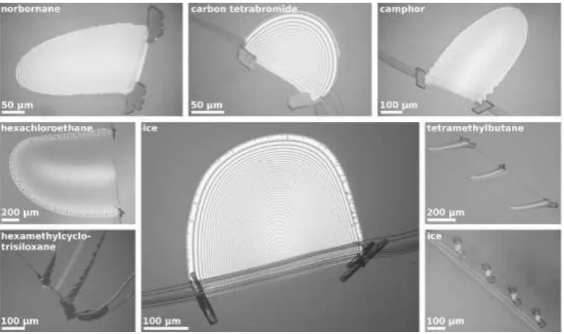
The mica pockets provide extremely effective nucleation sites for every organic compound we studied.
A distinctive pattern of growth was observed, in which twin crystals grow from the two "corners" of
the pocket where the wedge apex meets the step edge (Figure 2). Crystal growth is also seen all along
the apex of the wedge in each case, although this is sometimes difficult to see in low-magnification
images. Figures 3a-d show high-magnification images of a norbornane condensate near to a corner
(camphor and carbon tetrabromide results are qualitatively similar). A condensate begins to form in
the wedge apex and then grows steadily, tending to grow thicker close to the corner, consistent with
a lower diffusion barrier to growth near the corner.(24) For every organic compound, a condensate is
clearly visible before a bulk crystal emerges from the pocket corner.
Ice nucleation was studied at temperatures down to -45.0 °C in a different cell (Materials and
Methods, Supplementary Information), and experiments were performed by reducing the substrate
temperature at 0.25 °C min-1 while exposed to gas flow with a steady and adjustable humidity. At
nucleation temperatures of -37.0 °C and above the pocket appears to be unimportant, with liquid
drops condensing on the mica surface, some of which then freeze and hence cause the others to
evaporate. At -38.8 °C and below, the same mode of growth was seen as with the organics, with
hexagonal or columnar ice crystals emerging from the pocket corners (Figure 2). But unlike the
organics, no condensate was ever observed before the appearance of a bulk crystal, down to the
observation limit of 15 nm. Figures 3e,f show the growth of ice crystals along a wedge apex at -39.0
°C, but this growth was not seen until just after the first bulk crystal growth was observed at the
corner. Saturation could not be so precisely quantified as with organics, but ice was seen emerging
from the pockets at a saturation of 1.2 ± 0.1 for all experiments.
T ondensates were quantified by taking an intensity profile across an
interference fringe and finding the location of a sharp step in intensity from the condensate edge, as
illustrated in Figures 1f-1h. This method is accurate to within 1 nm for condensates as small as 15 nm;
smaller condensates cannot usually be unambiguously detected. The heights of condensates formed
prior to the emergence of a bulk crystal are plotted in Figures 4 and 5. Norbornane condensates form
in the wedge even in undersaturated conditions (Figure 5), while no evidence for the existence of
7
However, as these compounds have much lower vapour pressures than norbornane, their
condensates would take longer to grow to an observable size.
This possibility was investigated further by performing experiments in which the saturations of carbon
tetrabromide and camphor were allowed to approach (but never quite reach) unity slowly over several
hours. The carbon tetrabromide condensate grew to 84 ± 1 nm after three hours, while that of
camphor grew to 60 ± 1 nm after five hours. The influence of the temperature ramp rate on the
condensation of norbornane within a single pocket was also studied (Figure 5) and showed two clear
trends as the ramp rate increases: a higher saturation is required before bulk crystals emerge; and the
precursor condensates are smaller in size.
Further information about the mechanism of crystallisation was obtained by performing multiple
crystallisation cycles using the same mica pockets, where the cell was flushed after each run to sublime
the previous crystals (in the case of ice the substrate was warmed to above 0 °C between runs). For
both the organics and ice, the two bulk crystals that form at each side of a pocket were seldom in the
same crystallographic orientation, as judged by their external geometries. This demonstrates that the
two external crystals and connecting condensate are rarely a single crystal. There was also no
evidence of a consistent orientation between runs, suggesting that the geometry of the wedge does
8
Discussion
Our results provide a striking demonstration that surface topography and in particular features
containing narrow wedges can provide extremely effective nucleation sites, where the organic
compounds studied initially deposit in the apex of the mica wedge, before growing out of the pockets
as bulk crystals. The deposition of a condensed phase, be it liquid or solid, within the pockets is driven
by the lower interfacial free energy between the mica substrate and the condensate compared to the
interfacial free energy between the mica and the vapour. As a consequence the condensate has a
contact angle below 90° and may form a concave interface, as shown in Figure 1f. The Kelvin equation
describes a reduction of vapour pressure over a curved interface:
rRT V p p m 0 cos '
ln
(2)where is the vapour pressure over a flat surface, is the contact angle of the substance in the
condensate on mica, is the compound-vapour surface free energy, m is the molar volume, is the
radius of curvature of the interface condensate, is the gas constant and is the temperature. For
a condensate interface that is concave towards the vapour is negative, and therefore the vapour
pressure is reduced below that for a flat surface. Thus, any substance can condense in an acute wedge
slightly below saturation, provided that is below 90°, which is known as capillary condensation. The
largest condensates will occur when approaches 0°, which in our case means that , the
condensate height.
We expect the first condensate formed to be a supercooled liquid, which will then freeze to form a
solid condensate by normal nucleation. The Gibbs-Thomson effect predicts that a confined phase will
suffer a decrease in the melting point inversely proportional to the dimension of the pore; as such, an
infinitesimally small condensate is expected to be a liquid.(25) This mechanism has been
experimentally observed in a highly acute annular wedge.(24-26)
Theoretically, the size of a supercooled liquid condensate is described by the Clausius-Clapeyron
relation, which shows that the vapour pressure over a supercooled liquid is higher than over a
solid at the same temperature:
mfus
1
1
ln
T
T
R
H
p
p
s l (3)where is the enthalpy of fusion and m the melting point. This predicts a ratio / of 1.5 for
water/ice at -40 °C, of 1.3 for both norbornane and carbon tetrabromide and of 2.5 for camphor at 27
9
the same conditions. The height of a liquid condensate, assuming , at solid saturation may be
estimated by combining equations 2 and 3:
m fus mm
2
1
1
T
T
H
hT
V
rT
V
(4)where here refers to liquid-vapour surface tension. At this is only approximate (25). Values
of are predicted in Table 1.
Following this argument, are the condensates that we here observe supercooled liquids or solids?
Figure 5 shows the estimated equilibrium heights of solid and liquid norbornane condensates,
assuming = 0°. These lines give the maximum sizes these condensates could reach if they were left
sufficiently long to equilibrate at any given saturation. The observed condensate heights are well
above those possible for a liquid condensate, which provides conclusive evidence that the measured
condensates are solid. As Table 1 shows, the expected height of the liquid condensates at saturation
with respect to solid are below or close to the lower limit of observation for all compounds. However,
this does not rule out the initial presence of a supercooled liquid condensate which then freezes to
give rise to a solid condensate before the condensate grows to an observable size. Estimation of the
critical nucleus radius for all of our systems (Table 1) shows that the condensate heights are more than
twice the critical radii; liquid condensates of this size are large enough to contain a critical nucleus and
are therefore metastable with respect to freezing.
So far we have discussed only the formation of a condensate inside a wedge without considering the
transition into a bulk phase. As seen in Figures 3a-d, the confined condensate extends right to the
pocket corner where it meets the bulk vapour. There seems to be nothing stopping the crystal from
growing out into the bulk, and yet no emergence is observed until a threshold supersaturation is
attained. This problem is illustrated in Figure 6, in which the condensate has a concave interface,
provided that is below 90°. However, as it begins to bulge out of the narrow opening, it first flattens
out and its curvature then becomes convex with respect to the vapour and passes through a minimum
in radius of curvature. After this point it can grow unrestricted into the bulk phase. In equation 2,
changes sign, necessitating a supersaturated vapour. The minimum in the convex radius of curvature
defines a minimum or threshold supersaturation necessary for the condensate to emerge from the
pore. Taking this minimum radius to be equal to the pore radius, the threshold saturation is given
10
rRT
V
S
mln
(5)It follows that the narrower the mica-mica separation at the pore opening, the higher the saturation
needed for a bulk phase to emerge. This concept has been verified in simulations by Page and Sear,(27)
who show that there is a free energy barrier for a crystal to emerge from a narrow pore, which does
not exist if the saturation is sufficiently high.
While this is clearly a simplified model of our system, it works well to illustrate general trends. The
edge of our system can be seen as a slit pore which increases in width with increasing distance from
the wedge apex. When a condensate is very small, the mica-mica spacing is too narrow for it to
emerge at modest supersaturation (the energy barrier is too large). As the supersaturation increases,
the condensate grows further from the apex such that the width of the gap from which the condensate
must emerge also increases. At some point the saturation exceeds the threshold for growth through
the gap, and a bulk crystal emerges. The threshold lines for camphor and carbon tetrabromide, and
for norbornane are shown in Figures 4 and 5, respectively. While our data are in good agreement with
these at low rates of saturation increase, at the higher rates used with norbornane the condensate
size and saturation increase significantly beyond the point where emergence would be expected.
However, at high rates of crystal growth it is likely that the local supersaturation is no longer accurately
given by the temperature difference between substrate and reservoir.
In the case of ice, no condensates were seen prior to the growth of bulk crystals. Rather than implying
that there were no condensates, it is extremely likely that the condensates were simply too small to
observe (below 15 nm) up to the moment of bulk emergence. The nature of growth, with two crystals
at the pocket corners and a continuous line of crystal growth along the wedge apex, is strikingly
reminiscent of results with organic compounds where condensates were observed prior to growth
(Figure 2). Ice at -40 °C has a significantly lower vapour pressure than any of the other compounds
studied, and the ramp rate into supersaturated conditions was faster, so observably large ice
condensates may not have had sufficient time to form. Equation 5 predicts that a 15 nm ice
condensate could emerge into a bulk phase at a modest saturation of 1.13, so if this saturation was
attained before the condensates grew to visible size, we would not expect further growth before the
appearance of a bulk crystal. It is also possible that the condensate was supercooled water, which on
freezing would begin to grow all along the wedge apex at the same time as the bulk crystal emerges,
as was observed. As seen in Table 1, the water condensate would be below the 15 nm limit of
11
with a constant 0.3° angle and extrapolating published ice nucleation rates (28), we estimate that we
would expect to see one nucleation event every 1.2 minutes at -39 °C. On the time-scale of these
experiments (a ramp rate of 0.25 °C/min) it is plausible that ice nucleation from water is the limiting
step in the process.
The results with ice are immediately relevant to atmospheric ice nucleation on solid aerosol particles.
Most studies of atmospheric ice nucleation have focused on the importance of surface chemistry and
lattice matching. However, the correlation between lattice match and nucleation is in general not
strong,(29) and there is a wide scatter in the reported nucleating abilities of atmospheric aerosols (30).
The mechanism of ice nucleation in capillary-condensed water that was proposed fifty years ago by
Fukuta has only recently been re-visited (31, 32), but it has already been suggested that it contributes
to the ice nucleation capacity of kaolinite (33, 34), and leads to enhanced ice nucleation by porous
aerosol particles (35, 36). It is also noteworthy that alkali feldspars, which have been shown to be
particularly efficient ice nucleators (37) usually have a rich microstructure (38) with an abundance of
sites where water might condense. We have now directly observed how nucleation via condensed,
supercooled water is an important mechanism for nucleation of ice in cleavage defects on mica,
12
Conclusions
These results provide direct experimental evidence that highly acute wedges the key feature of the
mica pockets studied here are extremely effective nucleation sites for crystallisation from vapour.
Using direct imaging approaches we demonstrate that bulk crystals form subsequent to generation of
a confined condensate in the acute wedge, where this can even occur in undersaturated conditions.
Although we employed micron-scale topographical features for the purpose of easy and unambiguous
condensate observation, the principles should equally apply to smaller features that may occur on
natural or engineered surfaces. The only compulsory feature is that they must possess a geometry
acute enough to allow condensation without an energy barrier. This model also suggests that there
will be an optimal feature size for any given supersaturation. Features which are too small may fill
quickly but have too narrow an opening to allow emergence into a bulk phase. Conversely, large
features may take so long to fill that crystals may have already emerged from smaller features. This
phenomenon clearly has many real-world applications. Crystal nucleation from vapour is a vital
process in atmospheric science and in technological applications such as Chemical Vapour Deposition
film growth. An analogous thermodynamic pathway to nucleation has even been proposed to occur
in solution during the formation of biominerals such as calcium carbonate from amorphous precursor
phases.(39) Understanding topographically-directed crystallisation, and identification of the most
active features, therefore promises a novel strategy for controlling nucleation in a wide range of
environments.
Acknowledgements
HKC acknowledges a grant from the Leverhulme Trust (RPG-2014-306), and HKC and FCM
13
References
1.
Sholl CA & Fletcher NH (1970) Decoration criteria for surface steps. Acta
Metall 18(10):1083-1086.
2.
Buijnsters JG, Vázquez L, & Ter Meulen JJ (2009) Substrate pre-treatment by
ultrasonication with diamond powder mixtures for nucleation enhancement in
diamond film growth. Diam Relat Mater 18(10):1239-1246.
3.
Dennig PA & Stevenson DA (1991) Influence of substrate topography on the
nucleation of diamond thin films. Appl Phys Lett 59(13):1562-1564.
4.
Portavoce A, Kammler M, Hull R, Reuter MC, & Ross FM (2006) Mechanism
of the nanoscale localization of Ge quantum dot nucleation on focused ion
beam templated Si(001) surfaces. Nanotechnology 17(17):4451.
5.
Holbrough JL, Campbell JM, Meldrum FC, & Christenson HK (2012)
Topographical control of crystal nucleation. Cryst Growth Des 12(2):750-755.
6.
Campbell JM, Meldrum FC, & Christenson HK (2015) Is ice nucleation from
supercooled water insensitive to surface roughness? J Phys Chem C
119(2):1164-1169.
7.
Diao Y, Myerson AS, Hatton TA, & Trout BL (2011) Surface design for
controlled crystallization: The role of surface chemistry and nanoscale pores
in heterogeneous nucleation. Langmuir 27(9):5324-5334.
8.
Sengupta Ghatak A & Ghatak A (2013) Disordered nanowrinkle substrates for
inducing crystallization over a wide range of concentration of protein and
precipitant. Langmuir 29(13):4373-4380.
9.
Järn M, Areva S, Pore V, Peltonen J, & Linden M (2006) Topography and
surface energy dependent calcium phosphate formation on sol-gel derived
TiO
2coatings. Langmuir 22(19):8209-8213.
10.
Asanithi P (2014) Surface porosity and roughness of micrographite film for
nucleation of hydroxyapatite. J Biomed Mater Res-A 102(8):2590-2599.
11.
Ha J-M, Wolf JH, Hillmyer MA, & Ward MD (2004) Polymorph selectivity
under nanoscopic confinement. J Am Chem Soc 126(11):3382-3383.
12.
Chayen NE, Saridakis E, & Sear RP (2006) Experiment and theory for
heterogeneous nucleation of protein crystals in a porous medium. P Natl Acad
Sci USA 103(3):597-601.
13.
Shah UV, Williams DR, & Heng JYY (2012) Selective crystallization of
proteins using engineered nanonucleants. Cryst Growth Des
12(3):1362-1369.
14.
Diao Y, Harada T, Myerson AS, Hatton TA, & Trout BL (2011) The role of
nanopore shape in surface-induced crystallization. Nat Mater 10(11):867-871.
15.
Mitchell CA, Yu L, & Ward MD (2001) Selective nucleation and discovery of
organic polymorphs through epitaxy with single crystal substrates. J Am
Chem Soc 123(44):10830-10839.
14
17.
Fletcher NH (1969) Active sites and ice crystal nucleation. J Atmos Sci
26(6):1266-1271.
18.
Niedermeier D, et al. (2011) Heterogeneous ice nucleation: exploring the
transition from stochastic to singular freezing behavior. Atmos Chem Phys
11(16):8767-8775.
19.
Campbell JM, Meldrum FC, & Christenson HK (2013) Characterization of
preferred crystal nucleation sites on mica surfaces. Cryst Growth Des
13(5):1915-1925.
20.
Dorsey NE (1938) Supercooling and freezing of water. J Res Natl Bureau
Standards 20(6):799-808.
21.
Vali G (2014) Interpretation of freezing nucleation experiments: singular and
stochastic; sites and surfaces. Atmos Chem Phys 14(11):5271-5294.
22.
Fukuta N (1966) Activation of atmospheric particles as ice nuclei in cold and
dry air. J Atmos Sci 23(6):741-750.
23.
Christenson HK & Thomson NH (2016) The nature of the air-cleaved mica
surface. Surf Sci Rep 71(2):367-390.
24.
Kovács T & Christenson HK (2012) A two-step mechanism for crystal
nucleation without supersaturation. Faraday Discuss 159(1):123-138.
25.
Nowak D, Heuberger M, Zäch M, & Christenson HK (2008) Thermodynamic
and kinetic supercooling of liquid in a wedge pore. J Chem Phys
129(15):154509.
26.
Kovács T, Meldrum FC, & Christenson HK (2012) Crystal nucleation without
supersaturation. J Phys Chem Lett 3(12):1602-1606.
27.
Page AJ & Sear RP (2006) Heterogeneous nucleation in and out of pores.
Phys Rev Lett 97(6):065701.
28.
Murray BJ, et al. (2010) Kinetics of the homogeneous freezing of water. Phys
Chem Chem Phys 12(35):10380-10387.
29.
Conrad P, Ewing GE, Karlinsey RL, & Sadtchenko V (2005) Ice nucleation on
BaF
2(111). J Chem Phys 122(6):064709-064709.
30.
Hoose C & Möhler O (2012) Heterogeneous ice nucleation on atmospheric
aerosols: a review of results from laboratory experiments. Atmos Chem Phys
12(20):9817-9854.
31.
Christenson HK (2013) Two-step crystal nucleation via capillary condensation.
Cryst Eng Comm 15(11):2030-2039.
32.
Marcolli C (2014) Deposition nucleation viewed as homogeneous or
immersion freezing in pores and cavities. Atmos Chem Phys
14(4):2071-2104.
33.
Welti A, Kanji ZA, Lüönd F, Stetzer O, & Lohmann U (2014) Exploring the
mechanisms of ice nucleation on kaolinite: from deposition nucleation to
condensation freezing. J Atmos Sci 71(1):16-36.
15
35.
Adler G, et al. (2013) Formation of highly porous aerosol particles by
atmospheric freeze-drying in ice clouds. P Natl Acad Sci USA
110(51):20414-20419.
36.
Wagner R, Kiselev A, Möhler O, Saathoff H, & Steinke I (2016) Pre-activation
of ice-nucleating particles by the pore condensation and freezing mechanism.
Atmos Chem Phys 16(4):2025-2042.
37.
Yakobi-Hancock JD, Ladino LA, & Abbatt JPD (2013) Feldspar minerals as
efficient deposition ice nuclei. Atmos Chem Phys 13(22):11175-11185.
38.
Parsons I, Lee MR, & Smith JV (1998) Biochemical evolution II: Origin of life
in tubular microstructures on weathered feldspar surfaces. P Natl Acad Sci
USA 95(26):15173-15176.
39.
Stephens CJ, Ladden SF, Meldrum FC, & Christenson HK (2010) Amorphous
calcium carbonate is stabilized in confinement. Adv Funct Mater
20(13):2108-2115.
40.
Bailey AI & Kay SM (1965) Measurement of refractive index and dispersion of
mica, employing multiple beam interference techniques. Brit J Appl Phys
16(1):39.
41.
Hacker PT (1951) Experimental values of the surface tension of supercooled
water (National Advisory Committee for Aeronautics).
42.
Hillig WB (1998) Measurement of interfacial free energy for ice/water system.
J Cryst Growth 183(3):463-468.
43.
Böyük U & Maraşlı N (2009) Interfacial energies of carbon tetrabromide.
Curr
Appl Phys 9(2):359-366.
44.
Haynes WM (2016) CRC handbook of chemistry and physics (CRC press).
45.
Boublík T, Fried V, & Hála E (1984) The vapour pressures of pure substances
(Elsevier).
46.
Bradley RS & Drury T (1959) The vapour pressure and lattice energy of
carbon tetrabromide. T Faraday Soc 55:1844-1847.
47.
Murphy DM & Koop T (2005) Review of the vapour pressures of ice and
supercooled water for atmospheric applications. Q J Roy Meteor Soc
131(608):1539-1565.
48.
Boyd RH, Sanwal SN, Shary-Tehrany S, & McNally D (1971)
Thermochemistry, thermodynamic functions, and molecular structures of
some cyclic hydrocarbons. J Phys Chem 75(9):1264-1271.
49.
Rietveld IB, et al. (2010) Temperature and composition-dependent properties
of the two-component system d-and l-
camphor at ‘ordinary’pressure.
Thermochim Acta 511(1):43-50.
50.
Yaws CL & Gabbula C (2003) Yaws' Handbook of Thermodynamic and
Physical Properties of Chemical Compounds (Knovel).
51.
Feistel R & Wagner W (2007) Sublimation pressure and sublimation enthalpy
of H
2O ice I
hbetween 0 and 273.16 K. Geochim Cosmochim Ac 71(1):36-45.
16
53.
Weast RC (1987) CRC Handbook of Chemistry and Physics (CRC Press).
17
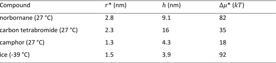
Table 1. Classical nucleation theory predictions for size of critical nucleus radius ( *) and free energy barrier ( *). is the predicted size of a liquid condensate at saturation with respect to a solid.
Compound * (nm) (nm) * ( )
norbornane (27 °C) 2.8 9.1 82
carbon tetrabromide (27 °C) 2.3 16 35
camphor (27 °C) 1.3 4.3 18
18
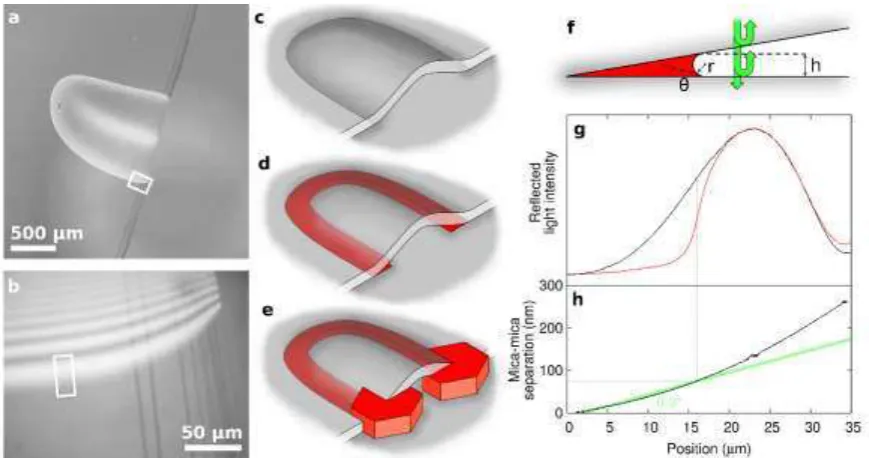
Figure 1. Experimental overview. (a) Optical micrograph of a pocket, and (b) a higher-magnification
view of the region outlined in white, showing interference fringes. (c) Schematic illustration of a
pocket, and (d) and (e) the growth of a crystalline condensate (in red) which then leads to the growth
of twin bulk crystals. (f) A condensate forming in an acute wedge, where the twin reflections of light
from closely-spaced mica surfaces (green arrows) leads to interference fringes; also showing
condensate height , interface radius of curvature and contact angle . (g) Light intensity curves
across a single fringe highlighted in white in (b), corresponding to an empty wedge (black) and a wedge
holding a 75 nm condensate of carbon tetrabromide (red). The condensate is visible as a relatively
sharp cut-off of fringe intensity. (h) The wedge profile calculated from the black curve in (g), with a
19
Figure 2. Optical micrographs showing crystals of various compounds crystallising from the two
[image:20.595.93.505.70.314.2]20
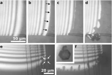
Figure 3. Optical micrographs showing crystal nucleation of norbornane (a-d, pocket opening at
bottom of images) and ice (e-f, pocket opening at right of images) in the corners of mica pockets.
Where a condensate exists it is visible as a sharp step in reflected light intensity, in contrast to the
gradual transition associated with an empty wedge. Norbornane: (a) empty wedge, (b) small
condensate below high (indicated by black arrows), (c) larger condensate just before emergence
of a bulk crystal, and (d) after emergence of a bulk crystal. Ice (at -39.0 °C): (e) the white arrows
indicate the first appearance of an ice crystal at the pocket corner, with no condensate yet visible
along the wedge apex; (f) subsequent growth of ice along the wedge apex. The inset shows a
[image:21.595.108.490.97.352.2]21
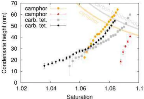
Figure 4. Graphs of condensate size with increasing saturation (with respect to bulk solid) for camphor
and carbon tetrabromide at a ramp rate of 0.1 °C min-1. The first point in each series marks the first
unambiguously detectable condensate, while the last marks the first appearance of a bulk crystal
emerging from the pocket corner. Error bars represent standard error in measurement of condensate
heights; horizontal error bars are omitted for clarity. The grey and orange lines predict the condensate
size above which there should be no barrier to emergence into a bulk crystal for carbon tetrabromide
22
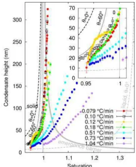
Figure 5. Graphs of norbornane condensate size with increasing saturation (with respect to bulk solid).
The first point in each series marks the first unambiguously detectable condensate; the last marks the
first appearance of a bulk crystal emerging from the pocket corner. The circles show growth at various
temperature ramp rates in the same mica pocket, while open black squares show growth in a different
pocket at 0.1 °C min-1. The inset is an enlargement of the bottom-left region of the main graph. Error
bars (often too small to be visible) represent standard error in measurement of condensate heights;
horizontal error bars are omitted for clarity. The dashed lines show the predicted equilibrium
condensate size for a solid and a liquid (black and grey respectively). The thick grey line predicts the
23
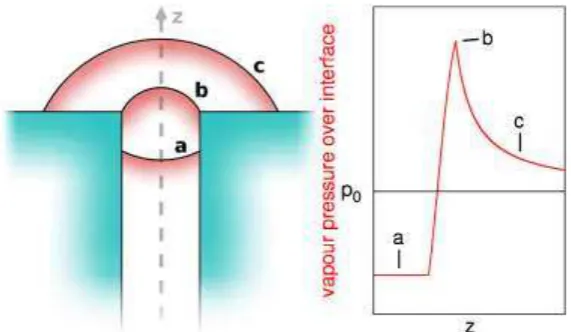
Figure 6. (left) Illustration of how a phase confined in a pore emerges into a bulk phase. (a) The phase
initially has a concave interface, allowing it to be stable in confinement even in undersaturated
conditions. (b) Before it can emerge into a bulk phase it must briefly form a highly convex interface,
requiring supersaturation. (c) As the bulk phase grows its interface curvature reduces, tending towards
a planar interface. (right) Schematic graph of the evolution of vapour pressure over the interface as
the new phase emerges, with the labels a, b and c corresponding to the three stages illustrated on the