UNIVERSITI TEKNIKAL MALAYSIA MELAKA
OPTIMIZATION AND ANALYZE OF FIXABLE CLAMPING JIG
FOR MILLING MACHINE
This report submitted in accordance with requirement of the Universiti Teknikal Malaysia Melaka (UTeM) for the Bachelor Degree of Engineering Technology
(Process and Technology) (Hons.)
by
AZIZI ARIF BIN ONN B071410335 950106016211
i
DECLARATION
I hereby, declared this report entitled “Optimization and Analyze of Fixable Clamping Jig for Milling Machine” is the results of my own research except as cited
in references.
Signature : ………. Author’s Name : AZIZI ARIF BIN ONN
ii
APPROVAL
This report is submitted to the Faculty of Engineering Technology of UTeM as a partial fulfillment of the requirements for the degree of Bachelor Degree of Engineering Technology (Process and Technology) with Honours. The member of the supervisory is as follow:
iii
ABSTRAK
iv
ABSTRACT
v
DEDICATION
To my beloved family especially my father and mother, En. Onn Bin Pangkat and Pn. Norzanar Binti Samsuri, I would to express my appreciation to my parents for their continuous support to me in performing this difficult task, and the journey does not
end here.
To my supervisor, Dr. Norfariza Binti Ab. Wahab and Encik Khahar Bin Nordin for being receptive and critical, and challenging me to be a better student.
vi
ACKNOWLEDGEMENT
Bismillahirrahmanirrahim.
Thanks to Allah SWT, whom with His willing giving me the opportunity to complete this Final Year Project.
First and foremost, I would like to express my sincere appreciation to my supervisor, Dr. Norfariza Binti Ab. Wahab and Encik Khahar Bin Nordin, for
constantly guiding and encouraging me throughout this study. Thanks a lot for giving me a professional training, advice and suggestion to bring this project to its final form.
In particular, my sincere thankful is also extends to all my colleagues and others who have provided assistance at various occasions. Their views and tips are useful indeed. I am also obliged to express my appreciation towards my parents and also my family members for their enduring patience, moral and financial supports.
vii
TABLE OF CONTENTS
DECLARATION i
APPROVAL ii
ABSTRAK iii
ABSTRACT iv
DEDICATION v
ACKNOWLEDGEMENT vi
TABLE OF CONTENTS vii
LIST OF TABLES x
LIST OF FIGURES xi
CHAPTER 1 1
INTRODUCTION 1
1.1 Background 1
1.2 Problem Statement 2
1.3 Objective 4
1.4 Scope 4
CHAPTER 2 5
LITERATURE REVIEW 5
2.1 Introduction of Machining Process 5
2.1.1 Conventional Machining 5
2.1.1.1 Milling Machine 6
2.1.1.2 Turning Machine 8
2.1.1.3 Drilling Machine 9
2.1.1.4Type of Drilling 10
2.1.1.4.1 Bench Drill 10
2.1.1.4.2 Hand Drill 10
2.1.1.4.3 Radial Drill 11
2.1.2 Advance Machining 12
viii 2.1.2.2 Electrochemical Machining (ECM) 12 2.1.2.3 Electron Beam Machining (EBM). 13
2.1.2.3 CNC Machining 13
2.2 Milling Machine 14
2.2.1 Convectional milling or Up cut milling 15 2.2.2 Climb cut milling or down cut milling 16
2.3 Milling Machine Vices 16
2.4 Cutting Parameters 18
2.4.1 Cutting Speed 18
2.4.2 Feed Rate 19
2.4.3 Depth of Cut 19
2.5 Force 20
CHAPTER 3 21
METHODOLOGY 21
3.0 Introduction 21
3.1 Optimization of Design 26
3.1.1 Part 1 (Clamping Vice) 26
3.1.2 Part 2 (Base) 28
3.1.3 Material Selection 29
3.2 Optimization of the Result 30
3.3 Analyze of Result 31
CHAPTER 4 32
RESULT AND DISCUSSION 32
4.0 Introduction 32
4.1 Finish Optimization Product Overview 32 4.2 Optimization Product and Process. 33
4.2.1 Base. 33
4.2.2 Clamp Part. 37
4.2.3 Assembly Part 39
4.3 Discussion 40
ix 4.3.1 Surface roughness on delrin 43 4.3.2 Surface roughness on aluminum 47
CHAPTER 5 52
CONCLUSION AND RECOMMENDATION 52
5.0 Introduction 52
5.1 Summary of Thesis 52
5.2 Project Limitation 53
5.3 Recommendation for Future Study 54
5.4 Conclusion. 55
REFERENCES 56
APPENDICES 57
APPENDIX A 57
APPENDIX B 58
x
LIST OF TABLES
Table 3.1: Part deification for the previous project will show below 21 Table 3.2 : Material quotation of flexible clamping 29
Table 3.3 : Cutting parameters 30
Table 4.1: Process making base 34
Table 4.2: Cutting parameters 43
Table 4.3: Comparison of Ra value 44
xi
LIST OF FIGURES
Figure 1.0: Manual vertical milling machine 3 Figure 1.1: Side view of the previous base of the jig 3 Figure 1.2: Diameter of the previous rod 4
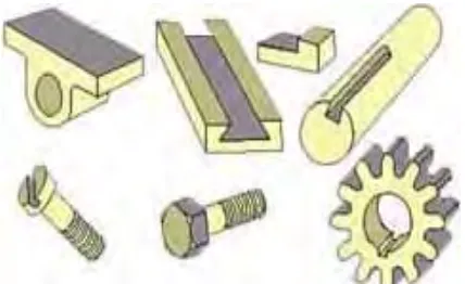
Figure 2.1: Component produced by a milling 6
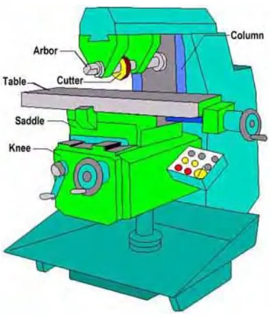
Figure 2.2: Horizontal Milling Machine 7
Figure 2.3: Vertical Milling Machine 8
Figure 2.4: Lathe machine with name of part 9
Figure 2.5: Bench drill 10
Figure 2.6: Cordless hand drill 11
Figure 2.7: Electric hand drill 11
Figure 2.8: Radial drill machine. 12
Figure 2.9: CNC Lathe machine 13
Figure 2.10: CNC milling machine 14
Figure 2.11: Conventional vertical milling machine 15
Figure 2.12: Up cut milling. 15
Figure 2.13: Down cut milling. 16
Figure 2.14: Holding method by using milling machine vise 17
Figure 2.15: Universal angle vise 17
Figure 2.16: Plain milling machine vise 18 Figure 2.17: Example of milling of a complex contour 20
Figure 3.1: Previous project design 21
Figure 3.2: System Development Life Cycle (SDLC) of the project 25 Figure 3.3: Problem that make the -4 degree error of clamp 26 Figure 3.4: the clamp mechanism will be refer. 27 Figure 3.5: New design for clamping vise 27 Figure 3.6: Side view of the previous base of the jig 28
Figure 3.7: New design for the base 28
xii
Figure 4.1 : Finish product. 32
Figure 4.3: New base part 33
Figure 4.2: Previous base part 33
Figure 4.4: Solid block of the base part 34 Figure 4.5: Block that have finish squaring 34
Figure 4.6: Dill three small hole 35
Figure 4.7: Parameter show in controller screen 35 Figure 4.8: Finishing surface at edge of T-shape 36 Figure 4.9: Surface finishing using face mill D63 36
Figure 4.10: Previous clamping jaw 37
Figure 4.11: New clamping jaw 37
Figure 4.12: Pocketing process in clamp jaw 38
Figure 4.13: Previous vise beam 38
Figure 4.14: New vise beam 38
Figure 4.15: Assemble of finish product 39
Figure 4.16: Drill diameter 11 40
Figure 4.17: Lock pin diameter 41
Figure 4.18: Place nut at rod 41
Figure 4.19: Tapping process problem 42
1
CHAPTER 1
INTRODUCTION
1.1 Background
Over the past century, manufacturing has made huge progress. New machine tool, high-performance cutting tools, and present day producing forms empower the present businesses to improve parts speedier and then at any other time. A standout amongst the most tedious and work broad procedures in the assembling of a mechanical part is the procedure of work holding or jig. Jigs are uncommon reason apparatuses which are utilized to encourage creation like machining, assembling and inspection operations.
2 The fixture designing and developed is well-thought-out as complex process that demands the understanding of dissimilar areas, such as geometry, tolerances, dimensions, procedures and manufacturing processes. While designing this work, a better number of literature and titles written on the subject by well-known authors are bring up. All outcomes and conclusions gained from the literature review and the interaction with fixture designers are used as guide to design the current research work.(Goutham.N and Ramesh Babu.K, 2007)
Milling process can be find in almost all industries, from a small scale industry which is conventional milling machine to big companies which is Computer Numerical Control (CNC) milling machine. It can be defined as the machining process of using rotary cutters to remove material from a work piece by feeding in a direction at an angle with the axis of the tool. Thus, the milling process requires a milling machine, work-piece, fixture and cutter. The work-piece is a pre-shaped material and it is located at the clamping vice.
1.2 Problem Statement
Most of the industry are use milling machine to produce die, aerospace, automotive and machinery. As a basic learning system for milling machining operation, most of the individual trained by convectional milling machine before they use the CNC milling machine.
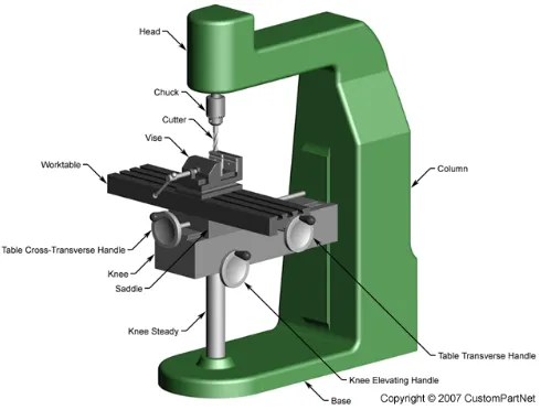
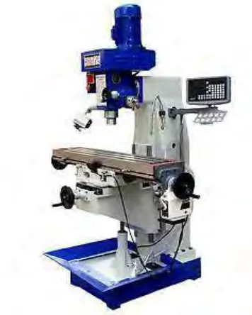
3 Figure 1.0: Manual vertical milling machine
Second problem from the previous jig is the thickness of the base jig. The base of the jig is too thick which is 50 mm refer Figure 1.1 below. When the thickness is high the weight of the jig will be increase and make the jig difficult to remove to other machine. The cost for making the jig also will be lower.
Figure 1.1: Side view of the previous base of the jig
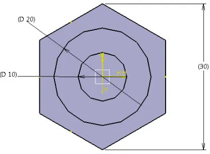
[image:16.595.243.414.393.557.2]4 Figure 1.2: Diameter of the previous rod
1.3 Objective
i. To modified clamp mechanism of the previous jig.
ii. To optimize the design of the fixable clamping jig for milling machine. iii. To analyze the result of fixable clamping jig in term of surface roughness.
1.4 Scope
The scope of this project will cover base on the objective, the scope are:
1) Change the clamp mechanism of the previous jig 2) Reducing of material usage from previous jig
5
CHAPTER 2
LITERATURE REVIEW
2.1 Introduction of Machining Process
The machining processes have important place in the traditional manufacturing industry. Cost effectiveness of all machining processes has been considered. This is for the most part influenced determination of right machining parameters like cutting speed, feed rate and depth of cut base on cutting tool and workpiece material. The choice of best machining parameters impact in extended tool life, well surface finish and higher material removal rate. During machining process, erosion between workpiece-cutting tools and cutting tool-chip crossing point to high temperature on cutting tool. The impact of this issue delivered heat that declines tool life, builds surface roughness and decreases the dimensional affectability of work material.(Çakīr et al., 2007)
The processes that have basic subject to controlled material removal are known as subtractive manufacturing. While in adjustment from processes of controlled material spreading out, and are known as addictive manufacturing. There are numerous sorts of machining operations. The example of the machining operations are turning, drilling and milling.
2.1.1 Conventional Machining
6 contact of tool and work-piece. There are numerous sorts of machining operations that fit for creating specific part geometry and surface composition which is milling, turning and drilling. Besides that, there are different operations that falling into incidental classifications incorporate shaping, sawing, boring and broaching.
2.1.1.1 Milling Machine
[image:19.595.225.439.497.628.2]A milling machine is a machine instrument that take away metal as the work is accommodate against a rotating multipoint cutter. The milling cutter rotates at rapid and it take out metal at a quick rate with the assistance of multiple cutting edges. At least one number of cutters can be mounted in the meantime on the arbor of milling machine. This is the reason that a milling machine finds fluctuated application in production work. Milling machine is utilized for machining flat surfaces, contoured surfaces, surfaces of revolution, external and internal threads, and helical surfaces of various cross-sections. Run of the mill segments created by a milling are given in Figure 3 .In numerous applications, due of its higher production rate and accuracy, milling machine has even changed shapers and slotters.(Singh, 2006)
7
Type of milling machine
[image:20.595.227.425.275.506.2]Most of the milling machines are made of “column and knee” structure and they are classified into two main types namely Horizontal Milling Machine refer Figure 4 and Vertical Milling Machine refer Figure 5. The name Horizontal or Vertical is given to the machine by orientation of its spindle axis. Horizontal machines can be more classified into Plain Horizontal and Universal Milling Machine. The main difference between the two is that the table of a Universal Milling Machine can be set at an angle for helical milling while the table of a Plain Horizontal Milling Machine is not.(Professional and Series, 2009)
8 Figure 2.3: Vertical Milling Machine
2.1.1.2 Turning Machine
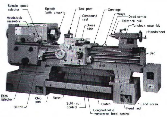
9 Figure 2.4: Lathe machine with name of part
Accuracy hard turning, characterized as single point cutting of part pieces with hardness of material in overabundance of 45 HRC under feed rate and fine depth of cut conditions, has turned into an alluring contrasting option to conventional grinding in numerous Industrial applications. It offers extremely considerable advantages, for example, ecological amicable and ability to fabricate complex workpiece geometry. In accuracy hard turning, the dimensional precision can achieve IT5 when wrapping up by accuracy hard turning with a CNC machine equipped with high-exactness movement control, high static and dynamic stiffness, and thermal stability systems. (Revel et al., 2016)
2.1.1.3 Drilling Machine
10 holes, numerous different operations can likewise be performed on the drilling machine, for example, counter- boring, countersinking, honing, reaming, lapping, sanding etc.(Singh, 2006)
2.1.1.4Type of Drilling
2.1.1.4.1 Bench Drill
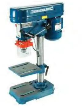
[image:23.595.257.391.358.535.2] Bench drill presses can be used to drill holes in small workpieces, Figure 7. These presses do not have as many abilities as the floor model.(Tinley Park and Illinois, 2000)
Figure 2.5: Bench drill
2.1.1.4.2 Hand Drill
Hand drill are used to drill small holes in relatively thin material. It are inexpensive and suitable to use. There are two type of hand drill which are electric hand drill and cordless hand drill. See Figure 8.
11 Figure 2.6: Cordless hand drill
Figure 2.7: Electric hand drill
2.1.1.4.3 Radial Drill
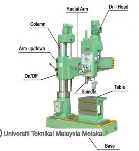
A radial drill press is make to manage very large drilling work. The drill head is mounted in a way that allows it to be moved back and forth on an arm that spread out from the huge machine column. The arm can be moved up and down and pivoted on the column, Figure 10.(Tinley Park and Illinois, 2000)
[image:24.595.220.446.585.830.2]