MEASUREMENT OF STRESS AND STRAIN OF AN AUTOMOTIVE COMPONENT SUBJECTED TO STATIC LOADING
NABIHA BINTI MOHMAD NUR
i
DECLARATION
“I hereby declare that I have read this project and my opinion this project is sufficient in terms of scope and quality for the award of the degree of Bachelor Mechanical
Engineering (Sturcture and Materials)”
Signature : ………
Name of Supervisor : Prof. Madya Abd Salam Mat Tahir
ii
MEASUREMENT OF STRESS AND STRAIN OF AN AUTOMOTIVE COMPONENT SUBJECTED TO STATIC LOADING
NABIHA BINTI MOHMAD NUR
This report is submitted as partial fulfilment of the requirement for the degree of Bachelor of Mechanical Engineering (Structure and Materials)
Faculty of Mechanical Engineering Universiti Teknikal Malaysia Melaka
iii
DECLARATION
“I hereby declare that the work in this report is my own except the summaries and quotations that has been duly acknowledged”
Signature : ………
Author : Nabiha Binti Mohmad Nur
iv
v
ACKNOWLEDGEMENT
In the name of Allah s.w.t, The Most Gracious, The Most Merciful. First of all, I would like to share my grateful and thank you Allah for giving me the
opportunity to study in this field. Without His permission there is no way I can complete this project successfully. It is such grateful that I can finally fulfil the requirements of Bachelor of Mechanical Engineering (Structure & Materials).
In this opportunity, I would like to thank Prof. Madya Abd Salam Md Tahir for giving me full guidance in this project. It is such a great experiences to work with him as he taught me with full of patient and always encouraged me to work hard in this project. Not just about the project, Prof Madya Abd Salam Md Tahir also always give his advices of how to be a better students and never ever tired to improve our skills in conversation in English.
Other than that, I would like to thank all the technicians in the Laboratory of Faculty of Mechanical Engineering for giving me full assistant on using all machines to fabricate my jig and conducting the experiment. Special thanks to En Faizul Bin Kamarul Zahari for assisting me in implementing the project from the beginning to the end.
vi
ABSTRACT
One of the important parts of the passenger vehicle is its braking system or specifically the brake pedal. This has been taken as the main research subject of this Final Year Projek (PSM). The measurement of stress and strain conditions of the brake pedal was determined by conducting a compression test to the brake pedal by controlling the travel distance of brake pedal. The study was done by designing and fabricating a special test fixture to hold the brake pedal while conducting the compression test by applying to static loading through the Instron universal testing machine. The compression load was applied to the brake pedal at three different areas and with three different travelling distance of 2 mm, 3mm and 4 mm
respectively. And the areas of applying force is at the centre, left and right side of the brake pedal and is known as F1, F2 and F3 locations respectively. The strain gauges are installed at the critical part of the brake pedal and connected to the strain meter for the determination of strain readings at the specified locations. The load of every position of applying force and travelling distance of braking system has been recorded together with the strain gauge readings. Based on this study, the main achievement of determining the value of maximum stresses or strains at the critical locations of the brake pedal has been done though some influential factors have significantly affected the final results. Other than that, the determination of
vii
ABSTRAK
Salah satu komponen yang penting di dalam kenderaan yang membawa penumpang adalah sistem brek atau lebih spesifik ialah pedal brek. Kajian ini telah diambil sebagai kajian subjek utama untuk Projek Sarjana Muda (PSM). Pengukuran tekanan dan tegangan di pedal brek dapat ditentukan dengan menjalankan uji kaji penekanan kepada pedal brek tersebut dengan menggunakan pedlbagai jarak sistem brek.Kajian ini telah dijalankan dengan mengfabrikasi ‘jig’ yang digunakan untuk memegang pedal brek tersebut semasa uji kaji dijalankan tertakluk kepada daya statik.Daya static dirujuk sebegai daya yang dikenakan dengan daya yang statik dengan struktur yang static tanpa mengubah posisi daya yang dikenakan. Uji kajii ini dijalankan dengan menggunakan tiga posisi keatas daya yang akan dikenakan di brek pad dan tiga jenis jarak sistem brek. Jarak sistem brek yang dikenakan ialah 2mm, 3mm dan 4 mm dan permukaan daya yang dikenakan di brek pad adalah di bahagian tengah, kiri dan kanan yang dikenali sebagai F1, F2 dan F3. . “Strain gauges” telah dipasang di tempat yang kritikal pedal brek dan telah disambungkan pada “strain meter” untuk mendapatkan bacaan nilai pemanjangan. Daya yang dikenakan pada setiap posisi daya dikenakan dan jarak sistem brek telah dicatat. Daripada
viii
CONTENT
CHAPTER TITLE PAGE
DECLARATION i
ACKNOWLEDGEMENT v
ABSTRACT vi
ABSTRAK vii
CONTENT vi
LIST OF TABLES vii
LIST OF FIGURES ix
ABREVIATIONS xi
CHAPTER 1 INTRODUCTION
1.1 Background 1
1.2 Problem Statement 3
1.3 Objectives 3
1.4 Scope of project 4
CHAPTER 2 LITERATURE REVIEW
2.1 Introduction 5
2.2 Brake pedal 6
2.3 Material of brake pedal 7 2.4Stress and strain behaviour of material 9
2.5 Bending stress 10
2.6 Strain 11
2.7 Static loading 12
ix
CHAPTER 3 METHODOLOGY
3.1Methodology introduction 14 3.2 Hardness test Rockwell 16 3.3 Designation of jig and brake pedal 17 3.4 Strain gauge installation 19
3.5 Test 20
CHAPTER 4 RESULTS AND DISCUSSION
4.1 Experimental results 22 4.1.1 Experimental data 22 4.1.2 Experimental Graphs 24 4.1.3 Experimental Calculations 29 4.2 Theoretical calculations 36 4.3 Comparison of Theoretical and
Experimental Results 39
CHAPTER 5 CONCLUSION AND RECOMMENDATION
5.1 Conclusion 43
5.2 Recommendation 44
REFERENCES 45
APPENDICES
APPENDIX A: FLOWCHART 48
APPENDIX B: GANTT CHART 50 APEENDIX C: HARDNESS TEST 52 APPENDIX D: EXPERIMENTAL DATA 53 APPENDIX E: MACHINE
FORFABRICATING 62
APPENDIX F: FABRICATION OF JIG 65 APPENDIX G: EXPERIMENT OF BRAKE
x
LIST OF TABLES
TABLES TITLE PAGE
2.3.1 Properties of carbon steel 8
2.3.2 Chemical composition of carbon steel 9 2.3.3 Mechanical of low carbon steel 9
3.5 Tabulated data 22
4.1 Experimental results 24
4.3.1 Experimental calculation for area 1 36 4.3.2 Experimental calculation for area 2 37 4.4.1 Theoretical calculation for area 1 39 4.4.2 Theoretical calculation area 2 40
4.5.1 Comparison results area 1 41
4.5.2 Comparison results area 2 43
B1 Gantt Chart PSM I 52
B2 Gantt Chart PSM II 53
xi
LISTOF FIGURES
FIGURES TITLE PAGE
1.1 Stress strain curve 2
1.2 Brake pedal 2
2.1 Braking system 6
2.2 Force applied on brake 7
2.3 Hooke’s Law graph 10
2.4 Dynamic loading 13
3.1 Procedure flowchart 16
3.2 Rockwell Hardness Machine 17
3.3.1 Jig design 18
3.3.2 3D view of brake pedal 18
3.3.3 Side view of brake pedal 19
3.4 Strain Gauge installation 20
3.5 Force applied on brake pad 21
4.1.1 Strain gauges area 1 23
4.1.2 Strain gauges area 2 23
4.2.1 20 mm Centre 25
4.2.2 30 mm Centre 26
4.2.3 40mm Centre 26
4.2.4 20 mm Left 27
4.2.5 30mm Left 27
4.2.6 40 mm Left 28
4.2.7 20 mm Right 29
4.2.8 30 mm Right 29
4.2.9 40 mm Right 30
4.3.1 Area 1 of brake pedal 31
xii
A1 PSM I flow chart 51
A2 PSM II flow chart 52
D1 Experimental data 20 mm centre 53 D2 Experimental data 30 mm centre 54 D3 Experimental data 40 mm centre 55
D4 Experimental data 20 mm left 56
D5 Experimental data 30 mm left 57
D6 Experimental data 40 mm left 58
D7 Experimental data 20 mm right 59 D8 Experimental data 30 mm right 60 D9 Experimental data 40 mm right 61
E1 Shearing machine 62
E2 Bend Saw machine 62
E3 Welding Machine 63
E4 Drilling machine 63
E5 Universal Tensile Machine INSTRON 64
E6 Digital Strain meter 64
E7 Load cell 64
F Jig 65
xiii
ABBREVIATIONS
UTM Universal Tensile Machine AISI American Iron and Steel Institute
1
CHAPTER 1
INTRODUCTION
1.1Background
2
With the availability of extremely small gauges, it is now possible to effectively use them for fracture studies. Static fracture studies have been conducted recently using strain gauges.
In structural engineering, understanding the behavior of steel under extreme loading conditions is essential for accurate prediction of material response when subjected to combination of severe load scenarios. The overall stress-strain relationship, as well as the mechanical properties of pre-damaged steel is investigated previously at various temperatures and under static loading [2](Mirmomeni et al., 2015). In addition, application of high static load induces irreparable plastic deformation to the material which cannot be neglected when assessing the resistance of the material at room and elevated temperatures.
In order to investigate the mechanical behavior of the pedal brake that will cause the failures, the mechanical test must be conducted with the brake pedal is subjected to various loading conditions.
.
For this study, it is crucial that the stress-strain curve of a material as shown in Figure 1.1 is known since it is one of the most important results that need to be determined and further investigated.The curve is normally used to measure a material’s mechanical properties such as the yield and ultimate strengths, Young’s modulus and ductility of the material. However, they are not without some subtlety, where in the case of ductile materials that can undergo substantial geometrical change during testing[4](Carlsson et al., 2006).
[image:16.595.237.436.430.573.2]3
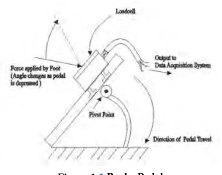
Figure 1.2 shows the brake pedal where the force is applied by foot of the driver with the angle varied. The maximum stress on the pedal brake is to be found under the various angle of applying load. There is a pivot point which can withstand the applied force or load.
1.2Problem Statement
[image:17.595.220.447.74.253.2]The mechanical problems of the brake pedal will cause a brake failure such as poor braking performance which will cause it harder or difficult to control and stop the vehicle. Other than that, squealing or grinding noises will occur during braking. Excessive drag during acceleration can also happen if there is a failure on the brake pedal. The brake pedal will typically crack on its critical zone which caused by the excessive loading on the brake pedal or caused by the overloaded pressure subjected to the brake pedal. The present study is conducted to investigate the stress-strain distribution on the brake pedal when subjected to static and dynamic loadings in such a way the location and magnitude of critical stress may be determined and identified experimentally.For the brake pedal, the magnitude of the applied load will depends on the travelling distance of braking system of the respective vehicle. Different size of vehicle will have different design and size of the brake pedal and also its travelling distance to apply load to stop or control the vehicle. For the purpose of this study, a locally manufactured
4
brake pedal for a passenger car has been chosen. It is a brake pedal ofPeroduaKancilwill be taken as the research object of the current study.
1.3Objectives
For the current study, a few objectives will be investigated to complete the scope of this project successfully. The main objective is to investigate the stress-strain behavior occurred on the brake pedal when applying the static and dynamic loadings. This is followed with the objective to investigate the maximum value of stress and applied force for a certain travelling distance of braking system and compare the experimental result with its theoretical value.
1.4 Scope of Project
The scopes of the current project are listed below;
1. To investigate the stress-strain behaviour or distribution on the brake pedal subjected to static and dynamic loadings.
2. To determine the maximum value of applied force for a certain distance of braking system and compare the experimental value with the
theoretical result.
3. Lastly, to investigate the effect of dynamic loading on the brake pedal when the force is applied at high rate or speed.
Furthermore, this project will be conducted with some limitations. The aerodynamic aspect of the car will not be included. In addition, the project will not be involved with test of other automotive part of the car.
5
CHAPTER 2
LITERATURE REVIEW
2.1 Introduction
This chapter will explain the stress strain measurement of an automotive part which is brake pedal of a car subjected to static and dynamic loadings. In order to measure the value of stress and strain, the experiment needs to be conducted by installing strain gauges on the brake pedal at a number of locations. The strain gauges will measure the value of strain that will be generated on the brake pedal while compressing the brake pedal with a certain load. The applications and review of strain gauges in measuring strains will be discussed in this chapter. The stress and strain analyses will also be covered in order to get a better understanding on this project.
2.2 Brake Pedal
6
Figure 2.1Braking system
helpful to users and will be much safe to use the vehicle with the latest design of braking system [7]. The cracking problems on a brake pedal was typically occurred due to the manufacturing defects of the brake pedal. The cracking also related to the higher stress-strain that exists on the critical section of the brake pedal [3].
The braking system in a car is normally made of mechanical, electronic and hydraulically activated components that used friction on the braking system as shown in Figure 2.1, either to stop the car or slower down the speed of the car. When the force is applied on the brake pedal as shown in Figure 2.2, it will produce a pressure that will moves a piston in the master cylinder. Next, the brake fluid from the master cylinder will force through the brake lines and flexible hoses to the calipers and wheel cylinders. As the driver push the brake pedal thus, the force will be applied. The applied force on the brake pedal is proportional on each of the pistons.
7
parameters which include the brake pedal travel, brake pedal force and the relationship for the car to stop and certain distances with times. Thus, by improving the parameters of the braking system will improve the effectiveness of the brake pedal.
2.3 Material of Brake Pedal
The actual material of brake pedal used in this study initially was not known except it appears as steel without details information from the manufacturer or supplier. Thus it is necessary to determine the actual type of steel being used to produce the Perodua brake pedal. This may be done through a number of methods such as conducting the tensile test, metallurgical study as well as the hardness test. The first two options will involve the destruction of the brake pedal, thus is it decided that conducting hardness test is the most viable method for the current study. By conducting the Rockwell hardness test, the material of the brake pedal was determined. The Rockwell hardness results gave the information of tensile strength based on the conversion table. From the literatures, it is found that the brake pedal was made from the carbon steel which met the standards of AISI 1018 of mild or low carbon steel. This material has good weldability which considered as the best steel that can be case-hardened. With the great balance of toughness, strength and ductility, brake pedalsare most suitable be made from carbon mild steel. To deform a brake pedal during its production, the carbon steel need to have specific manufacturing controls such as chemical composition, rolling and heating process. To ensure the brake pedal has strong structure, the fabrication process will include the welding, forging, drilling, machining, cold drawing and heat treating process [15]. The properties of the low carbon steel are shown in Table 2.3.1[16]
8
Table 2.3.1 properties of low carbon steel
Property Value
Density (kg/cm3) 7870
Poisson’s Ratio 0.29
Young’s Modulus (GPa) 205
Thermal Conductivity (W/moC) 51.9
[image:22.595.106.556.100.322.2] [image:22.595.111.529.423.679.2]Specific Heat (J/kg/oC) 486
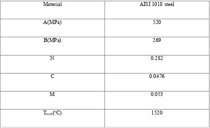
Table 2.3.2 shows the chemical composition of the low carbon steel, AISI 1018:
Table 2.3.2 Chemical composition of carbon steel Material AISI 1018 steel
A(MPa) 520
B(MPa) 269
N 0.282
C 0.0476
M 0.053
Tmelt(oC) 1520
9
Table 2.3.3 Mechanical propertiesof low carbon steel Mechanical Properties Metric
Hardness Rockwell 71
Tensile strength, Yield 370 MPa
Tensile strength, Ultimate 440 MPa
Modulus of Elasticity 205 GPa
2.4 Stress-Strain behaviour of a material
10
2.4.1 Bending Stress
For this project, the brake pedal was being compressed for a certain
distanceof braking system. The compression of the brake pedal will cause bending stresses alongthe brake pedal. Bending stress is a specific type of normal
stressgenerated longitudinally in the brake pedal material except on the neutral axis of the structure. The brake pedal will be subjected to compressive bending stress on the top side of itsneutral axis. While, the bottom side of the brake pedal experienced tensile bending stress. Generally, the bending stress vary linearly with distance from the neutral axis of the brake pedal. Equation (2.1) below shows that bending stress’s equation that vary with the distance from the neutral axis.
𝜎𝑏 =𝑀𝑐
𝐼
(2.1)
where,
𝜎𝑏= Bending stress
𝑀 = Bending moment
[image:24.595.190.482.68.267.2]𝑐= Vertical distance from neutral axis