UNIVERSITI TEKNIKAL MALAYSIA MELAKA
DEVELOPMENT OF HIGH TECH ELECTRICITY
SYSTEM IN AGRICULTURE FIELD
This report submitted in accordance with requirement of the Universiti Teknikal Malaysia Melaka (UTeM) for the Bachelor Degree of Engineering
Technology (Industrial Electronics) (Hons.)
by
NOOR AKMAL B. ABD MAJID
B071310077
900322-05-5121
BORANG PENGESAHAN STATUS LAPORAN PROJEK SARJANA MUDA
TAJUK: DEVELOPMENT OF HIGH TECH ELECTRICITY SYTEM IN AGRICULTURE FIELD
SESI PENGAJIAN: 2015/16 Semester 2
Saya NOOR AKMAL B. ABD MAJID
mengaku membenarkan Laporan PSM ini disimpan di Perpustakaan Universiti Teknikal Malaysia Melaka (UTeM) dengan syarat-syarat kegunaan seperti berikut:
1. Laporan PSM adalah hak milik Universiti Teknikal Malaysia Melaka dan penulis. 2. Perpustakaan Universiti Teknikal Malaysia Melaka dibenarkan membuat salinan
untuk tujuan pengajian sahaja dengan izin penulis.
3. Perpustakaan dibenarkan membuat salinan laporan PSM ini sebagai bahan pertukaran antara institusi pengajian tinggi.
4. **Sila tandakan ( )
SULIT
TERHAD
(Mengandungi maklumat yang berdarjah keselamatan atau kepentingan Malaysia sebagaimana yang
termaktub dalam AKTA RAHSIA RASMI 1972)
(Mengandungi maklumat TERHAD yang telah ditentukan oleh organisasi/badan di mana penyelidikan dijalankan)
TIDAK TERHAD
______________________
Alamat Tetap:
KAMPUNG GAMIN___________ 71550 SRI MENANTI_________ NEGERI SEMBILAN,_________ MALAYSIA___
Tarikh: _______________________
Disahkan oleh:
_______________________
Cop Rasmi:
Tarikh: _____________________
UNIVERSITI TEKNIKAL MALAYSIA MELAKA
BORANG PENGESAHAN STATUS LAPORAN PROJEK SARJANA MUDA
iii
DECLARATION
I hereby, declared this report entitled “Development of High Tech Electricity System in
Agriculture System” is the results of my own research except as cited in references.
Signature :
Name : NOOR AKMAL B. ABD MAJID
iv
APPROVAL
This report is submitted to the Faculty of Engineering Technology of UTeM as a partial fulfillment of the requirements for the degree of Bachelor of Engineering Technology (Industrial Electronics) (Hons.). The member of the supervisory is as follow:
v
ABSTRACT
vi
ABSTRAK
Kemajuan ekonomi pada masa kini seiring dengan kemajuan teknologi yang menjadikan kehidupan semakin ringkas. Pada hari ini kebanyakkan masyarakat bergantung kepada pelbagai jenis teknologi dalam mencari maklumat bagi melakukan sesuatu projek serta penyelidikan dan diantara contoh tersebut seperti kereta yang diaktifkan melaluli suara serta lain-lain lagi. Projek yang dijalankan ini memberi tumpuan kepada penanaman tumbuhan berkonsepkan rumah hijau dengan sumber asas yang tidak terbatas seperti air dan juga cahaya matahari. Sistem yang direka ini bertujuan membina satu sistem berkeupayaan tinggi dimana sumber yang dibekalkan akan dapat mengekalkan sifat semulajadi tumbuhan tersebut. Bahagian luar projek ini terdapatmya kotak kawalan utama dimana berfungsi mengawal pam air serta lampub dan juga mempunyai beberapa jenis sensor bagi mengukur tahap suhu tanah serta rumah hijau tersebut. Sensor yang digunakan bagi mengukur suhu tanah seterusnya akan menghantar isyarat kepada panel kawalan utama dimana terletaknya arduino dan seterusnya akan menghidupkan sama ada lampu atau pun motor pam serta mematikan proses tersebut apabila suhu yang sesuai Secara keseluruhannya, projek yang dijalankan bagi menghasilkan kerja membina rumah hijau, menjalakan ujikaji serta menyatakan bagaimana sistem didalam rumah hijau tersebut berfungsi.
vii
DEDICATIONS
viii
ACKNOWLEDGMENTS
In The Name Of Allah, the Most Beneficent and the Most Merciful. A deep sense of thankfulness to Allah SWT who has given me the full strength, ability and patience to complete this Bachelor Degree Project as it is today.
Firstly, I would like to take this opportunity to put into words my deepest gratitude and appreciation to my the project supervisor, Mr Hasrul Nisham Bin Rosly for his support, guidance, patience, encouragement and abundance of ideas during the completion of this project. Secondly, special thanks to both honourable panels, for their comments, invaluable suggestions and outstanding deliberations to improve the project during the project presentation.
ix
TABLE OF CONTENT
Abstrak i
Abstract ii
Dedication iii
Acknowledgement iv
Table of Content v
List of Figures vi
List of Table vii
CHAPTER 1
1.0 Introduction 1
1.1 Problem Statement 2
1.2 Objective 2
1.3 Scope 3
1.4 Project Outline 4
CHAPTER 2
2.0 Introduction 5
2.1 Smart Agriculture and Controlling System 5
2.2 Research from Previous Project 6
2.2.1 Design and Implementation of the Greenhouse Monitoring System 7 Based on GSM and RF Technologies
x
Based Intelligent Greenhouse.
2.2.3 Design of Intelligent Greenhouse Environment Monitoring System 9 Based on ZigBee and embedded technology.
2.2.4 Intelligent Agriculture Greenhouse Environment Monitoring System 9 Based on IOT
2.3 Hardware and Software Review 10
2.3.1 Arduino Controller 11
2.3.1.1 Introduction to Arduino 11
2.3.1.2 Arduino UNO 11
2.3.1.3 Advantages of Arduino UNO 12
2.3.2 Water Pump 13
2.3.2.1 1000 L/H Submersible Water Aquarium Pump 13
2.3.3 Relay 5v dc - 240v ac 14
2.3.4 Sensor 15
2.3.4.1 Humidity Sensor 15
2.3.4.2 Moisture Sensor 15
2.3.4.3 Temperature Sensor 16
2.4 Conclusion 17
CHAPTER 3
3.0 Introduction 18
3.1 Project planning and Development 18 - 19
3.2 Flow Chart 20
3.3 Identification Part 21
xi
3.5 Testing 22
3.6 Analysis 23
3.7 Summary 23
CHAPTER 4
4.0 Introduction 24
4.1 Result 24 - 28
4.2 Discussion 28 – 44
CHAPTER 5
5.0 Introduction 45
5.1 Conclusion for Chapter 1 45- 46
5.2 Conclusion for Chapter 2 46
5.3 Conclusion for Chapter 3 46 - 47
5.4 Conclusion for Chapter 4 47
5.5 Conclusion for Chapter 5 47 – 48
5.6 Commercialization Potential 48
REFERENCE 49 – 50
APPENDICES 51
xii
LIST OF FIGURES
Figure 1.1: The Flowchart of the System 3
Figure 2.1: The monitoring node hardware circuit diagram 7
Figure 2.2: The sink node hardware circuit diagram 7
Figure 2.3: The structure of the control system 8
Figure 2.4: The overall system block diagram 9
Figure 2.5: The structure of the system 10
Figure 2.6: The Architecture of Arduino Uno 12
Figure 2.7: 1000 L/H Submersible Water Aquarium Pump 14
Figure 2.8: Relay 5v dc - 240v ac 14
Figure 2.9: Humidity Sensor 15
Figure 2.10: Connection of Moisture with Arduino 16
Figure 3.1: Process flow of the project 19
Figure 3.2: Stage of completing the project 20
Figure 3.3: Block connection diagram of the project 22
Figure 4.1: The front view of the greenhouse model 25
Figure 4.2: The top view of the greenhouse model 25
xiii
Figure 4.4: The low condition of the greenhouse model 26
Figure 4.5: The wet range soil of the greenhouse model 27
Figure 4.6: The normal range soil of the greenhouse model 27
Figure 4.7: The dry range soil of the greenhouse model 28
Figure 4.8 Graph reading of moisture sensor for 8/9/2016 29 Figure 4.9 Graph reading of moisture sensor for 9/9/2016 30
Figure 4.10 Graph reading of moisture sensor for 10/9/2016 31
Figure 4.11 Graph reading of moisture sensor for 11/9/2016 31
Figure 4.12 Graph reading of moisture sensor for 12/9/2016 32
Figure 4.13 Graph reading of moisture sensor for 13/9/2016 33
Figure 4.14 Graph reading of moisture sensor for 14/9/2016 33
Figure 4.15 Graph reading of moisture sensor for 8/9/2016 35
Figure 4.16 Graph reading of moisture sensor for 9/9/2016 36
Figure 4.17 Graph reading of moisture sensor for 10/9/2016 37
Figure 4.18 Graph reading of moisture sensor for 11/9/2016 37
Figure 4.19 Graph reading of moisture sensor for 12/9/2016 38
Figure 4.20 Graph reading of moisture sensor for 13/9/2016 39
Figure 4.21 Graph reading of moisture sensor for 14/9/2016 39
Figure 4.22 Graph reading of average moisture versus time 42
Figure 4.23 Graph reading of average moisture value with temperature 43
xiv
LIST OF TABLE
Table 4.1: Reading of the moisture for chills value versus time ( % MC). 29
Table 4.2: Reading of the moisture for okra value versus time (% MC). 35
Table 4.3: Reading of the average value for okra (% MC). 41
Table 4.4: Reading of the average value for chills (% MC). 41
Table 4.5: Reading of the average moisture value versus time (% MC). 42
Table 4.6: Reading of moisture value for chills and okra with temperature 43
and humidity (% MC).
1
CHAPTER 1
INTRODUCTION
1.0 Introduction
2
suitable so that the plant can growth according to the desired level that of the plant itself. The desired level has been show on the control panel outside of the box outside.
1.1 Problem Statement
There are a lot of problem regarding the growing environment in the green house system. Therefore, the main idea to produce this project is based on the problem that were faced by the farmers and government that related in agriculture field, because environment changes in seasons bring about changes in the external and internal temperature of the greenhouse. These changes compel the grower to view things inside and outside the greenhouse differently. Although the idea is to attempts to keep the temperature inside the greenhouse uniforms. A change of the temperature because outside temperature increase out of comfort range or air move through greenhouse for cooling that bring unbalance temperature in different area will give different temperature due to the condition of the soil. The other problem view, farmers with fungus spores and small insects which is effect the growth of the plant and this give the plant with any outside or dangerous poison or disease.
1.2 Objective
Those objectives evaluated to assist and completing this project:
3
1.3 Scope
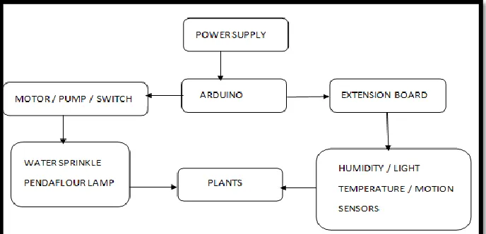
[image:17.612.172.516.431.597.2]The scope for this project to build HIGH-TECH systems in order to give continuous source to the plant so it will growth with the same condition according to its nature. At the outside of the box will be a control panel with the water pump that been used to pump the water for the water sprinkler and for controlling the light. In this project also there has been used of sensor to measure the level of temperature inside the greenhouse, humidity and also moisture of the soil. The sensor used in order to detect the level of moisture of the soil and after that will transmit the signal to the control panel for light to be turn on and off according to desired level of soil condition. Humidity also been use to detect if there any water in the air that can effected the growth the plant. All of these sensors has been control by Arduino that been connect to the circuit and give many advantage when using it such as open source, not so expensive for the cost, lower power consumption and lastly has many reference in order to create the coding for program. The Figure 1.1 shows diagram which represents the activity diagram of system. It shows the process of flow of activities.
4
1.4 Project Outline
a. Chapter 1 about describes the project, a problem statement, objective and also the scope of this project.
b. Chapter 2 been explained briefly about the literature review regarding and relate to this project
c. Chapter 3 process of construct and define the methodology that to be conduct that relate with practical and theory.
d. Chapter 4 about the result and analysis regarding the experiment that been doing.
e. Chapter 5 constructs the discussion of the result and analysis that been collected on the experiment process.
5
CHAPTER 2
LITERATURE REVIEW
2.0 Introduction
In this chapter, the literature review contains the information and also the idea for completing this project being discussed. There are many resource had been taken for this project such as books, journal, and also website. Beside, information about circuit, hardware and software which use in the project also include. This chapter also makes the study about the previous project in order to make some adjustment to improve or take some idea for this project. This kind of thing being very important and useful to complete the project that created.
2.1 Smart Agriculture and Controlling System
6
As the technology evolved over the last decade the world is becoming increasingly to face the problem of high-quality food shortage. One way to solve partially this problem is to use intelligent information technology for growing plants using intelligent greenhouse technology (Teslyuk, Denysyuk, Kernytskyy, & Teslyuk, 2015). In order to prevent these losses, various ways have been developing such as greenhouse system and also hydroponic ways. Therefore the use of wireless sensor and Arduino would be controlling the electrical used and minimum the maintenance. Thus this project to introduce the development system facilitates for farmers to optimize the usage electricity by using this smart system.
The plant that growth will be given the source like water and sun continuously according to it needed. Cultivation technique of greenhouse is the way to growth of plant that does not depend on the surrounding and keep the best of preserve environment by artificially controlling the environment(Kang et al., 2008). Thus the prototype to gives the owner or farmer minimize losses because of temperature balance and also living thing.
2.2 Research from Previous Project
7
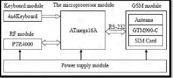
2.2.1 Design and Implementation of the Greenhouse Monitoring System
Based on GSM and RF Technologies
[image:21.612.209.512.364.463.2]In this previous project there has been another way in order to monitoring the system in greenhouse by using GSM and RF technologies which is radio frequencies that been closed communication. This communication also by using integrated the radio frequency. Radio frequency technology regional environment information monitoring network and combine with GSM remote communication. These system also consists of three part of hardware which is Hardware Design of Monitoring Nodes, Hardware Design of Sink Node and lastly remote communication that been referred to GSM network. The architecture of both systems has been shown in figure 2.1 and figure 2.2.
Figure 2.1: The monitoring node hardware circuit diagram.
[image:21.612.215.509.520.653.2]8
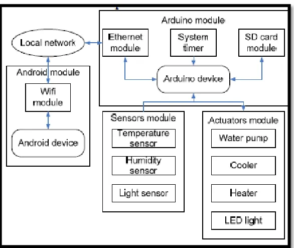
2.2.2 Automated Control System for Arduino and Android Based
Intelligent Greenhouse.
[image:22.612.216.509.320.567.2]In this project there used of Arduino and Android for controlling the system based on intelligent greenhouse. This system created to control of the intellectual greenhouse, collect statistics on system performance, system time setting. The data that has been collected from sensor, actuator and current activities that been doing during that time. It also communicates in two ways between the android and Arduino microcontroller that transmit the signal after receiving from the actuator and sensor used. The structure of control system has been shown in figure below.
9
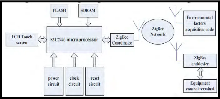
2.2.3 Design of Intelligent Greenhouse Environment Monitoring System
Based on ZigBee and embedded technology.
[image:23.612.185.537.282.441.2]In this project based on to design the greenhouse environment monitoring system also but using ZigBee and embedded technology. These system been created in order to meet requirement and sustained of crop growth in greenhouse precision agriculture. Wireless ZigBee network also used of multiple sensor such as humidity and temperature. It also set the warning in order to meet the actual condition. Figure below show the overall system block diagram at figure 2.4.
Figure 2.4: Theoverall system block diagram
2.2.4 Intelligent Agriculture Greenhouse Environment Monitoring System
Based on IOT
10
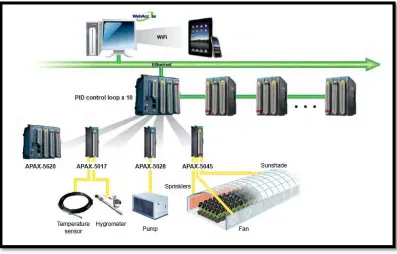
[image:24.612.150.547.133.387.2]pressure inside the greenhouse. Figure 2.5 show the structure of the system.
Figure 2.5: Thestructure of the system
2.3 Hardware and Software Review