1-1-2000
Development of a software program to train
individuals to use myoelectric prostheses
Scott David OpenshawIowa State University
Follow this and additional works at:https://lib.dr.iastate.edu/rtd
This Thesis is brought to you for free and open access by the Iowa State University Capstones, Theses and Dissertations at Iowa State University Digital Repository. It has been accepted for inclusion in Retrospective Theses and Dissertations by an authorized administrator of Iowa State University Digital Repository. For more information, please [email protected].
Recommended Citation
Openshaw, Scott David, "Development of a software program to train individuals to use myoelectric prostheses" (2000).Retrospective Theses and Dissertations. 17836.
by
Scott David Openshaw
A thesis submitted to the graduate faculty
in partial fulfillment of the requirements for the degree of MASTER OF SCIENCE
Major: Biomedical Engineering Major Professor: Patrick E. Patterson
Iowa State University Ames, Iowa
Graduate College Iowa State University
This is to certify that the Master's thesis of
Scott David Openshaw
has met the thesis requirements of Iowa State University
TABLE OF CONTENTS
ABSTRACT
INTRODUCTION
History of Prostheses History of Training Software Trainer Thesis Statement
METHODS AND MATERIALS Electronics
Myolab II Electrodes Pre amplifiers
Signal from the Myolab II output Inverting circuit
Handy Board and Motorola controller
Embedded software for the Handy Board Personal computer
Myotrain Software Program C++ software
Software design considerations Program display and setup
Visual display
Instructions and feedback Graphs and displays Signal processing
Interaction with the program Software arm model
Unlocked State 29
Locked State 31
Arm settings 35
Training Procedure 36
Training setup and procedures 37
Signals training 37
Controls training 38
Use training 41
Practice and testing 42
Experimental Setup 42
Control procedure 45
Day 1 45
Dey2 ~
Dey3 ~
Experimental procedure 49
Deyl ~
Day 2 50
Day 3 51
RESULTS 52
Learning Procedures Results 53
Practice Procedures Results 55
Testing Results 55
Test 1: Arm up, relax down to freeswing 56
Test 2: Arm up, force down with triceps 56
Test 3: Open hand, close hand 57
Test 4: Close hand, open hand 58
Computer Testing 64 Computer Test 1: Arm up, relax to freeswing 65 Computer Test 2: Arm up, force down with triceps 65
Computer Test 3: Open hand, close hand 66
Computer Test 4: Close hand, open hand 66
Computer Test 5: Lock and unlock 5 times 67
DISCUSSION 69
Learning Procedures Results 69
Practice Procedures Results 71
Testing Results 72
Test 1: Arm up, relax down to freeswing 73
Test 2: Arm up, force down with triceps 73
Test 3: Open hand, close hand 73
Test 4: Close hand, open hand 7 4
Test 5: Lock arm at any angle, unlock arm, relax to freeswing 74 Test 6: Lock and unlock 5 times in the full range of motion (ROM) 76 Test 7: Pick up cup, raise arm, drop arm and cup 77
Computer Testing 78
Computer Test 1: Arm up, relax to freeswing 79 Computer Test 2: Arm up, force down with triceps 80
Computer Test 3: Open hand, close hand 80
Computer Test 4: Close hand, open hand 80
Computer Test 5: Lock and unlock 5 times 81
Other Discussion 84
FUTURE CONSIDERATIONS 86
Software Enhancements 86
Software features 86
Training features 87
Additional Investigations
APPENDIX A: GAUGE PILOT STUDY
APPENDIX B: AGREEMENT AND SURVEY
APPENDIX C: POST-EXPERIMENTAL INTERVIEW REFERENCES
ACKNOWLEDGEMENT
89
91
93
95
96
ABSTRACT
In today's technological world, there is a push toward using computers to help with instruction and training. In 1990, a computer software program was developed and tested to train children how to control myoelectric motors. In this thesis the development of a software program that trains adults to control
myoelectric prostheses is discussed. An inverting circuit, a microprocessor, and other electronics help send electromyographic (EMG) signals from electrodes connected to the arm to a personal computer to be processed by the Myotrain software program.
Using Motion Control's training procedures for training individuals to use the Utah Arm, the software program models the Utah Arm 2 and teaches
individuals how to control an above-elbow myoelectric prosthesis. The software uses training instructions and feedback, and gives ample time for learning and practice.
Five experimental subjects were instructed on operating a myoelectric prosthesis using the software program. Five control subjects were instructed on the use of the Utah Arm at-elbow as is currently done for training new
prosthetic users. After two days of training, all ten subjects returned a third day and were tested on the Utah Arm and on the software to determine success levels by each subject.
All subjects showed improvement of skill over time. Users trained only on the software were able to control a myoelectric prosthesis when tested on the third day. The software was successful in teaching adults to move the Utah Arm. There was no significant difference between the abilities of the control and experimental groups in controlling the Utah Arm.
INTRODUCTION
History of Prostheses
For centuries, prosthetic devices for upper-limb amputees or individuals with upper-limb defects have been needed. During the Medieval Period,
surgeons tried to transplant limbs so that amputees could have an "artificial" limb [10]. In 16th century Rome, individuals were fitted with an artificial bronze arm [10]. Since that time, many technological advances have occurred which help individuals without limbs to live a more normal lifestyle.
Lighter materials such as composite plastics and graphite composites have replaced the heavier metals that were used for earlier prostheses. These lighter materials enable prosthetic users to have more mobility and a more life-like artificial arm. In the 1950s body powered prostheses were common for prosthetic users [19] [20]. These limbs typically consist of a cable that is attached to a shoulder harness (Fig. 1). When the user moves his or her shoulder forward, the terminal device (TD) on the end of the arm opens. This TD is usually a hook used for
grasping purposes. These devices are still common and it is estimated that 90% of upper-limb amputees wear this type of conventional device [11].
Since the 1950s,
researchers have tried to find ways to interface biological muscle and nerve signals to control artificial arms. Wiener in 1948 suggested, in his book
Front View Back View
Cybernetics, that biological signals could be used to control devices. Rieter was the first to develop a hand that was controlled by electromyographic (EMG) signals [4] [22]. Since Rieter's development, many other advances have been made. Jacobsen and others named a few of the advances that occurred: IBM arm, Russian EMG controlled hand, Viennatone hand, Boston elbow from Massachusetts Institute of Technology, Veterans Administration elbow, Boston elbow from Liberty Mutual Insurance Company Research Center, Otto Bock hand, Fidelity hand, Italian arm, New York University elbow, Variety Village elbow, Utah arm, Japanese research, Otto Bock pincer [4].
Each of these advances and developments created devices that were controlled by myoelectric signals. The EMG signals controlled motors in the elbow joint of the prosthesis, or in the hand or terminal device of the arm. Since the initial research developments of the 1950s, more commercial myoelectric devices have been placed on the market for amputees to use. Three examples include: the Utah Arm (Fig. 2), the Boston Elbow, and the ProControl Arm (Fig.
Figure 2. The Utah Arm 2 is one of the commercial
[image:10.561.137.427.436.650.2]3). Motion Control in Salt Lake City, Utah manufactures the Utah Arm and the ProControl Arm, while Liberty Mutual Insurance Company manufactures the Boston Elbow. Each of these prosthetic limbs targets upper-limb amputees. These amputees are either above-elbow or below-elbow amputees, depending on the location of the arm amputation with respect to the elbow. (Reference to amputee in this thesis will address individuals who have lost use of their arm due to amputation, birth defect, or other causes.)
Figure 3. This below-elbow myoelectric prosthesis is known as the ProControl 2 Arm. It has both a hand and wrist motor with myoelectric control. Used by permission from Motion Control.
The basic function of the externally powered myoelectric prosthesis is to control motors in the prosthesis with the contraction of remnant muscles. The commercial myoelectric arms mentioned use this approach to control the movements of the individual's prosthesis. One method of control for a
above-elbow or below-elbow, will provide control for at least two motors.
Typically, an above-elbow prosthesis (Fig. 2) controls an elbow motor to bend the elbow up and down and a hand motor to open and close the hand. A below-elbow prosthesis (Fig. 3) will usually have a hand motor and a wrist motor. The latter will cause the wrist to rotate. To rotate the wrist on an above-elbow prosthesis that is not equipped with a wrist motor, the user must manually turn the wrist to the desired position before opening or closing the hand.
There are about 10,000 new upper extremity amputees each year [20], but only about 5,000 receiving some type of prosthetic device to replace their arm [12]. These 5,000 individuals represent about 5% of the work performed by prosthetists in the United States [13]. The market for upper-limb prostheses is not one of high-volume demand; therefore, many investors and researchers do not spend as much time and money in this industry as in lower-limb industries [13] [4]. As mentioned before, 90% of prosthesis users use body-powered
prostheses instead of myoelectric prostheses [11] [21].
History of Training
Even with the small number of myoelectric users each year and few myoelectric arms on the market, there exists a need to train users to control a myoelectric prosthesis. A prosthetist and therapist are involved in training an individual to control the prosthesis. The training procedure and amount of time taken to train individuals depend on many variables such as user motivation, training protocol, and ease oflearning by the user [14]. The therapist usually does the majority of the training with the individuals and usually sits at-elbow with him or her to provide immediate feedback and assistance.
Following this procedure, the individual is trained on the basic control features
of a prosthesis, such as flexing and extending the elbow. Use training includes
instructing the user on how to control the prosthesis to pick up objects, place
objects, or to pre-position the arm for different functions. The final part of
training is teaching the user to utilize the arm in scenarios that are part of his or
her daily routine. Some examples may include hammering a nail, cracking an
egg, or saddling a horse.
There is no standard training protocol that is documented for all
therapists to use. The only standard for training that exists is the accreditation
of the different orthotic and prosthetic (O&P) educational programs by The
National Commission on Orthotic and Prosthetic Education (NCOPE). NCOPE
certifies the different educational programs to make sure that they are teaching
future prosthetists and orthotists the necessary information to be thorough and
efficient in their profession.
Over the years of myoelectric prosthesis use, there have been some
advances in training that take advantage of growing computer technologies. A
microcomputer trainer was developed by Lovely to help trainers combine the
functions of many prosthetic devices into one computerized trainer. [17]. In
1990, D.F. Lovely and others published results on a computer-aided training
system for helping young children learn to control myoelectric devices. Their
computer program included games that allowed children to control a computer
screen cursor with both a joystick and myoelectric signals. Other innovative
trainers include a visual feedback trainer created by scientists in Australia
which gives feedback via light emitting diodes (LEDs) depending on the
sequences of contractions and operations of the arm [15]. Motion Control has
created a software trainer that will allow a user to see the contractions and
signals coming directly from their ProControl arm as they are using it. The
software also allows a user to set certain controls through a computer rather
The main aim for those trying to develop more advanced training systems
is to help the users have a more natural, efficient, and effective way to learn to
use a myoelectric prosthesis [13].
Software Trainer
As automation and computer use increase, there is a push in the
myoelectric industry to create devices that will help train individuals to control
myoelectric prostheses. Lovely's software program that taught children to use
myoelectric signals to control a cursor on a computer monitor [16] was a step
toward computer-based training. Since their work, there has been little progress
in the way of computer-based training. Motion Control's new ProControl 2
system allows users to see signals produced from muscle contractions and arm
movements, but it does not take them through a training procedure to learn to
use and control the prosthetic device [7].
A computer-based myotrainer would be useful to prosthetic users because
they would be able to learn to use a myoelectric prosthesis before they are fitted
for one. Learning how to read and understand EMG signals and their function
in control sequences can help the user to decide if a myoelectric prosthesis would
be appropriate for his or her needs. With a computer program, potential
myoelectric users could be trained while waiting for the arm to be fitted, saving
time by decreasing the amount of time spent testing and learning at-elbow with
a therapist. A trainer of this type will not replace the therapist, but serve as a
supplement to reinforce the principles used in training for myoelectric use.
Ultimately, the software trainer may help the user become more independent,
reduce costs associated with training and fitting, and allow a user to obtain
feedback when a prosthetist or therapist is not present during the personalized
Thesis Statement
A personal computer with an appropriate software trainer and arm model
can teach adults how to control a myoelectric prosthesis. This thesis describes
the development of such a trainer and shows its effectiveness by comparing the
results of subjects trained with the software trainer and subjects trained by
METHODS AND MATERIALS
Four parts were involved in developing the software trainer: electronics,
software programming, training procedure protocols, and experimental setup.
The following part of this thesis will explain how these four areas were
developed and prepared for experimental use.
Electronics
The electronic setup of the experiment consisted of interfacing the
myoelectric potentials in the user's muscles with the serial port of the PC where
the software trainer was loaded (Fig. 4). The hardware between the muscles and
the PC included:
User's Computer
Handy Board
Myolab II
Figure 4. Five components of the experimental setup. The
• Myolab II myotester with electrodes and preamplifiers
• Inverting circuit
• Handy Board for analog to digital (ND) conversion
This equipment read the EMGs when the user contracted his or her arm muscles
and converted them into digital signals that could be read by the PC software
trainer.
Myolab II
A Myolab II (Motion
Control, Salt Lake City, UT)
(Fig. 5) was used to read the
analog signals from the
electrodes. It is a myotester
that is used by some therapists
to help train individuals to find
optimal EMG sites for
electrode placement to control
a myoelectric arm. The Myolab
II consists of electrodes (input),
analog display dials (output),
muscle frequency sound
outputs, and a signal output line.
Electrodes
Figure 5. The Myolab II processed the
EMG signal from the electrodes and sent the signal to the inverting circuit so that it could be read by the Handy Board.
Included with the Myolab II myotester was a pair of horizontal bar
electrodes, each containing three stainless-steel electrodes for positive ( + ),
negative(-) and ground leads (Fig. 6). Each bar can be placed over an opposing
muscle group such as the flexor and extensor muscles of the forearm and used to
Preamplifiers
Ground ····
-/+
Figure 6. Electrodes and preamplifiers used to collect EMG signals from muscle contractions. The
preamplifiers help to process the signal to be read by the Myolab II.
that occur in the muscles during contraction. The middle electrode is a ground
or reference electrode for the other two [8].
Electrodes are ideally placed on antagonist muscles (i.e., biceps and
triceps) in order to control the prosthesis [19]. One muscle's signal will cause the
prosthesis joint to flex. The other
muscle's EMG will cause the joint to
extend. The three electrodes on the
horizontal bar are similar to
electrode placement inside the
socket of most prosthetic devices
(Fig. 7). The electrodes used in the
experiment were connected to
preamplifiers to help amplify the
weak EMG signals (Fig. 6).
Two horizontal bars
of electrodes were used on
the subjects, one on each
muscle group (Fig. 8).
The electrodes were
placed over the muscles,
and contractions were
induced to produce EMG
signals. These signals
were evaluated until the
best difference between
biceps and triceps
contractions was found.
This difference was
necessary to be able to
Front 'View Back View
0
Biceps or Flexors (Flex elbow, open hand)411!>
Triceps or Extensors (Extend elbow, close hand)Figure 8. Location for electrode placement for above-elbow and below-elbow amputees.
Subjects in this study used above-elbow muscle sites (biceps and triceps).
control the Utah Arm efficiently. When strong signals were located with the
electrodes, these locations were marked as optimal sites for EMG
measurements.
Preamplifiers
Normally the signal frequency for EMG signals ranges from 25 Hz to
several kilohertz (kHz) and the voltage ranges from 100 µV to 90 mV [1]. These
voltages are normally too small to be detected and seen clearly; therefore, most
EMG signals are amplified. The Myolab II's preamplifiers, mounted inside the
horizontal bar, allowed the signal to be amplified at a gain of about 375 at 300
Hz [25]. This gain produces a signal in the range of 0.1-1.0 Vin the Myolab.
The basic configuration of the electrodes allows the user to hold the
electrode bar to his or her arm while muscles are contracted. Voltage potentials
the preamplifiers. From the preamplifiers, the signal is differenced with the
opposing muscle's signal and the differentiated signal is amplified. This final
signal is seen on the Myolab II's analog dial display. It can also be detected as a
voltage on the output line of the Myolab (Fig. 9).
El ectrodetPream p Jack (Input)
External f\ilonitor (Output)
1-Ch A ar111lified E MG. signa I 2- Ch B anl)lified E MG signa I 3- HOT USED
4- Gnn•ul
5- Ch A processed signal 6- Ch B processed signal 7-Ch A amio output 8-Ch B aucio output
1 2 3 4 5 6 7 8
Figure 9. Explanation of the Myolab II's ports found in the battery component of the myotester. Ports 4, 5, 6 were used for the output signal to the inverting circuit.
Signal from the Myolab II output
The output port used on the Myolab II is normally used by therapists to
control one of Motion Control's myoelectric arms during training and
troubleshooting exercises with a client. The port allows a user to read the
signals that are coming into the Myolab II from the electrodes. Two of the
signals that come out of the Myolab II output port are processed signals for each
channel (A and B). The processed signals are inverted with a range from Oto -2
V when the Myolab II gain dials are set at 10. The needle on the front of the
Myolab measures the signal from the electrodes and preamplifiers with a range
The Myolab II also has gain controls to fine-tune the strength of signal in each muscle group. The gains range from 0-12, with the "normal" setting being
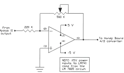
10 [25]. This gain setting of 10 produces a reading of -1 V from the output port during a contraction that reached 100% on the dials of the analog output display on the front of the Myolab II. When the gain is set at 10 and a contraction is showing 100 on the display, this would correspond to 100 µV coming from the electrodes and preamplifiers (a factor of 1/1000 of the processed signal). An additional electrical circuit (Fig. 10) was created to invert the Myolab II's signal and amplify it for reading the signal on the AID converter of the Motorola
68HC11 microcontroller (Fig. 11).
Frol"I
l1yolo.b [ [ -au tput.
220 K.
<:»
+
500 K
5 V
.__(6_) _ _ _ _ .... To Han~y Baarci
-'5 V
NOTE= :±5V power inp~ts to LM7 41 col"I e- fr"Of'I the LM 7805 circ ui't
[image:21.559.66.491.345.595.2]A/ 0 c onve-r t'i:'r
LCD Screen Inverting circuit
The analog signal from the
Myolab II was ultimately read by
an AID converter on the Handy
Ground Board, a microcontroller based on
AID Converter Chmnel 1
AID Converter Channel 0
Figure 11. Handy Board with
Motorola's 68HC11 microcontroller used for analog to digital conversion.
the Motorola 68HC11 chip and
created by Fred Martin [5]. The
negative voltage from the Myolab
had to be inverted and amplified by
a separate circuit (Fig. 10) to
achieve optimal reading by the AID
converter. The circuit was a
standard amplification circuit using an LM741 operational amplifier (op amp), a
220 KQ resistor, and a 500 KQ potentiometer. The op amp was powered by± 5
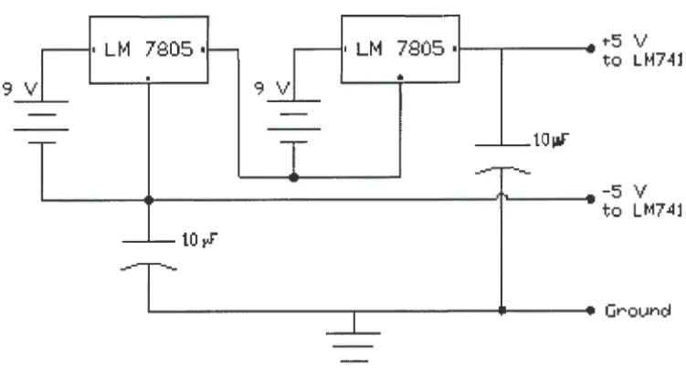
V, supplied by the combination of two 9 V batteries and two LM 7805 voltage
regulators (Fig. 12). The voltage to the op amp was kept at 5 V because the
highest recommended voltage entering the AID converter of the 68HC11
microcontroller was 6 V [27].
Using the inverting circuit also reduced the risk of electrical shock to the
individual because it was another path through which an unexpected and
unlikely voltage spike from the PC's alternating current (AC) would have to
travel before it reached the electrodes on the individual. Furthermore, by using
9 V batteries, the use of an AC power adapter to power the circuit was avoided.
An AC power adapter could potentially introduce unwanted voltages and
7805 I 7805 •i - - ~ - - -. . ""5 V
to LM74l
•
9 V
___._taw
.__ _ _ _ _ _ _ _ _ _ _ _ _ _ _ _ _ _ _ _ ~, .... _ _ _ -5 V
to LM74l
10~
[image:23.563.85.461.90.291.2], . . _ - - - . . . . - - - Groun~
Figure 12. Voltage regulator circuit used to power the inverting
circuit and prevent voltages greater than 5 V reaching the Handy Board.
Handy Board and Motorola controller
The AID converter on the Handy Board sent the digital values of the myoelectric signals over the serial port to the PC. The Handy Board was programmed for AID conversion and serial communication using Interactive C (IC), a computer language similar to C.
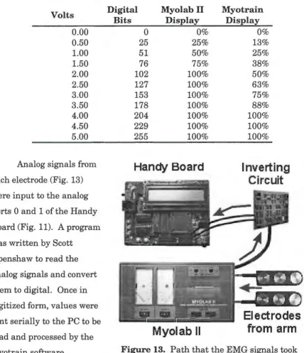
The Handy Board's AID converter has a range from Oto 5 V (0 V = 0 bits, 5 V = 255 bits) [5]. Since the signal output from the Myolab II ranges from Oto -2 V, the inverting circuit used in the experiment amplified the signal with a gain of 2. This amplification gave a signal of O to 4 V from the inverting circuit to the
AID converter. This range of analog voltage corresponded to digital values in the range of Oto 20410' or a resolution of 19.6 m V per bit (Table 1) [26]. The
Table 1. Conversion table for determining voltage and relative strengths of contraction. Resolution of the analog to digital converter is 1 bit = 19.6 m V. The Myolab II displayed a relative range from Oto 2 V and the Myotrain software displayed a range from 0 to 4 V.
Volts
0.00 0.50 1.00 1.50 2.00 2.50 3.00 3.50 4.00 4.50 5.00
Analog signals from each electrode (Fig. 13) were input to the analog ports 0 and 1 of the Handy Board (Fig. 11). A program was written by Scott
Openshaw to read the analog signals and convert them to digital. Once in digitized form, values were sent serially to the PC to be read and processed by the Myotrain software.
Digital Myolab II
Bits Display
0 0%
25 25%
51 50%
76 75%
102 100%
127 100%
153 100%
178 100%
204 100%
229 100%
255 100%
[image:24.561.59.488.172.669.2]Handy Board
Myolab II
Myotrain Display 0% 13% 25% 38% 50% 63% 75% 88% 100% 100% 100%Inverting
Circuit
Electrodes
from arm
Figure 13. Path that the EMG signals took
Embedded software for the Handy Board
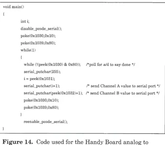
Figure 14 shows part of the program that read the analog signal,
converted it to a digital signal, and then sent it to the serial port. To be able to communicate with the PC's serial port, extra code had to be added to the IC program written by Scott Openshaw. This additional code was created by Randy Sargent and published on the MIT web site [5].
lnitally the PC had trouble reading the signals during contractions when either port on the Handy Board read a zero voltage signal. When the Myotrain software tried to read the zero value, it prevented the dial meter in the training
window from moving. To solve this problem, a value of 1 bit was added to the serial_putchar function for both channels (Fig. 14). Because of this, each value read by the software was 1 bit greater than the true voltage reading.
void main()
inti;
disable_pcode_serial();
poke(0x1030,0x10); poke(0x1039,0x80); while(l)
while (!(peek(0x1030) & 0x80)); /*poll for aid to say done */ serial_putchar(255);
i = peek(0x1031);
serial_putchar(i+l); /* send Channel A value to serial port*/ serial_putchar(peek(0x1032)+1); /* send Channel B value to serial port*/ poke(0x1030,0x10);
poke(Oxl039,0x80);
[image:25.561.98.436.389.686.2]reenable_pcode_serial();
Figure 14. Code used for the Handy Board analog to
Personal computer
A Pentium II-266 MHz IBM-compatible computer was used to execute the software training program and to receive serial input from the Handy Board.
The signals received over the serial port were used to control the logic for arm model and training. The PC also served as a graphical interface allowing the user to see visual information on a monitor and to run the necessary training
procedures to learn to control a myoelectric prosthesis.
Myotrain Software Program
The Myotrain software program was developed and written by Jeremiah
Patterson and Scott Openshaw. This software was the primary trainer of individuals using the PC training system to learn to use myoelectric prostheses. Programmed with Microsoft's Visual C++, Myotrain gave the user a graphical user interface (GUI) with menus, instructions, training procedures, and
feedback. The Myotrain software had a simple and basic model of the Utah Arm 2 built into the code to allow for effective feedback to the user.
C++ software
Microsoft's Visual C++ was used because of its versatility and object-oriented programming capabilities [24]. With Visual C++, it was possible to
program for easier control of myoelectric arm logic, graphical display of muscle contractions, versatility, and flexibility. C++ was also chosen because it is a common and widespread programming language used in today's software market [23]. This would allow others to add to what was accomplished in this experiment.
Software design considerations
In designing this software program for training individuals, different
simulation software program cannot be setup without planning the educational
content and strategies [2]. Although the Utah Arm training procedure has been
used over the years in myoelectric training, interfacing these procedures with a
1 software simulation needed to be done effectively so that there was educational
value in the software training program.
Walker and Hess [2] compiled information that was presented at different
symposia to show what was needed in Computer Aided Instruction (CAI) to
make it more effective. Many of the ideas and procedures that were included in
our software program were contained in their book Instructional Software. The
most common types of CAI are: drill and practice, simulations, and tutorial [2].
The Myotrain program gives the myoelectric trairtees an initial tutorial showing
them how to use and control the arm. After the tutorial, they are given the
chance to practice all the control procedures taught in the tutorial. The final
part of the software program tests their proficiency in controlling the arm.
The Myotrain software program design was guided by the following
considerations: visual display, instructions and feedback, and interaction. Each
of these parts helped create a program that followed pedagogical principles.
Program display and setup
The Myotrain software was
created with menus and various
informational windows for ease in
navigation through the program. The
menus allowed users to choose where
to begin when they started the
program (Fig. 15). The three main
areas of the training portion of the
program included: Training (included
Figure 15. Main Menu options
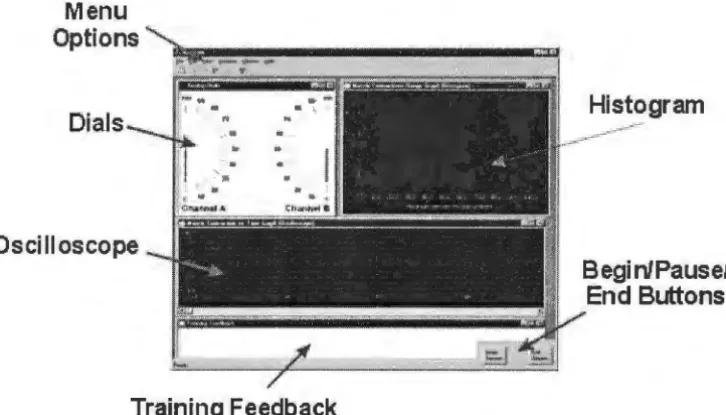
Testing EMG sites and Learn Procedures), Practicing, and Testing. Each of these will be discussed later because they are part of the training mechanism of the program, providing both written and graphical feedback to the user.
Various windows of dials and gauges on the screen provided the user with feedback during operation of the Myotrain program (Fig. 16). This information was provided to help in training and to reinforce successful operations, or to correct unsuccessful attempts. The feedback windows and text are similar to the information that a prosthetist or therapist would provide to the user during at-elbow training [9].
Menu Options
Dials
Oscilloscope
Training Feedback
[image:28.564.92.455.302.509.2]Begi nlPausel End Buttons
Figure 16. The Myotrain program display used during
training and testing. Each window is used in different ways to provide effective and essential feedback to the user.
Visual display
Colors were selected for the visual display to create a contrast that helped the user focus on the important parts of the program and clearly see the
allowed users to know where objects would
be and not have to readjust each time that
they went to another part of the program.
Each screen or graph was labeled with a
title, and the screen displays were simple
for ease in use by the trainees [2].
In a menu-driven program, it is
important to make sure that the menu
options are self-explanatory, have
consistent wording, and allow for
submenus or shortcuts (Fig. 17) to be used
Signals Training Options 13
Figure 17. The Training Menu was primarily used for testing EMG sites and learning procedures of the arm, but shortcuts were added to allow users to practice or be tested from this menu.
to accommodate differently skilled users [2]. The simple menu display in the
software allowed users to easily select the area where they wanted to begin, or
select a submenu to explore other options in the program. The menus also
allowed for the user to return to the main menu and select other options, if
needed.
Instructions and feedback
There were two types of feedback provided in the Myotrain program:
graphical and written. Since Myotrain is a training program, instructions and
feedback are imperative and must be direct, clearly, and meaningful. The
instructions presented in the software showed the user how to control the
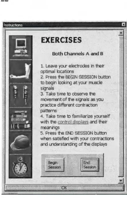
myoelectric signals and what exercises to perform during certain tasks (Fig. 18).
Walker and Hess explain that it is necessary for CAI to give learning outcomes,
state clear objectives, and give teaching steps [2]. Before each instructional or
practice procedure, the instruction window (Fig. 18) displayed learning outcome
information, procedures that would be practiced, and steps needed to accomplish
the user the ability to control the
learning by working alone to
accomplish the given instructions.
EXERCISES
Both Channels A· and B
1. Leave your, electrodes in their gptimal lqcatlons .
2. Press the BEGIN SESSION button
to begin looking at your muscle sigmils
3'. Take time. to observe the movement cifthe signals as you practice different contraction
pa~rns
4. Take time to familiarize yourself With the~ and their meanings
, 5. Press the END SESSION button when satisfied with your contractions and understanding of the displays These instructions were
written in HyperText Mark-up
Language (HTML), a standard used
in Internet web design. The ease of
navigation and linking in HTML
coding allowed the instructions to
be hyperlinked and provided easy
access to any information that users
wanted at any time. Users could
access the Instruction window at
any time by pressing the
Instructions button at the bottom of
the main screen (Fig 19).
The other type of written
feedback that was given to the users
[image:30.563.266.488.55.400.2]were the instructions in the
Figure 18. Instructions window used to teach the user how to operate a myoelectric prosthesis. The window also gave specific exercises to perform when applicable.
Training Feedback window (Fig. 20)
at the bottom of the screen. The written
feedback showed the user what was
happening with the arm and provided
information on the user's performance.
The feedback in the program was specific
to the training procedure and told the
user what he or she was doing well or
needed to improve [2].
Figure 19. The button bar at the bottom right corner of the main screen allowed users to choose options, such as
Instructions and Arm Settings.
he elbow is locked Thresholds he hand can now be controlled: Practice Un/lock Elbow: 25
Hand: 20 Freeswing: 15 Co High: 45 Co Low: 30
Figure 20. The Training Feedback window gave users information on
what was occurring with the arm model as they contracted their muscles. It also displayed the current arm settings for arm control. This sample feedback screen was taken while the user was practicing the locking and unlocking of the elbow. The user had just locked the elbow and was being instructed that the hand could now be controlled.
Graphs and displays
The other type of feedback given to the users was graphical feedback. The
analog dials, histogram chart, and oscilloscope graph helped to give visual
feedback to the users. These types of
visual feedback are consistent with the
feedback principles of reinforcement
and helpfulness [2].
The dials (Fig. 21) showed what
was happening with contractions.
Similar to the dials on the Myolab II
(Fig. 5), the analog dials showed the
strength of the amplified muscle
contraction as a relative percentage
from Oto 100%. This display helped
show the user when he or she
contracted a certain muscle (either the
..__;,_· 40
"
.
;\ ,·· 30I
11 ,\ \ ' 200 10
Channel A
60
90 100
so . , , \'\\I 70
,
,
.... \Figure 21. Analog dials showed
flexor or the extensor) and displayed a visual measurement of the amount of force or strength in the contraction. This meter also helped to show the user if he or she was successfully executing other arm coordination and controls, such as locking and co-contraction (unlocking).
Another display on the screen was the histogram graph (Fig. 22) that showed the user how many contractions had been performed within a certain strength range. Each time a user contracted a muscle, the histogram displayed a one-unit increase in the range of contraction. For example, the user in Figure 19 contracted the biceps brachii 3 times and triceps brachii 4 times in the 30% range. This graph informed the user of how frequently he or she was contracting in the correct range and where the majority of contractions was occurring.
Feedback could be given to the user to modify strengths of contractions, if necessary.
The final graphical display was the oscilloscope display which gave a graph of strength-of-contraction vs. time (Fig. 23). The oscilloscope showed what was happening at the present time and also displayed past events. Users and
#
0 f
A
t t
e
m
p
t s
4
3
2
1
I
I
0 10.0 20.0 30.0 40.0 50.0 60.0 70.0 80.0 90.0 100.0
Maximum percent for one attempt
Figure 23. Oscilloscope graph showing how the signals on Channels
A and B changed over time. This graph was useful for analysis both during and after training.
therapists could use this display to see how strength of contraction changed over time. Decreases in contraction strength, co-contraction and locking procedures, and general arm and hand movements can be identified with this display. The total displaying time of this graph was 400 seconds (6 minutes and 40 seconds).
Signal processing
The signals from the Handy Board were converted from analog to digital and the digital values that went into the PC serial port ranged from 1 to 225 bits. The software took the Root Mean Square (RMS) of as many values that it could obtain in 10 ms. This averaging allowed the signal to smooth out some of the noise from muscle contractions. The Dials and Oscilloscope Displays
continued to display noise that affected the visual representation of the signal to the software user, so further signal processing was incorporated into the
software. A seven-point moving average filter was added to the RMS data to eliminate more of the high-frequency noise. The moving average made the needles on the Dial Display (Fig. 21) more stable, and removed the noise from the oscilloscope signals.
The processed data values controlled the gauges in the software. During training, this data was recorded in the user database to be accessed and
Separated Value (CSV) file format. The file also recorded information such as user's name, arm settings, date, time, and pertinent training feedback.
Graphical display survey. In order to determine which graphical
displays to use in the software simulation program, an informal survey was conducted with 21 individuals. A copy of the survey questions is in Appendix A. A variety of controls were found on the Internet [6]. These were shown to these 21 individuals to choose which graphics they would prefer for displaying
myoelectric information and which ones they would prefer for displaying timing information. Options were also given to show which displays were least
appealing for the specified purposes.
Results from the pilot study (Table 2) show that the majority of the respondents preferred having the myoelectric signals displayed as an analog meter, histogram, and oscilloscope reading. The four that were least preferred for the myoelectric signal were the round dial, slider graph, mixture of line graphs, and progress bar with bitmap (Appendix A). It was unexpected to see that the progress bar with text was a least desirable graph to display myoelectric signal information because other researchers have used horizontal and vertical bar graph displays in their software programs to indicate the strength of
myoelectric signals [16] [7].
Table 2. Data showing results from the Gauge Survey given to 21 individuals. Each individual was asked to rate the three most and three least preferred meters for different software applications. The full survey can be found in Appendix A. Some answers were left blank on some of the surveys.
Strength Time
n=21 Preferred Least Preferred Least Time
Preferred Preferred Display
A 12 3 3 7
NIA
B 6 7 2 10
NIA
C 8 3 7 3
NIA
D 3 2 11 3
NIA
E 3 3 10 1
NIA
F 2 7 8 8
NIA
G 6 6 7 4
NIA
H 12 3 5 7
NIA
I 0 14 0 13
NIA
J 0 9 9 4
NIA
Clock
NIA
NIA
NIA
NIA
4Digital
NIA
NIA
NIA
NIA
14Totals 52 57 62 60 18
Interaction with the program
Training involves more than observation and instruction. Users need to
experiment and practice with the methods that are being taught in order to
effectively learn a task [2]. After receiving instructions on how to do a certain
procedure, trainees were allowed to practice and experiment in order to learn
the procedure. The simple concepts were taught together and then used to teach
more complex contractions that were needed to control the locking and unlocking
of the elbow motor. The practice stage of the program was divided into three
categories of similar functions: elbow movements, hand movements, and lock
and unlock. These categories helped in sequencing the functions that users
Software arm model
A simplified model of the Utah Arm 2 was programmed into the Myotrain
software to give an effective representation of a real prosthesis. The Utah Arm 2
has three tasks: elbow movement, hand movement, and elbow locking and
unlocking. The elbow will only operate if the elbow is unlocked, and the hand
will only operate if the elbow is locked. Therefore, two states were used in our
arm model: Unlocked (Arm or Elbow Mode) and Locked (Hand Mode). Certain
settings can also be altered manually on the Utah Arm, therefore those settings
were integrated into the design of the software model. Each of these tasks and
the way the arm was modeled will be explained below.
Simplifications
The Utah Arm is a proportional control arm, which means that the speeds
of the motors of the elbow and hand will move proportionally to the rate and
amount of contraction in the muscles. For example, if the biceps is contracted
slowly, the arm will move slowly. The Utah Arm also has integrated sensors for
motion, motor torque, and motor temperature. The initial version of Myotrain
simplified the arm and did not calculate these controls and sensors. The
program did not display a graphic of an arm in motion during the training
exercises so the users did not receive any visual feedback on proportional arm
control or arm positioning. The feedback that they received from the various
displays helped them understand the basics of movement and locking of the
elbow without worrying about the fine-tuning of position and proportional
control.
The simplification of some of these operations is currently done by
therapists when users are trained using a myotester to learn basic movements of
the arm and hand. The ability to modify the program code of a software trainer
will allow for future improvements to take these parts into consideration during
Unlocked State
In order to control the elbow motor in the Utah Arm 2, the elbow must be
unlocked, and a user needs to have at least a lOµV difference between the EMG
signals from the two opposing muscle groups (i.e., biceps and triceps) (Fig. 8).
The electronics and motor respond better when the difference between the
signals is above 20µV [8]. This microvolt value was assigned a variable, called
the Elbow Threshold in the program, and it could be modified in software much
like it could be modified by gain dials on the actual arm.
The elbow motor moves up (flexes) when the user contracts the biceps
enough to produce a difference in signal of lOµV more than the triceps. The
triceps must be lOµV more than the biceps signal to move the elbow down
(extend the arm). The Myotrain program modeled the elbow by taking the
difference of the two signals and then verifying that the difference was above the
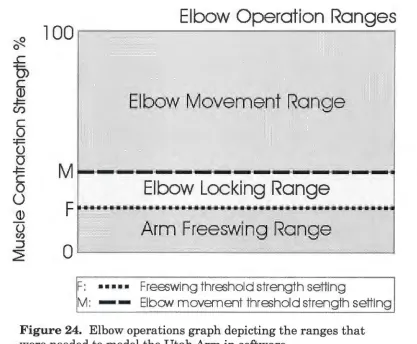
Elbow Threshold value (Fig. 24). If it was above that level, then the program
looked at the sign of the result to determine which way the motor would move.
If the difference was positive (biceps > triceps), the feedback would tell the user
that the arm was moving up. If the difference was negative (biceps < triceps),
then the user would be told that the arm was extending.
In the Unlocked State, the elbow was extended also by simply relaxing the
arm muscles and allowing the arm to drop into a Freeswing mode (Fig. 24). In
this mode, the arm swings without any resistance, much like our own arms
when we are walking. The Utah Arm takes the sum of the two signals (Channel
A and Channel B) to determine if they are relaxed below a certain level
(Freeswing Threshold) in order to relax the elbow motor [8]. Our software model
took the sum of the two channels and then verified that the result was less than
the Freeswing Threshold. If the value was below the threshold, then the user
was informed in the Training Feedback window (Fig. 20) that the arm was at
~
Elbow Operation Ranges
l 00
,---,---.
0
..c
0)
C
© ~
U)
·
Elbow Movement Range
C 0
~
0
0
~
C 0
0
Elbow Locking Range
©
0
(I)
Arm Freesw
'
ing Range
:J
~
0
..____ __
..._ ________
_
..._ __
__,
F: ... Freeswing threshold strength setting
[image:38.559.74.491.83.427.2]M: - - Elbow movement threshold strength setting
Figure 24. Elbow operations graph depicting the ranges that were needed to model the Utah Arm in software.
For the arm to switch from elbow control to
hand control, the elbow had to lock. The Unlocked
State also monitored locking to see when it needed
to switch to the Locked state. In the Utah Arm,
there are two conditions that must exist
simultaneously for the elbow to lock: (1) the elbow
has a load on it (elbow torque> 0) and (2) the elbow
motor is stopped (motion= 0) for a certain amount
of time. With an actual prosthesis, the arm has a
range of motion (ROM) of 135° (Fig. 25). Since the
forearm and TD have a certain weight, there is a
torque on the motor at almost every point in the ROM. For this reason,
Myotrain's simplified model assumed that there was always torque on the motor,
and that it was constant throughout the full ROM. In reality, the torque is not
constant throughout the ROM because the forces on the elbow will change as the
hand moves to different positions. It was not necessary to take this variable into
account in this experiment because there was no active graphical representation
of the arm present during the training exercise. Additionally, since proportional
control was not integrated into the model, the variable effects of torque did not
need to be taken into consideration.
Condition 2 for locking is met when the arm is in a position for a set
amount of time, called the Lock Threshold. Since there is a load on the arm,
there needs to be a contraction to hold the arm at a certain position-the user
does not relax completely for the motion to be zero. In the software model, this
range was determined by seeing if the arm was in the Locking Range (Fig. 26).
The locking range is between the Freeswing and Elbow Thresholds. In this area,
the arm will not move up (it is less than the Elbow threshold) and will not relax
(it is above the Freeswing threshold), so its motion is essentially zero and the
arm will lock if held in this range for about 1 second (Lock Timing).
The Myotrain software also checked to see if the difference of the
contractions was in the lock range (Elbow Threshold < difference < Freeswing
Threshold). If this condition was met for the amount of time set by the Lock
Timing Threshold, then the elbow locked and the arm model moved into the
Locked State for the hand to be controlled.
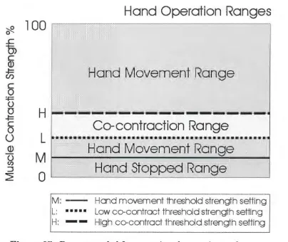
Locked State
In the Locked State, the hand is operational and the elbow cannot be
moved. The hand is more sensitive in its operation than the elbow because only
a 5µV difference in signal is necessary to make the hand move [8], but at least a
'2/2.
..c
0)
C (1)
~
U)
C
0
=-F
0
0
~ C
0
u
(1) 0
(/)
:J ~
100
M
F
0
F: ••••• M:
-T:
Elbow Lock
i
ng Graph
Time
(
s)
Freeswing threshold strength setting
Elbow movement threshold strength setting
[image:40.559.69.502.81.448.2]Tirne setting for elbow lock (,--1 sec)
Figure 26. Locking graph depicting how holding the arm in the locking range for a set amount of time locks the elbow.
the arm. If the difference of the EMG signals of the biceps and triceps is above
the Hand Threshold (at least 5µV), then the hand will either open or close (Fig.
27). Normally, a stronger biceps signal will cause the hand to close, while a
stronger triceps contraction will make the hand open [8] (Fig. 8). There is no
special resting or Freeswing mode for the hand in the Locked State. The hand
can manually be turned off to maintain a grip on an object, but when it is turned
on, the hand is opening, closing, or stopped. Proportional control of the hand
was not taken into account for the same reasons as explained above for the
~ 0 ..c
0)
C (l} -t= Cl) C 0 :.i:= 0 0 -t= C 00
(l} 0 (I) :::,2=
100
H
L
M
0
M :
-L: ••• •·•
H:
-Hand Operation Ranges
Hand movement threshold strength setting
[image:41.559.70.474.83.423.2]Low co-contract threshold strength setting High co-contract threshold strength setting
Figure 27. Ranges needed for operating the opening and closing of the hand. The unlocking, or co-contracting, range is also shown.
To switch out of hand control and move the elbow again, users must
unlock the elbow with a dual contraction of both muscles. The co-contraction is
used by some myoelectric arms as a means to transfer control from one motor to
the other [28]. The co-contraction has 4 parts to it (Fig. 28): (1) both muscles are
contracted together at a certain rate (Rate Threshold), (2) the sum of both
muscles goes above a high threshold, (3) the sum of both muscles goes below a
low threshold, (4) steps 1-3 occurs in a certain time interval (Time to Complete
Co-contract). A co-contraction is a quick contraction and relaxation of both
muscles. Some therapists describe the co-contraction as a quick clenching of the
•~ i l : -L:
Hi•··
H: . . . .
T:
Elbo
w
Unloc
k
ing
Graph
Hand movffilent threst1old strength setting Low m -contractthra;hdd strength setting
High co-cmtract tt1reshold strengtt1 setting
[image:42.559.70.448.82.472.2]Time setting for m-contrac1ion (
~
1 sec)Figure 28. Graph depicting the steps needed to
successfully co-contract opposing muscles to cause a
myoelectric prosthesis to unlock.
motor is deactivated, and the elbow motor is turned on. The user must raise the arm a small amount to disengage the metal locking pin to complete the
unlocking procedure.
In the software, while in the Locked State, Myotrain looked for a co-contraction where each signal was above the Co-contract High Threshold and
the rate of contraction was above the Rate Threshold. If these conditions were
out of Locked State. Upon relaxing and raising the arm, the arm model moved
back into the Unlocked State where the elbow could be manipulated.
Arm settings
The Utah Arm 2 can be manipulated by turning different potentiometer
dials inside the arm and hand (Fig. 29). The elbow dials do not affect the hand
operations, and vice versa. These adjustment dials allow the prosthetist to
modify the arm settings so that the arm will function optimally for each user.
Settings that can be
changed in the arm and
hand include biceps and
triceps gains and
thresholds, lock timing,
EMG filtering, freeswing
thresholds, co-contraction
rates, and muscle
differencing gains. Each
of these settings will
customize the arm to the
user.
In the software
model, users were able to
make some changes to the
[image:43.559.244.470.278.497.2]arm, similar to the actual
Figure 29. Hand circuit adjustment controls allow prosthetists to make modifications to the hand operations such as gain, rate, and
threshold.
Utah Arm. Arm settings could be accessed from the button bar at the bottom of
the screen (Fig. 19) or from the Edit Menu at the top of the main screen. When
settings were accessed, a window appeared, allowing the user to make
modifications to elbow and hand settings (Fig. 30). The Movement Settings
Figure 30. Arm settings could be manipulated in software to customize the arm model to the user. Settings could change both elbow and hand operations.
to lock the elbow could also be
modified in this area. Co-contract
settings for unlocking the arm
included modifications to the high
and low thresholds, rates for each
muscle channel, and timing needed
to complete the co-contraction. If
users wanted to revert to the
programmed defaults, then they
could push the Defaults button to
apply the defaults.
Settings were saved in a text
file in the user's folder for easy
access by a therapist or evaluator.
They were also saved in the CSV
file when each training session was
completed. Some of the arm settings were also displayed in the Training
Feedback window for easy reference (Fig. 20). If a user made changes to settings
during a training session, they were recorded in the data file. Evaluators would
be able to determine if the modifications to the arm were successful at helping
the user succeed at a certain task.
Training Procedure
No documented procedural standards for myoelectric prosthesis training
were found. Through correspondence with eight prosthetists and professionals
in the Orthotic and Prosthetic (O&P) field, only one said he used a standard
written training procedure to train a user to control myoelectric devices. The
other respondents stated that there was no set training procedure, but they gave
successfully teach individuals to use myoelectric prostheses and become
independent users. A training procedure that was common among some of the
prosthetists surveyed was Motion Control's training program for the Utah Arm.
This program is documented in Motion Control's Utah Arm 2 Handbook and in a
video called Training the Client with an Electric Arm Prosthesis. Most of the
training procedures used in this study for the Myotrain program are from the
Motion Control training procedure. Other training elements came from
suggestions received through correspondence with prosthetists and therapists
around the world.
Training setup and procedures
The primary goal of prosthetic training is to maximize the potential use of
the prosthesis in the client's daily life [9]. In training a user to successfully use a
myoelectric prosthesis, there are three main teaching procedures: signals
training, control training, and use training [9]. Practice is another important
part of training that needs to be used and emphasized during each stage to
ensure quick and successful use of the prosthesis. The user must practice the
procedures as much as possible for additional reinforcement and ultimate
success [9] [14].
Signals training
The first step in training an individual to use a myoelectric prosthesis is
to find optimal placement of the electrodes for muscle contractions. This is
important because finding the location of the most consistent and best
antagonist muscle groups will ensure a user can control the prosthesis
effectively. The prosthetist will make sure that the electrode sites are not
located in areas of hypersensitivity or where there is scabbing or open wounds
[9]. The EMG site testing is done by placing the electrode bar over a muscle
arms together, and then only the amputated arm. This helps the user learn how to contract the muscles that are needed and observe the signal on a monitor. Traditionally the signals are observed on a myotester such as the Myolab II, but this software trainer program allowed users to see their signals on the computer monitor.
In the Myotrain software, users chose the Test EMG Sites menu button (Fig. 17) and then were presented with three options for testing their muscle sites: Channel A, Channel B, or Both Channels (Fig. 31). They were tested on each channel separately to learn how to
contract the biceps and triceps separately and then tested on both channels to make sure that there was a good difference of signal between the two.
Figure 31. Menu used for
selecting either Channel A or B, or both channels to test for optimal EMG sites.
As good locations are found for muscle contractions, the user or therapist marks the areas in pen and then slightly moves the electrode bar (about 1 cm) until the best location is found [8]. Once one muscle group is located and marked, the antagonist muscle group is then located. The therapist is looking for the best difference between the two muscle groups, not necessarily the
strongest signal from each [8]. The user will be more successful if there is about 20µV of voltage difference that can be controlled between the electrodes-but lOµV will suffice. When the optimal sites are located for the electrodes, then controls training can begin.
Controls training
done using the Myotester to display the signals as users contract their muscles
in the appropriate control processes. Once the user is comfortable and able to
perform the simple operations of elbow and hand movement, the user is taught
use of the arm [9]. It is important to go from simple to complex and reinforce
each step with practice [9]. During controls training, the user will learn how to
move the elbow motor up and down, how to open and close the hand, and then
how to lock and unlock the elbow.
In the training software, users were able to learn how to use the arm, the
hand, or lock and unlock the elbow (Fig. 32). Instruction usually began with the
elbow motor, teaching the user to move it up
and down. During the Arm Up and Down
exercises, the arm would not lock. This is
similar to pushing the lock override button
on the Utah Arm to prevent locking during
initial training. This feature was added to
allow users to concentrate on the simple
task of moving the arm before worrying
about locking and unlocking the elbow.
Appropriate feedback was given to the user
in the Training Feedback window (Fig. 20)
when correct and incorrect arm movements
[image:47.559.55.512.238.557.2]were made during the learning process.
Figure 32. Menu options for
learning how to control and operate the myoelectric arm. Users were able to learn about the arm, the hand, and the locking and unlocking of the elbow.
Once satisfied with the arm procedure, the user was taught to open and
close the hand. This motion is similar to the bending of the elbow because it
entails contracting the same muscles as the elbow requires. Just like the arm
procedure, the Hand Open and Close exercise would not allow the elbow to
unlock if the user accidentally co-contracted. An inadvertent co-contraction
co-contracted. Other appropriate training was also given while opening, closing
and resting the hand.
After learning the hand operations, users were instructed how to lock the
elbow by stopping the arm in one location for a certain length of time (about 1
second). After learning the locking control, users learned how to unlock the
elbow with a co-contraction.
When all of these control
procedures have been taught to the user
and the user feels comfortable with
them, at-elbow trainees normally don a
myoelectric prosthesis and begin use
training with the arm. Trainees using
the Myotrain software were allowed to
practice (Fig. 33) their skills after
completing the Learn Procedures part.
During the practice options in the
Myotrain software, users were able to
practice the same exact procedures that
they learned during the Learn
Procedures portion of the program. In
Figure 33. Practice options for
the user to choose from after having completed the learning procedures of the Myotrain program.
addition, users could practice full control of an arm. This portion of the program
allowed them to see what happened if they accidentally locked or unlocked their
arm. The full control gave them a real-life example of the arm model and
allowed them to practice as if they were wearing a prosthesis. The feedback
given during the Complete Control exercise was positive and negative feedback
related to the way the user controlled the arm and hand. Some of the exercises
included in the Complete Control portion helped the user imagine scenarios for
controlling a real prosthesis. Using these scenarios, users could practice use
Use training
To accomplish the goal of prosthetic training, users need to be taught how
to use their arms in different situations so that it can ultimately be used in
normal daily routines [14]. During use training, the therapist or prosthetist
teaches the user how to use the arm and hand together for different tasks or
operations. An important part of this training includes showing the user how to pre-position the arm to pick up or hold an object with the artificial hand.
Pre-positioning means to place the arm in an appropriate position so that a certain
task can be performed well with both hands or arms [9].
Use training usually entails starting with basic use of the arm to do tasks
such as picking up and placing objects for pre-positioning and integrated hand
and elbow use. After learning basic integrated functions, the user is instructed
to work on other, more complex, everyday tasks like cracking an egg, hammering
a nail, getting bills out of a wallet, etc. This final part of use training leads the
individual into practicing activities of daily living (ADL) that are functional
activities specific to each individual. Practicing ADL procedures will help give
the individual a sense of accomplishment and realization of how to succeed at
doing normal daily tasks with a myoelectric prosthesis [9].
A user will normally work on use training once he or she is fitted with a
myoelectric prosthesis. The advantages of use training with a fitted myoelectric
arm are many. Users can get a true feel for how to run the arm and perform
tasks. They will have a chance to see how to use both arms and hands at the
same time. A computer simulation cannot replace the real experience of
practicing using a myoelectric prosthesis.
The Myotrain software program does not have use training integrated into
the training procedures because the best use training is done with the prosthetic
limb in place. Part of the program training touched on use training during the
practice and testing phase. In these parts of the program, users were instructed