Retrospective Theses and Dissertations Iowa State University Capstones, Theses and Dissertations
1-1-1980
A remote biological data acquisition system
Jonathon William Bredow
Iowa State UniversityFollow this and additional works at:https://lib.dr.iastate.edu/rtd Part of theEngineering Commons
This Thesis is brought to you for free and open access by the Iowa State University Capstones, Theses and Dissertations at Iowa State University Digital Repository. It has been accepted for inclusion in Retrospective Theses and Dissertations by an authorized administrator of Iowa State University Digital Repository. For more information, please [email protected].
Recommended Citation
Bredow, Jonathon William, "A remote biological data acquisition system" (1980).Retrospective Theses and Dissertations. 18068.
by
Jonathan :William Bredow
A Thesis Submitted to the
Graduate Faculty in Partial Fulfillment of the Requirements for the Degree of
MASTER OF SCIENCE
Major: Biomedical. Engineering
Approved:
Signatures have been redacted for privacy
Iowa State Univer·sity Ames, Iowa
1980
ii
TABLE OF CONTENTS
LIST OF SYMBOLS AND ABBREVIATIONS I. INTRODUCTION
II. BIOLOGICAL DATA TELEMETRY DEVICES CURRENTLY BEING USED A. Remote Devices Utilizing Only a Transmitter
B. Remote Devices Utilizing Only a Receiver or Both a Receiver and a Transmitter
III. DISADVANTAGES OF CURRENTLY USED BIOTELEMETRY DEVICES IV. A UNIVERSAL REMOTE BIOTELEMETRY DEVICE
V. EXPERIMENTAL PROCEDURE AND RESULTS A. Remote Device Receiver Design
1. AM Approach 2. Pager Approach
3. Superregenerative Approach 4. Weather Radio Approach
B. Remote Device Transmitter Design C. Receive -to-Transmit Switching VI. CONCLUSIONS
VII. BIBLIOGRAPHY VIII. ACKNOWLEDGEMENTS
IX. APPENDIX A
A. Low-Power Integrated and Monolithic Circuits Useful in Biotelemetry
1. The MC14046B as a Phase-Locked Loop
2. The MC14046B as a Voltage Controlled Oscillator 3. The Fairchild µA776 Micropower Op Amp
4. A Monolithic Micropower Command Receiver
X. APPENDIX B
A. Construction and Tuning of the JFET VHF Amplifier Shown in Figure 5
1. Construction Steps 2. Tuning
XI. APPENDIX C
A. Conditions for Oscillation of the Grounded-Base Crystal Oscillator
XII. APPENDIX D
A. Construction and Tuning of a Grounded-Base Crystal Oscillator
1. Construction 2. Timing
XIII, APPENDIX E
A. Operation of Transmitter Address Encoding and Receiver Address Decoding Circuitry
67
67
67 70
72
72
77
77
77
BO
82iv
LIST OF TABLES
"
Table 1. Characteristics of some current biotelemetry transmitters
Page
Figure 1. Figure 2.
Figure 3.
Figure 4. Figure 5.
Figure 6.
Figure 7.
LIST OF FIGURES
Block diagram of a typical biotelemetry system Frequency spectrum of a 4-channel AM-AM frequency multiplexed biotelemetry transmitter
Block diagram of proposed remote data acquisition device
Block diagram of an AM radio receiver
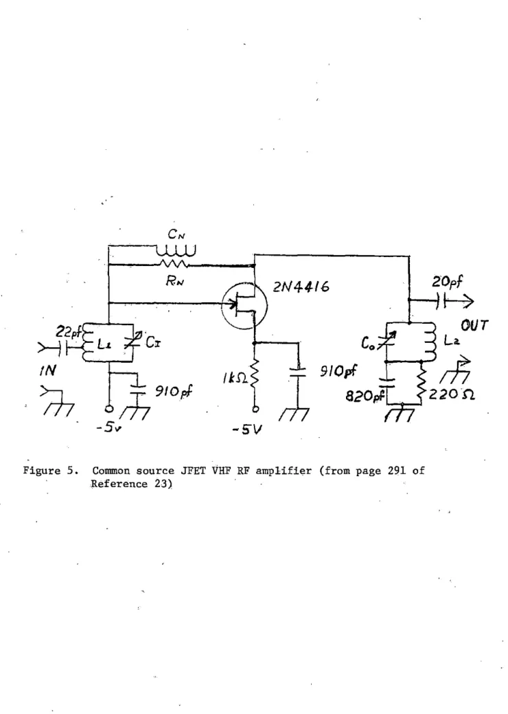
Common source JFET VHF RF amplifier (from page 291 of·Reference 23)
TM
RF circuitry of the Motorola Pageboy II 1 pager
Superregenerative detector constructed from common-base crystal oscillator and CMOS 4046 ph~se locked
loop I
Figure Sa. VHF crystal controlled superregenerative: detector from page 6.S of Reference 32
Figure Sb. Device of Figure Sa modified so that cMds 4046 VCO replaces astable multivibrator quencher :circuit
Figure 9. Weatheradio TM schematic ..
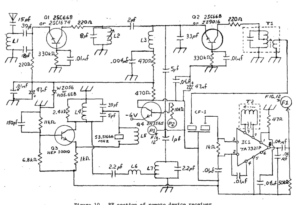
Figure 10. RF section of remote device receiver Figure 11. RF section of test transmitter
i
Figure 12. AF amplifier /FSK demodulator .of remote d~vice receiver '
Figure 13. Address encoding circuitry of test transmitter
Figure 14. Address decoding circuitry of remote
dev~ce
receiverFigur~ 15. Remote device transmitter
Figure 16. Block diagram of proposed remote device receiver/ transmitter with antenna switching amplifier
vi
Figure Al. Block diagram of MC14046B phase-locked loop IC 61 (from page 7-124 of Reference 20)
Figure A2. Block diagram of MC14046B being used as a phase- 63 locked loop (from page 7-128 of Reference 20)
Figure A3. Pinout for Fairchild µA776 micropower op amp IC 66 (from page 12-120 of Refe rence 18) and connection
of the µA776 as an inver ting amplifier
Figure Bla. 145 MHz cormnon- source JFET VHF amplifier from 68 page 291 of Reference 23
Figure Blb. 163.5 MHz common- source JFET VHF amplifier resulting 68 from modification of the circuit in Figure Bla
Figure B2. Experimental setup for determining tap points 71 (TPl and TP2) for inductor L
Figure Cl . Schematic of a grounded-base crystal oscillator 73 (from page 90 of Reference 12)
Fi gure C2. Overtone response of a quartz crystal (from page 30 76 of Reference 12)
Figure Dl . 53 . 51666 MHz grounded-base crystal oscillator 78 with output frequency tripler stage
A AM amp CB CMOS db DC ECG EEG EPROM FM FSK GI H hr Hz IC IF JFET k m MHz NADC Ni cad
LIST OF SYMBOLS AND ABBREVIATIONS
Ampere
amplitude modulation
amplifier citizens' band
complementary metal-oxide semiconductor
decibel
direct current electrocardiagram electroencephalogram
erasable-progrannnable read- only memory
frequency modulation frequency-shift keying
gastro-intestinal Henry
hour Hertz
integrated circuit intermediate f requency
junction field-effect transistor
kilo- orl03 (may be used alone or to form kA, kHz, kV, kW ,kn)
-3
milli- or 10 (commonly used to form mA, ms, mV, mW) 6
MegaHertz or 10 Hertz
vii:i.
op amp operational amplifier
osc oscillator
pf ,pF picoFarad or lD-12 Farads
PLL phase-locked loop
PM phase modulation
RAM random-access memory
RF radio frequency
s second
UHF ultra-high frequency
v
Voltvco
voltage-controlled oscillator VFO variable frequency oscillatorVHF very high frequency
w
Wattµ micro- or 10 -6 (commonly used to form µA, µF, µH, µV, µW)
I. INTRODUCTION
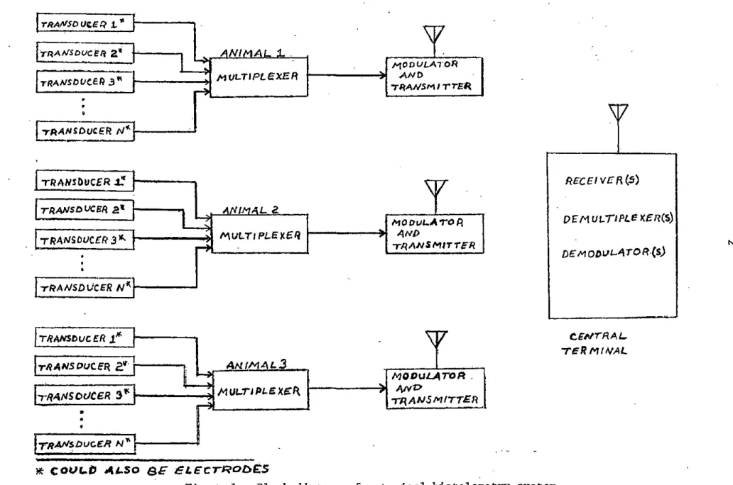
Many types of biological data, i.e., ECG, blood pressure, EEG, etc., can easily be obtained in a laboratory environment. However, in many instances it is desirable to obtain such data from animals in their
natural environment. A valuable method for obtaining such biological
data from one or more free-roaming animals is to use radio telemetry.
That is, each animal would carry, internally or externally, a radio frequency transmitter which would transmit a carrier frequency modulated
with the biological signal(s) of interest. Of course, so that the
signals of the transmitters do not interfere with one another, it would be necessary that each transmitter's carrier frequency be different.
The biological signal(s) for each animal could then be recovered by a conveniently located receiver (containing the appropriate demodulation
circuitry) tuned to the appropriate carrier frequency. In order to use
only one receiver for several animals, some type of frequency scanning receiver might be useful. After recovery of the biological signals
at the central terminal, these data could be stored or processed, as
desired, by computer. A block diagram of such a data acquisition system is shown in Figure 1.
The concept of the biological telemetry system is simple enough,
but the actual system components involved can be quite challenging to
design and construct. This is especially true of the transmitters. For
TRANSD ur;;.rU? 1..
lr~ANSDIJCE/i
2.,;TRANSOUCell .3" 1---...i MULTIPLt<XER
TRANSDUCER
J:!
TRANSOUCEA
a'
1----
LZTRANSDUCER N"-1---'
'TRANSDUCER J."' :
lrRANSOCJCE'~ 2~
ANIM:!ll.J~
~h-R4NSOUCER
3":
::..::
MUl..T,PLl!X~fl.• •
•
ITRAflSDtJCE:R N"';
~ cour..i' ALSO GE t:LECTROb£S
MODULATOR
I---~ AND
TltANSM 1-rrE~
MO DvL.A 'T'O A
1---.i A,NI>
Tl/,ANliMITTlfR
-
\7
MODULATOR.
.
ANDT~ANSMITiER
Figure 1. Block diagram of a typical biotelemetry system
RECEIV£R(S)
OEM U!../IPLE K&R(S)
N
Dt:MODVL"'\TOR-(S)
CENTR.AI..
should be considered in the design and construction of a biotelemetry
transmitter are:
1. Which type of modulation of the biological signal(s) onto the carrier frequency will produce the optimum combination of
high signal/noise ratio at the r eceiver and low power
consump-tion and small physical size at the transmitter?
2. How many biological signals will be transmitted from each
animal?
If more than one biological signal is to be transmitted using
one transmitter, then either frequency or time multiplexing of the biological signals will be required. Thus, additional circuitry will be required to accomplish the task of
multi-plexing, which will in turn increase the size and power consump-tion of the transmitter device .
3. What type of material will be used to enclose the transmitter? If the device is mounted externally to the animal, then the
cir cuitry and transducer must be kept from being exposed to
the weather. If the device is to be implanted, swallowed, or otherwise used int ernally, then the transmitter circuitry and
transducer must be protected f rom the harsh i nternal environment of the animal; more importantly, the coating of the device must
be compatible with the homeostasis of the animal, so that t oxi-city does not result.
4. What type of transducer(s) will be used?
4
types . The design and construction of the transducers, however,
is an art in itself.
S. What batteries are available?
What battery sizes are available at the desired voltage, and
what is the rnA-hr rating of the battery? The answer to these questions will determine the life of the telemetry device
once it has been placed on the animal. It may also have a
sig-nificant bearing on the physical size of the telemetry package .
6 . How much will the transmitted signal be attenuated if the
device is implanted?
Body t issues can greatly attenuate the transmitted signal ; the amount of attenuation depends on the carrier frequency being used . Generally, the higher the carrier frequency is , the
greater the signal is attenuated . 7. What carrier frequency is to be used?
The components to be used in the transmitter will be dependent
on the carrier frequency to be used; generally , the lower the
carrier frequency is, the larger the physical size of the
transmitter circuit components is .
These criteria apply to the transmitter device, but they would as
equally well apply to a receiver which might be mounted on the animal. The purpose for such a receiver will become apparent in the following three chapters . A small portion of this paper discusses a remote device
The remote device transmitter and receiver which are discussed in this paper are part .of a universal biotelemetry d.;;vice suggested by Professor Art Pohm. 1 · "This universal biotelemetry device. features
adaptability
to
various transducers, data filtering devices, amplifiers, etc., with a minimum of connections, and programmability (both centralan\! remote), so as to ·allow a variety of data acquisition and animal experimentation routines to be used. This would enable not only
bio-logical data monitoring but also controlled injections, ,electric shocks, etc., during data monitoring. The control unit of the proposed unit would be a single chip CMOS microcomputer such as the 87C48 curr,ently
availaJ?le from Intersil (15) which is a copy of the 8748 produced by
Intel. The 87C48 contains 1 K bytes of EPROM and 64 bytes of RAM' on
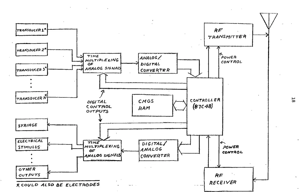
the chip. The block diagram of this universal biotelemetry device
is shown in Figure 3. This universal device will be further discussed in Chapter IV.
·As can be seen_ in Figure 3, this universal biotelemetry device utilizes both a receiver and transmitter. This 'paper deals almost
exclusively with the transmitter and receiver of the device and leaves the remainder of the unit design and construction to further research •
6
II. BIOLOGICAL DATA TELEMETRY DEVICES CURRENTLY BEING USED
L. • '
--A. Remote Iiev-ic-es Utifizing -briiy a Transmitter
This discussion by no means includes every remote biotelemetry
I
transmitter device that is now being used or that has ever been used
but is an attemJt to make comparisons of the characteristics of some
of the more current devices in order that some _generalizations about the characteristics of these devices can be made.
The first characteristic to be considered is the type of biological data being monitored. Table 1 shows characteristi~s of telemetry devices
being used by different experiment~rs, Owen et al. (22) monitored the
heart rates of birds. _Slater and Bellet (29) monitored the body temperatures
of submerged divers. Barr (2) used a telemetry device to monitor the
body temperatures of large numbers of caged rodents. Brach et al. (4) monitored wincerhardiness and temperatures of living plants by using
telemetry. Klein and Davis (17) used biotelemetry to monitor EEG, ECG, peripheral pulse, and arterial blood pressure of surgical patients. Peutsch (8) presented a 15-electrode totally implanted biotelemetry
unit for monitoring either various areas of the brain simultaneously or ~ore_localized areas in depth. Duncan et al. (9) used biotelemetry
to measure the temperatures of avian shanks. A Technical Note in Medical and Biological Engineering (30) presented a telemetry device
for remote monitoring of breathing pressures inside of a face mask
under different exercise conditions. Clark and Dowdell (5) used telemetry to
activity of smooth muscle of the GI tract of unrestrained conscious animals. As can be seen, the possible uses for biotelemetry are almost unlimited.
The second characteristic of the devices in Table 1 to be ·compared
is the carrier frequency of the transmitter. Of the telemetry devices listed in Table 1, Owen et al. (22), ·Klein and Davis (17), and Besseling et al. (3) used carrier frequencies within the FM radio band (88-108 Mhz). Of course, one of the primary reasons for using this range of frequencies
is so that the receiving device can be constructed from an FM band receiver. Slater and Bellet (29) used ultrasound as the carrier frequency · of their telemetry device because ultrasound transmission through.water
is more efficient than radio frequency transmission through water.
Brach et al. (4 ), Iv is on and Robinson (16), and Clark and o'owdell (5) also used VHF
carrier frequencies. Duncan et al. (9), and the experiments reported in the Technical Note (30) used 27 MHz as the carrier frequency, probably
becaus'e this frequency is in the citizen's band and also because a CB receiver can be used as part of the receiving device. Deutsch (8) indicated that for his.purpose, 20 MHz was about the most ideal carrier
frequency. Barr (2) used the AM radio band (530-1600 kHz) for his device, Some considerations which should be used for a given telemetry application include:
1. Is the remote device to be implanted?
Higher frequencies tend to be more highly attenuated by living
tissue than do lower frequencies, but circuits operating at higher frequencies tend to have smaller components.
Table ·1. Characteristics of some current biotelemetry transmitters
..
INV£Srt(JIToP, O'WtN 6T SLArFR. SARR (z.J Slf4C.H IYl'SON KLEIN ·D6UTSCN DUNCAN TECHNICA CLAR/(. ia£$SE£tll(i,
AL.(%21 8ELLF:T ANO !!:TAl.(4} ' l/OBl"ISON ",ANO D4VJS AND (fl} ETAL. (pJ . NC1Ni'3'21 loowoELL ANIJ CTAL. (J)
(29) (16) (/7) - (!j)
s-Jlo-C.ARRIEP, l1Js-1z.~ UL.TRA-
,,oo
.s6"lfl& VII~ ea~ 1oa z.o NH 'Z. 27 MHz. Z7MHz.
?
100-104l'REQUEl{CY
11Uz. $0UNO l'fl./:r. (CATSTAI (CRYSTAL) MHll!. Ml-I :r.
TYPE OI= FM (l>A1'A l=M (DATA
CAARIEfi >M
DIGITAL.LY AH OIGITALLY PM FM t:M FM AM Fr1 l!"M
MOIJIJLATION
ENCODED) ENCOOEO)
2.2 KH>:. Jo?.00 Ii•
,,oo-SUSCA·llfftl'R NONrf NONE NONE NONfi: NOIVE 3.5' K>I "- ADD£DTP 2. KHz 1200Hz NO Na HONE
l'R/fQUENCY S.O l<H;z. 6ACff
7.1> l<>lz. CH~NIYEI
TYPE' OF'
-1'
SrJ8CAllll I Ell 'NON& NCFIE NONc NONE NCINE /:M />IJLSE' l=M NONE. NON~
MOOULA,rJON RATIO
CX>
MOD.
TVPE OF TIME' 4•CllANll/i "·CW.llN/il 16-cll<tNl'l.ot.
SIGNAL /tONE NOf>ll!i NONI< i-'trJ<.TIPLE)( HONE l'"REQ. T•MC' NoNE NOrlE NOH'E T1"'1.E
HflLT"IPLEXlllG l'IULTll>i.EJ MflLTIPUiJ MULTIPLGX
BIOLOGIC.AL. SllR>ACE 800YTCl"I~ l/oO't TllMP. \/INTER- l•ECG IS-- AVIAN PllESSll/IE PH AND ELEGT.
DATA /3EING ECG OF OF llARD/Nns NOT 2•EEG f!l.oCTllOoES .SHANK VARIA"rtONl ~LUOFflOE'• Col'lrROL.
MOl#ITORED SIGNAL S llSMEllll~ CACl>D ,tjNI> TEMP. Gt.VEN 3-PU&.S6 /.lt>fAN TEMP. lfllSIOE 10/'I Cotti(. OP GX'
OF EllRDS DI.VEii ROor:nr.s Of: PLAJlrS 4-AJIT. BP (/RAIN S/G£ FACE•NAS. "f"RAC7"
l>OWER .1MA 4-0MW REL.. 6.oMA 3MA JV'PROJ(. 4
v.
RGL. Lt-rTl-GCt>N s UMPTIO. (t.1 .. ETll'IE l'OR 11..._A ·'ll(jll AT S'V AT 4·V. 3·.l>MA 12.0- HIGH (Nl'O • 111,,._A
)4PPROll. "rEMP. (DSC. .l2S' JotA
'TO DAYS) FILIJG-IN STAGE)
"""'I"' PG. Gatr ,pr;. 1011 ·4.,MOS PG.,..Stf.G9 PG. 105" PG. IS9 4 ·CMOS
CD,.,PONEN'rS ~f:
(29)
RI= {~ '(t~ (17)' -- .J'.oe" •• ,-~ (9) (30) CG)r.c..s,z-osc. o:sc. £.M JOBz..c..
...
,
..
11.t= DSC. . o~..,,MPI.C;
--It is simplest as well as most economical to use a frequency that can be received by a commercially available receiver. 3. What frequencies will be clear of interference? The telemetry
device should be designed to operate on a frequency for which no other commercial or private station can be received.
The third characteristic of currently used telemetry devices to
be considered is the type of carrier modulation used. Of the devices listed in Table 1, eight experimenters used frequency modulation, two
used amplitude mo.dulation, and one used phase modulation. Ivison and Robinson (1.6) argued ·in favor of coherently detected phase modulation, stating that it
satisfies the criteria of minimum transmitter power consumption, minimum bandwidth and operation over a short VHF radio link better than do the
other types of modulation. However, frequency modulation has advantages over both _amplitude and phase modulation. The biggest advantage that
frequency modulation has over coherent detected phase modulation is that the FM receivers are simpler and commercially available. Frequency modulation has ·advantages over amplitude modulation in that it tends to
be less distorted by noise than does amplitude modulation. Also, since
signal strength at the receiver input tends to diminish as the trans-mitter is moved farther from the receiver, the data signal recovered from
an AM signal, by the receiver, is dependent on the distance between the transmitter and receiver; on the other hand, data recovered from an FM
signal, ~y the receiver, is independent of the distance between the
transmitter and receiver since the signal frequency is unaffected by distance. With the integrated circuits which are now available, FM
10
Some of the telemetry devices listed in Table 1 utilize subcarriers. The frequencies of the subcarriers used in these devices is the fourth
characteristic to be considered. Of the devices listed in Table 1, only four of the experimenters used subcarriers. Three reasons for the use of subcarrier _frequencies can be pointed out by using some of the devices
in Table 1 as examples. Klein and Davis (17) U:sed four
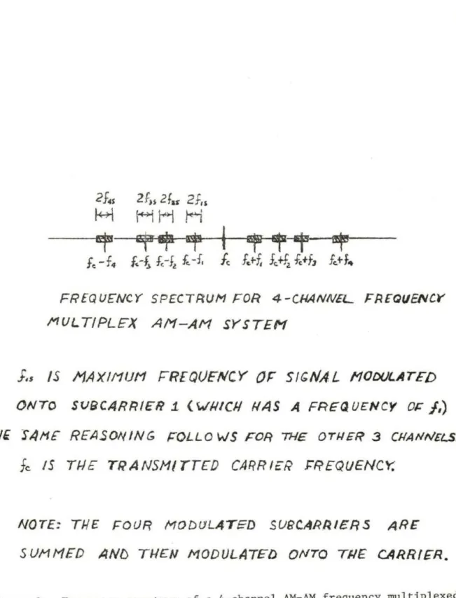
subcarrier-ftequen-cies modulated onto the carrier frequency as a means of frequency multi-plexing four channels of data. Figure 2 shows an illustration -of frequency
multiplexing for four channels_ of biological data (four biological signals) for an AM-AM system. A second reason for the use of a subcarrier is
illustrated by Deutsch (8) when time multiplexing 16 channels of
bio-logical data onto the carrier. A 3200 Hz signal was added to each channel as a reference signal. A third reason for using a subcarrier is found
in the device described in the Technical Note (30). This device employs
an 1100-1200 Hz subcarrier which is frequency modulated by the pressure variation_ inside_ a face mask under different exercise conditions.. This
subcarrier is essentially unaffected by the surrounding environment, -whereas the 27 MHz carrier will be much more greatly affected by the
environmental conditions, since the changes in inductance and capacitance due to. changes in environment will cause a much greater effect
(percentage-wise) on_ the small inductance and capacitance values found in the 27 MHz
circuitry than on the much larger inductance and capacitance values found
;ln the 1100-1200 Hz circuitry. With the subcarrier, therefore, noise due to changes in environment is practically eliminated.
The_ type of "subcarrier modulation used is the fifth characteristic
2f,.s
2fu 2far2f,,
H
HH
H
~~~~~~~~~~~tt~~
fc -f4
J:-t
f,-Jl
f..-f,
fc
f~+-f,J,+fz
fc+f,
f,+f ..
FREQUENCY SPECTRUM FOR 4-CHANNEL FAEGUEIVCY
MUL
T/PLEX A/1-AM
SYSTEHJ.s
IS l1AXl11UH
FREQUENCY
OP
SIGNAL
110D()LATEDONTO SUfJCARRIER 1. ( WlllCI./ llAS A FREQ U£NC'I Of:
J,)
(/.IE SAl1F REASONING /:OLLO WS FOR THE OTWEF? 3 CllANIVELS.
fc
15 T/.1£' TRANSMITTEDCARRlcR
~f?EQUENCY.NOTE:
TJ.1£ FOUR
MODlJLATE:D SU8CARIVERSARE
SUMMED AND
THENMODULATED ONTO
Tl./ECARRIER.
12
various types of subcarrier modulations are probably very similar to the reasons for using the various .types of carrier modulation. Therefore,
this wiil not be discussed except to mention that frequency modulation is again commonly used.
When more than one biological signal is being monitored, some type
of multiplexing must be used. The type of multiplexing used is the sixth
characteristic. of the telemetry devices listed in Table 1 to be discussed. Of the four devices listed in Table 1 which monitor more than one
·biological ~ignal, only one device utilizes frequency multiplexing; the
others utilize time multiplexing. An example of an ·AM-AM frequency
multiplexing scheme was shown in Figure 2. A time multiplexing scheme would not send a continuous signal of each of the biological signals
being monitored. Instead, for an N-channel unit, the following ,time sequence·woU:ld occur: First, the channel 1 data would be sampled and
transmitted, then the channel 2 data would be sampled and transmitted. Then channel 3, channel 4, _etc., and finally channel N. This sequence would occur continuously at a rate which would be several times the
highest data frequency of any of the channels. Considering the components
which are now available, it seems that time multiplexing would probably be simpler than frequency multiplexing due to the filtering that is
required in demodulating a frequency multiplexed signal.
The sev.enth characteristic of the telemetry devices lis,t,ed in Table 1
to be discussed is the power consumption. Unfortunately, the power
simpler devices by Owen et al. (22), Barr (2), and Duncan et al. (9) consume very small amounts of power (< 1 mW). Surprisingly, the six-channel time multiplex device by Besseling et al. (3) draws only 177 µA at 4.5 v (N .8 mW). With the CMOS devices and micropower op amps which are now available, it is possible to build fairly complex low-power
telemetry devices.
The final characteristic of the telemetry devices listed in Table 1 to be discussed is the amount of parts necessary for the telemetry
device. Not all of the devices are considered, but only those which were the simplest single and multiple channel devices found. The other circuits can be compared by going to the references. The simplest telemetry devices are those by Owen et al. (22) and Barr (2). These
devices consist of an RF oscillator as the main component. The 16-channel time multiplex device by Deutsch (8), however, requires 4 CMOS ICS,
l-LM308 op amp, and an RF oscillator as the main components. Likewise, the six-channel time multiplex device by Besseling et al. (3) uses 4 OiOS ICS, 2 micropower op amps, and an RF oscillator as the main components. These are not enough data to make generalizations, but it should be intuitively obvious that a multi-channel device requires more components than a simple single-channel device. The size of the multi-channel device will therefore probably be larger than a simple single-channel device.
14
B. Remote Devices Utilizing Only a Receiver or Both a Receiver and a Transmitter
Descriptions of three recent remote data acquisition devices, which utilize only a receiver or both a transmitter and receiver, were found in the literature. One such device is presented by Cupal et al. (6) which utilizes a 570 kHz receiver as part of a biotelemetry repeater to be used on a large wild game animal. The repeater, which is mounted on the neck, receives biological data from an implanted 570 kHz transmitter
and retransmits it on a VHF carrier to the central terminal. Another remote device which utilizes a receiver is presented by Guberek et al. (14).
This receiver is part of a remote controlled coronary artery occluder which is used to study cardiovascular disease. Finally, Hudson in (10) presented a receiver to be used as a power switch for an implanted tele-metry transmitter. When a radio frequ_ency command is transmitted from
III. DISADVANTAGES OF CURRENTLY USED BIOTELEMETRY DEVICES
The biotelemetry devices discussed in Chapter II are useful for the applications for which the"' were constructed; however, these devices
(with the exception of the device by Cupal et al. (6) which has charac-teristic 5) lack the following, sometimes desirable characcharac-teristics:
1. If the telemetry transmitter device moves out of range of the receiver or if the telemetry transmitter fails, the device on the animal should be capable of storing biological data long enough for the broken radio link to be resoored.
2. The telemetry device on the animal should be able to do simple statistical analysis on the data so that the transmitted data can be minimized or eliminated (so that only necessary data are transmitted).
3. The remote device should be remotely programmable so that the data monitoring and/or experimentation routines can be altered from the central terminal.
4. The circuit connections of the transducers to the remote device should be minimal s.o that a wide variety· of numbers of biological data signals can be monitored with a minimum of wiring connec-tions or disconnecconnec-tions.
16
6. All telemetry transmitters should be capable of operating on a single frequency in order to reduce system design requirements
IV. A UNIVERSAL REMOTE BIOTELEMETRY DEVICE
Since the telemetry devices discussed in Chapters II and III lack the desirable characteristics listed in Chapter III, a universal telemetry
.device which incorporates a single chip CMOS microcomputer controller, such as the Intersil 87C48 (15), is proposed; this device would at least
partially fulfill the list of desirable characteristics given in Chapter III. This device was mentioned briefly in Chapter I and is shown in block
diagram form in Figure 3. No estimate has been made for the power
con-sumption of this device. However, micropower op amps and other low-power
devices (such as small signal VHF and UHF transistors) are available for
its construction; this should allow the power consumption of the entire device to be tolerable if the unit is mounted externally to the animal.
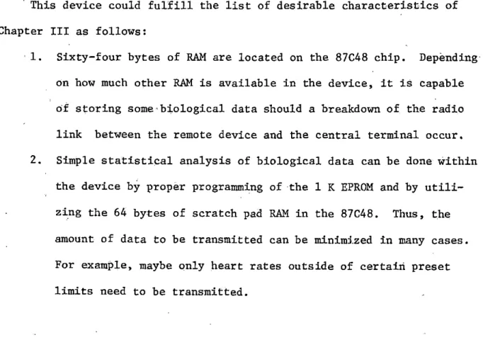
This device could fulfill the list of desirable characteristics of
Chapter III as follows:
· 1. Sixty-four bytes of RAM are located on the 87C48 chip. Depending·
on how much other RAM is available in the device, it is capable of storing some·biological data should a breakdown of the radio link between the remote device and the central terminal occur.
2. Simple statistical analysis of biological data can be done within the device by proper programming of the 1 K EPROM and by
utili-zing the 64 bytes of scratch pad RAM in the 87C48. Thus, the
amount of data to be transmitted can be minimized in many cases.
\
17
TflP,NSDuc£R 1." Rf:'
.
TRANSMITTER
-T"RANS ouc£R 2~
•
•~-
,...
~ 'rl ME ANALOG/ POWE.Ii
1--3 M<IL TIPL{f X!NG
-
-
CONTROLr-!
01' - l>IGITAL"
ANALOG Sl!'NALTRANSL•IJCE.11 3 r--.l CtJNVE R,1£ R
~--Ir
-•.
•.J
"
--TRA~.SDVCER N
DIG/ 7"AL CMOS ;---\ C OtlTRO LL ER
CONTROL
RAM
\-/_
(87C48)
ovrpurs
i
SYll!NGE ,
l
f
•..
I
E.LECTlllCAL TIME DIGITAL/ ~1-'.=
Ml/LT/PL EXI NG POWERSTIMVLUS
o~
/
••
ANALOG \ CONTllOL• .l\J\/ALOG SIGf'lllfS CONVFRTER '
•
....,...
•
'
OTHER
' OVTPVTS
Rr=
Ji( COVLO ALSO 8E ELECTR.OC>ES - -- - - - RECEIVER
3. Again; depending on how much RAM is present in the remote device (in addition to the 64 bytes of RAM on the 87C48 chip);
the device can be remotely programmed to carry out a variety of data monitoring and/~r experimentation routines. Several routines
could also be stored in ·the 1 K EPROM and called remotely .•
4. It should' only be necessary to connect or disconnect transducers or ,electrodes to the device in order to add or subtract biologi-ccal .signals to be monitored, since the multiplexing scheme can
be altered by progralllllling the 87C48 (minimize hardware altera-tions).
5.· Since this device already incorporates a receiver, it should be ·relatively easy to program the remote device to receive·~and.
retransmit signals from a telemetry device located w:ii:hin th.e body.
6. Only a single carrier frequency is necessary for a biotelem~try system consisting of a large number of these devices since they
can be addressed individually by the central terminal with a binary code.
As was mentioned in Chapter III, sometimes the above characteristics
ar!'! not necessacy; then it is better to use the simple telemetry devices listed in Chapter II, since a larger size and greater power consumption is necessary for the universal biotelemetry device. For many data
acquisition' systems, however, the versatility of the universal biotelemetry deviee and the other advantages 'that it has over the simple telemetry
20
V. EXPERIMENTAL PROCEDURE AND RESULTS
A. Remote Device Receiver Design
The experimental procedure which was followed throughout the receiver
design research.was divided into four parts~ This was not a result of
choice ·at the ·beginning of the project, but a result of other considera-tions which came into play during design and experimentation. The fqur
parts of the experimental procedure are the AM approach, the pager
approach, the superregenerative approach, and the weather radio approach. Initially, it was decided that .the superregenerative approach was
inadequate due to the possibility of the units interfering if two animals carrying receivers tuned to the same frequency came close to one another.
Thus, AM was initially considered to be the best approach in terms of
power consumption and simplicity.
1. AM Approach
An amplitude-mopulated signal consists simply of a carrier frequency,
the amplitude of which is the data signal.
Briefly, an AM radio receiver (AM receiver is shown in block diagram
form in. Figure 4) functions as follows in recovering the data signal from a transmitted AM waveform.
The received signal is first amplified and then mixed with a local
oscillator signal (a sine wave of frequency fo) such that signals of
fr~quency fo + fc and fc - fo (fc is the received carrier frequency) are
\1
7
R~ .
MIXER
AMP..
h
.LOCAL
osc.
-
/:'ILTER
-
-
IF
A/'f
P
.
~1D£Tf"CTOR ~
RECOVERED
DATA.
22
is then amplified in the IF amplifier and finally the data waveform· is recovered from this signal by some type of AM demodulator, such as
an envelope detection circuit which determines the amplitude of the signal (that is, the data waveform).
The first circuit of the AM receiver to be experimented with was the input amplifier. The circuit which was used is a modification of the JFET VHF common source amplifier shown on page 291 of the Radio Amateur's Handbook (23) and is shown in Figure 5. (Modification of this existing circuit resulted in both a savings of time and a better amplifier than would have resulted had .the amplifier been designed from scratch. This circuit modification approach was thus followed throughout the remainder of the research.) The construction and operation of this circuit are discussed in Appendix B. After adjustment of the input and output tuned circuits of the amplifier, a gain of approximately 16 db was attained at 150 MHz (150 MHz was chosen as the operating frequency because it is a clear frequency in Ames, Iowa.) This circuit will again be discussed in Section 4.
The second circuit of the AM receiver to be constructed was the' local oscillator. Since a very frequency-stable receiver was desired, it was decided to build a common-base type crystal oscillator very similar to the one shown on pages 96 and 97 of the crystal oscillator book by Frerking (12). This oscillator was supposed to operate at 149.9 MHz so that the intermediate frequency would be low enough so that micropower op amps (see Appendix A) could be used as the heart of the IF amplifier.
Rw
L.1.
C:r
;j7
910,J
-5v-2N4416
lkSl
9/0pf
20pf
t--1~
OUT
La.
24
of how the crystal and crystal oscillator circuitry function. Appendix C
gives a brief description of how a crystal oscillator functions. For a more detailed description, see Frerking (12). For a description of the construction and tuning of a crystal oscillator, see Appendix D.
After a lack of results with the crystal oscillator , work was begun on the mixer stage of the AM receiver. However, shortly after this work
was begun, a conference of the Solid State Affiliates was held at Iowa State University. After a presentation of this device at the conference, it was stated by a number of representatives at the conference
(unfor-tunately, the names are not known) that the AM approach is probably not the best. They stated that low-power components for FM receivers (such
as pager components, CMOS PLLS, etc . ) are readily available and that FM connnunications have some major advantages over AM connnunications.
For example, AM transmissions are more affected by noise than are FM
transmissions . Also, AM signals tend to fade; thus, the true biological signal(s) being received may be distorted by the change of strength of the
transmitted signal which may occur as the animal is moving toward or away from the central terminal unless precautions are taken to correct
for this. FM signals, on the other hand, will either be detected or
not detected by the receiver since the data is encoded in the frequency rather than in the amplitude of the carrier signal . The FM approach was
thus determined bo be the best. Again, modification of an existing device was the approach decided upon. At this point, the existing device which
2. Pager Approach
The Motorola Pageboy II™ pager schematics and general information 1
about this device were obtained from Mark Grootveld. This pager draws only 3.8 mA from a 1.45 V battery when on standby (~5.5mW). The schematic
of the circuitry" of this device is shown in Figure 6. (Al, A2, A3 and A4
represent hybrid circuit modules.) This· circuit is intended to function
_approximately as follows. The RF input amplifier (Block Al) receives the transmitted signal and amplifies it by 11.5 db. This signal is then
mixed with a local oscillator signal (Block A2) of frequency such that the difference (transmitter carrier frequency - local oscillator frequency)
signal has a frequency of 17.9 MHz. Thli:s signal is then amplified by about 23.5 db in module A2. At the output of the high conversion module (Block
A2), the 17.9 MHz signal is passed through a six-pole crystal filter in. order to reduce the bandwidth of signals around 17.9 MHz which are also
passed; this both improves selectivity and greatly attenuates images that might be produced when the 17.9 MHz signal is mixed with the 17.935 MHz local oscillator signal of module A3 to produce a 35 kHz signal output.
The signal suffers 3 db loss through the crystal filter, but is amplified by 14 db in the low conversion module (Block A3). Finally, the 35 kHz
signal is amplified by 14 db and FM-demodulated (Block A4) to retrieve the.audio information which was originally transmitted.
It was decided originally that two identical receivers should be
constructed from the Motorola .Pager parts. The complete pagers would' have cost approximately $250 each. Therefore, it was decided to order two
1 .
x
t2pf18,.fr
15'
+
BTLL4-
L56
A :3
1..0W C.Ol>J V~RS ION
6
6
6Bpf
ih
I•
Figure ·6. RF circuitry of the Mot_orola Pageboy II· pager TM
R2
l.SkJL
2
~UOIO
PAEAA1P
. 3
2
ACIOIO
hybrid modules of each of the modules Al, A2, A3 and A4 and two of the remainder of the RF circuitry shown in Figure 6. Unfortunately, it was not
a simple task to make the receivers work once the parts were obtained. To begin with,· when the parts were ordered, the s·ix-pole filter between
the high converter and low converter was not available. If this filter is not used, then there is no reason to use the low conversion module (A3).
That is, without this filter, or one similar to it, an image frequency will amost certainly be present and the selectivity will be poor.at the output of the low conversion module (A3). Thus, it would be just as well to use a higher local oscillator frequency in the high conversion.
module (A2) such that the signal output from this module has a. ·.frequency of 35 kHz. To improve the selectivity, this 35 kHz signal could be
passed through an active bandpass filter. The approach to building an
.FM receiver from the pager parts was thus begun with the intent of using
modules Al and A2 of the pager circuitry and micropower op amps and CMOS PLLs' in the IF amplification· and FM detection circuitry. (See Appendix. A for a description of these devices.)
·The first part of this receiver which was constructed was the input RF amplifier. This was constructed by connecting discrete components to module Al as shown in Figure 6. The maximum.gain of this c~rcuit was
obtained· at 145 MHz instead of·at the desired 151 MHz. In order .to try to move the maximum gain point to 151 MHz, C33 was reduced to 39 pF;
however, this caused oscillations to occur. C31, the neutralization capacitor; was increased to 2.89 pF in an attempt to stop the
28
point to increase to 146-147 MHz. It was discovered that by increasing
C31 to 5.09 pF, the maximum gain point was increased to 151 MHz.
After the input amplifier stage was made to function, the next step was to construct the circuitry around the high conversion module (A2)
and try to make the crystal oscillator in this stage oscillate at the crystal frequency. The oscillator in this module was designed to operate at one-third the frequency of the desired local oscillator signal. The
manner in which the local oscillator signal is obtained is to tune the crystal oscillator so that it is overdriven, thus producing a distorted
oscillator waveform rich in odd harmonics, and to filter out the third
harmonic s:j.gnal by using the tuned circuit, consisting of C9 and L4, tuned to resonate at three times the oscillator frequency. Assuming that
the output signal of the h:igh conversion stage is to be 35 kHz, and that the transmitted carrier frequency is 151 MHz, then the crystal oscillator
should oscillate at (151 + ,035)/3 = 50.345 MHz. The oscillator was never made to oscillate at the crystal frequency even by adjusting CS,
C9, ClO, L4, LS and R2. Part of the problem could be that crystals not normally used in the device were being tried because an error was made in specifying the crystals on the original order. Since the parts took
six weeks to arrive, it was decided that a new order for crystals would not be made and thus other crystals were tried.
It was hoped that by using an intermediate frequency of 35 kHz that the IF amplifier could be constructed from simple cascaded inverting
the cost of the receiver since each of the four modules in Figure 6 .cost
approximately $25.
After more frustration with the high conversion module (A2) and after consideration of the cost of the hybrid circuit modules, the
pager idea was finally abandoned. The estimated cost of each receiver (using only modules Al and A2 of the pager circuitry) would be a minimum
of $60. For a research experiment which would incorporate a large number
of these remote data acquisition .devices (Figure 3), the receiver cost alone would be·almost prohibitive. In addition, this $60 receiver would
have rather poor· selectivity due to the absence of adequate filtering. After consultation with Joe Riley, 1 it was decided that the remote
d~ta acquisition device shown in Figure 3 would almost certainly have to
remain external to the animal beeause of the large number of connections which would be made to the animal when monitoring a large number of
biological signals. Since the device would be external to the animal,
power consumption and physical size were not as confining restrictions
as was originally thought. Therefore, it was and still is felt that there is a better approach to the receiver than using pager parts.
3. Superregenerative Approach
Joe Riley suggested the use of a modified commercially available
FM receiver for the remote device.. Before beginning this approach, it was felt that construction of a superregenerative device might be
l Joe Riley is an electronics engineer at the National Animal
30
worth a try before going on to the modified FM receiver approach for
the following reasons:
1. Information about superregenerative devices was found which
indicated that_ th~ possible problem of receivers interfering,
mentioned at the beginning of this chapter, might be overcome by incorporating a well-neutralized RF·input amplifier prior to
the superregenerative stage, to block superregenerative stage oscillations from reaching the antenna, and thorough shielding
of this superregenerative stage, to prevent radio frequency
radiations.
2. The propose(! superregenerative receiver would be smaller than the·
modified FM radio device because it would require fewer components. 3. The proposed superregenerative receiver would consume approximately
1/2 the power of the modified Weatheradio™ of Section 4.
It was hoped that the superregenerative stage could be used .as an FM demodulator. However, the manner in which this device operates makes
it to be nearly an AM demodulator. The superregenerative stage functions approximately as follows. The signal from the antenna or from the input
amplifier.is fed into the superregenerator stage and amplified. The
amplified signa:[. is fed back into the input of· the superregenerator stage and amplified again. The number of times- that the input signal is
ampli-fied is determined by timing circuitry which controls DC bias to the
transistor of the RF oscillator part of the stage. After the preset
The timing circuitry which controls this DC bias can be adjusted so as to
achieve the desired compromise between sensitivity and selectivity.
As was mentioned above, it was thought that by using a well-neutralized RF amplifier as an input stage to the superregenerator stage and adequate
shielding of the superregenerative stage, that interaction between receivers
could be prevented·. The circuit which would have been used as the input amplifier is shown in Figure 5. (The construction and tuning of this
' amplifier are outlined in Appendix
B.)
However, it was not possible:to neutralize this amplifier to the extent that would have been desired; This 'will be discussed more in Part B.The next circuit to be constructed was the superregenerator stage. It was planned that FSK-AM transmission would be used such that a 400 Hz
AM signal would represent a binary 0 and that a 1200 Hz AM signal would represent a binary 1. · Thus, the output of the superregenerator stage
would be either 400 Hz or 1200 Hz. (The audio amplifiers· and demod~lators
which would have been used to convert the output signal of the superre-1 generator stage to a binary 0 or. binary 1 are the same as were used for
. . TM
converting. the output of the Weatheradio FM Detector in Section 4 and
are shown in Figure 12.) In the actual design and construction of the superregenerator stage, the first approach was to build a slightly modified version of the common-base crystal oscillator shown on pages 96 and 97
of Frerking (12) with VCO output of the CMOS 4046 connected to the base of the oscillator transistor to provide the quenching signal
(amplifica-tion control men(amplifica-tioned earlier); the quenching signal frequency could
32
for construction details and function of the common-base crystal
oscillator and Appendix A for construction details for using the 4046 as a VCO or PLL.)
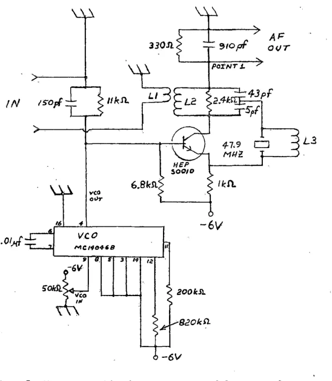
The frequency range of the VCO is determined by two resistors and one capacitor connected externally to the,4046 and were initially chosen so that a frequency range of 30 kHz to 150 kHz could be used. The circuit of this superregenerator stage is shown in Figure 7. As can be seen, the input signal is inductively coupled into the tuned circuit of the commort-base oscillator. The 910 pF capacitor, c~nnected from point 1 to ground, acts as a low impedance to the transmitted carrier frequency but as a .high impedance to the 400 Hz or 1200 Hz signals modulated on to the
carrier signal. The tuned circuit (containing L2) acts as a high impedance to the transmitted carrier frequency and as a short to the low frequencies. The transmitted data can thus be recovered across the 91.0 pF capaci.tor. The oscillator was operated at 47.9 Miiz, since crystals near this frequency are standard and available. The superregenerator stage was then tested with a transmitter also tuned to 47.9 Miiz and amplitude modulated with a 400, Hz or 1200 Hz sine wave. The results were not successful, although the crystal oscillator functioned properly.
The second superreg~nerator device tried was a modification of the
~1opf
Al=
330.!I. O(JTPO'I:NT J..
II
k.Sl.
LI:i..,43pf
!N
1sopf
2.41:s;,r
4-7.9
M/.ll
HEP $0010
6.BkSl
/Id) ..vco
o"1"
'~ 4
-61/
.01.J/
vco
,..,Clf04-'B II
3 '~ 1;,
200/dl.
. 820lc!J.
-6V
Figure 7. Superregenerative detector constructed from common-base crystal oscillator and CMOS 4046 phase locked loop
34
- Vee.
3.3kS'l. • 001
Jol.f
. 02 ••
J
!=ILT€R 01 2N71f
• OOlµf
A/: AHPL!FIEf/
OVTPVT
Figure Ba. VHF crystal controlled superregenerative detector from page 6B of Reference 32
•
.01,.,f
vco
OOT
VCQ II
MC.140468
-6v 9gS"31~
-bV
-6V
320.n
3.3kSl.
loot~F
920kfl 2001c S'l.
Cl
4-7.9Milz
FIL. TER
AF
AMPLlrtcR,.
OUTPUT
transmitter as was used for the device shown in Figure 7, the
superre-generator stage shown in .Figure Sb did not function. With less than desirable results obtained with the input amplifier and the frustratlons
found in trying ·to make the superregenerator stage function,. it was thought that time could be better spent in building a receiver from a modified FM radio. It still seems, ·however, that the superregenerative
detector would show some promise as a receiver in a biological data · ~
acquisition system, due to its simplicity, if the problems encountered with the input amplifier and superregenerator stage could be overcome.
4. Weather Radio Approach
·A.search was made for an inexpensive FM receiver operating as nearly
as possible to the desired 150 MHz. The device chosen is the Radio Shack Mini.WeatheradioTM. The schematic for this device is shown in Figure 9.
Notice how simple this device is. It consists of an input RF amplifier
stage, a variable frequency local oscillator, a mixer·stage, a crystal filter at the output of the mixer stage, an IF amplifier/FM Detec.tor' IC,
and an audio amplifier IC, the output of which feeds into the speaker.
The device is. designed to receive the frequency range of 162.4 to 162.55 MHz.
(U.S. Weather Bureau stations broadcast continuous weather information
on 162. 55, 162. 4 or 162. 4 7 5 MHz.) The manner in which this .device operates is approximately as follows. The received signal is amplified and then mixed with a local oscillator signal, the frequency of which is such that
the output signal of the mixer is approximately 4 MHz. This signal then
SCHEMATIC DIAGRAM
QI 2SC668 or 2SC1674
.
• ·1-1 I I I.
uI VR-2 I ·1011!1
I ~1·
Q2 ZSC&68
or JE9016
~
"l
"
""
03 2SC'&e or JE901b
-
"
50115 A13 10QI{ AIS 3JOKs ~1
•
---~
NOTE (I_) AU. RESlSTANCE VALUES ARE INDICATED JN "OHM .. (K.,1dcff,t0
,Mzlcf01-M). { 2) AU. .CAPACJTANCE VAUIES ARE ·tNQICATED IN .).IF ... (Palci1pF):
·i· MAY VARY FROM l.llllT TO UNIT FOR EEST PERfQRMA.t«:E.
R-16 47
~ ~
0
e
"'"'
VR-1
-Figure 9. Weatheradio™ schematic
c2a. '· 7/IO
SP
""""
~
to the output of the crystal filter), to the IF Amplifier/FM Detector IC, the output of which is the audio information which was frequency-modulated onto the transmitted carrier. This audio signal is further amplified and
fed into a speaker.
In order to make modification of the Weatheradio™ as easy as possible,
it was decided to operate the remote device near the weather band. In
this way, the tuned circuits of the input amplifier would not need altering. The only alteration which would be necessary would be
modifi-cation or replacement of the local oscillator. As a preliminary test of the WeatheradioTM, the minimum operating voltage and the corresponding
current drain were determined. At 5 volts, the radio was still fairly sensitive, but below five volts, the sensitivity dropped quickly, probably
because the voltage became less than the minimum operating voltage for the IF Amplifier/FM Detector IC. Without the audio amplifier present in the circuit , it was found that the device draws only 8 mA at 5 volts
(N 40 mW).
The construction of the remote device receiver was begun by performing
the only modification of the RF circuitry of the Weatheradio™ necessary. This was done by removing the VFO circuitry (enclosed by dashed lines in
Figure 9) and replacing it with a common-base crystal oscillator containing a frequency tripler output stage . (The operation and construction of
common-base crystal oscillators is discussed in Appendices C and D. ) The crystal used in the oscillator was constructed to be resonant at 53 . 51666 MHz. Thus , the local oscillator frequency used in the device
is 3 x 53.51666
=
160.550 MHz, and the operating frequency of the receiver38
circuitry with, the VFO replaced by the crystal oscillator is shown in ·
Figure 10. The idea for the frequency tripler stage used in this oscillator
was taken from the crystal oscillator used in the high conversion module TM
of the Motorola Pageboy II pager. This frequency tripler stage
func-tions as follows' The tuned circuit of the grounded-base oscillator.
is tuned for crystal oscillation such that the output waveform becomes as distorted as possible. The third harmonic of the fundamental oscillation
frequency is then present in the waveform and is removed by passing the
signal through a bandpass filter tuned to three times the oscillator frequency and into the lower few turns (near ground) of the inductor of
a parallel-tuned circuit tuned to three times the oscillator frequency. The output is. then taken from the top of the parallel-tuned circuit through a high impedance (in this case, a 1 pF capacitor) and is nearly
a pure third harmonic of the oscillator fundamental frequency. With a
SQQ load at the output of this tripler stage, a sine wave of "' 100 mV peak-to-peak amplitude at 160.550 MHz is output.
As was mentioned earlier, the operating frequency of this device is 164.6 MHz. Unfortunately, it was found that this device also receives
the image frequency· of 156. 6 MHz. However, this has not caused any
problems .yet, and it does not appear that any such problems will result.
Before the remainder of the receiver circuitry was built, the LM3S6 audio amplifier IC was replaced as a convenience to the design process. The sensitivity of the circuitry shown in Figure 10 was then found to be
"' 20 µV.
It was hoped that the next step of the remote device receiver
ISO
pf
b.8kSt
,
__.Q/,qt
Q~
HE/' SOOIO
/kfL
L3
.oo4l 47o
.o'l,
+
'-17,..f
2.2pf- . O!,.f
I I
40
4mA at 5 volts, with micropower op amps and.'CMOS devices .. However, the micro-'
power op amps and CMOS devices which are.currently available will not.
operate at 4 MHz, the frequency at which the crystal bandpass filter also operates.
The next step in the design of the receiver was to rebuild the VFO
circuit (which was originally the local oscillator in the Weatheradio™)
as a test transmitter. This transmitter is shown in Figure 11. Notice
at the base of .the transistor of this VFO the presence of a
voltage-variable capac;,tan"e diod~ which can be used to frequency-modulate the VFO.
That is, when the voltage from the cathode of this diode to ground is
varied, the frequency of the oscillator changes because the capacitance present ~cross the diode changes. By applying a signal voltage from the
cathode of-the diode to the ground, the oscillator is frequency modulated.
For this particular application, the linearity of the FM signal is not
crucial. The thing that is crucial is that the frequency shift be
great enough so that t.he FM Detector in the receiver circuitry can detect it. The frequency shift of the transmitter can be adjusted by varying
the voltage amplitude of the signal applied across the voltage-variable
capaci·tance diode. The test transmitter was first used with a simple
sine wave input which was var.ied from about 400 Hz to 2 kHz. ·The 400 Hz to z·kHz signal was clearly heard from the speaker of the receiver. This
was an attempt to adjust the transmitter to the proper frequency aI\d to
determine if the frequency modulation technique was working. The next
. lleP RZ!iOC>
l.2k!il
JE90l6
0
.01,.JP1
1--.,___.._..
1---'+-....,'----~-~
FIG. 13